Page 461 of 2234
A77345
Timing
Marks
Timing
Marks
A77286
Push
A77412
HoldLoosen
A77294
15973
481062
A52473
±
ENGINE MECHANICAL CAMSHAFT (1AZ±FSE)
14±241
AVENSIS REPAIR MANUAL (RM1018E)
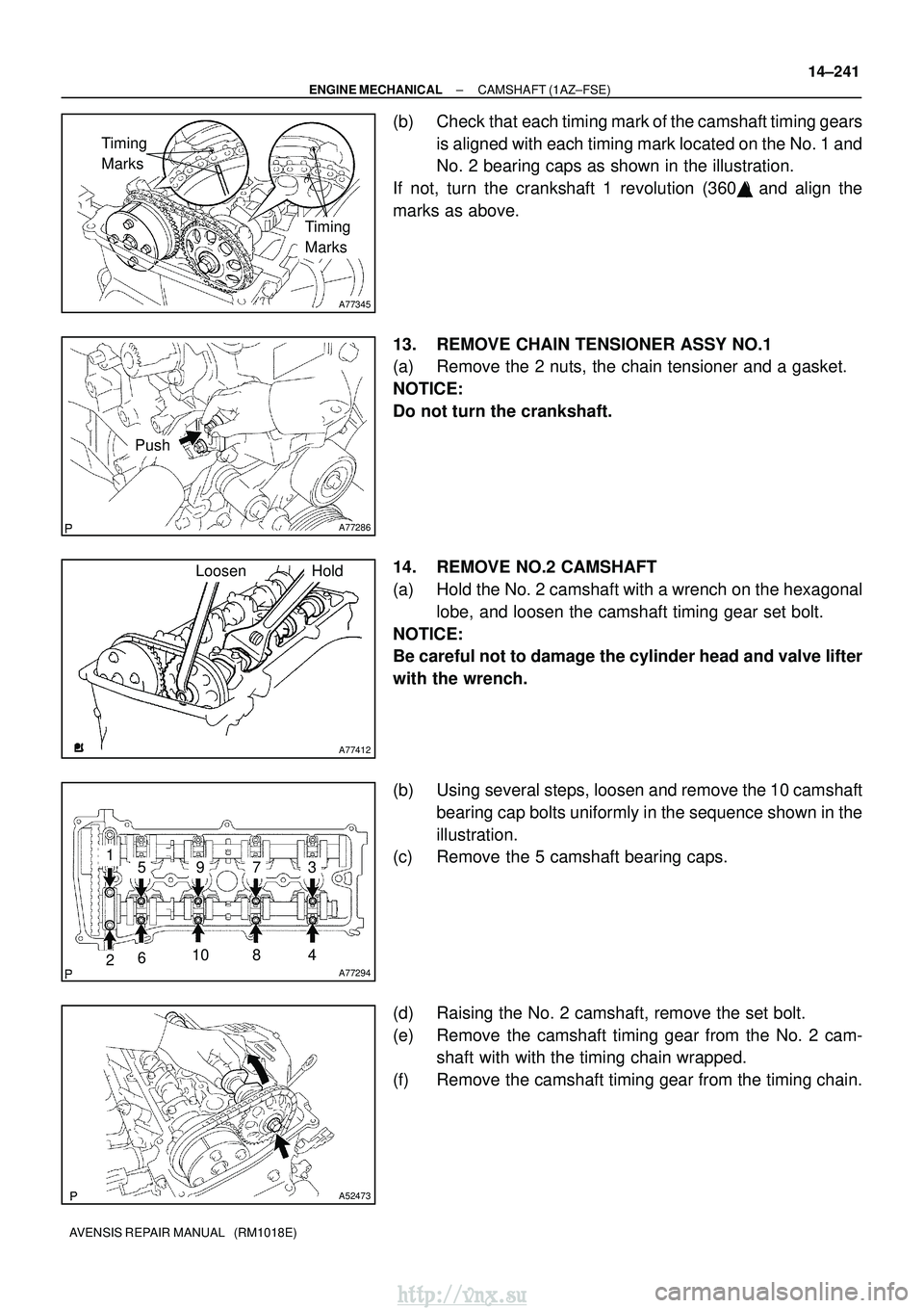
(b) Check that each timing mark of the camshaft timing gears
is aligned with each timing mark located on the No. 1 and
No. 2 bearing caps as shown in the illustration.
If not, turn the crankshaft 1 revolution (360 �) and align the
marks as above.
13. REMOVE CHAIN TENSIONER ASSY NO.1
(a) Remove the 2 nuts, the chain tensioner and a gasket.
NOTICE:
Do not turn the crankshaft.
14. REMOVE NO.2 CAMSHAFT
(a) Hold the No. 2 camshaft with a wrench on the hexagonal lobe, and loosen the camshaft timing gear set bolt.
NOTICE:
Be careful not to damage the cylinder head and valve lifter
with the wrench.
(b) Using several steps, loosen and remove the 10 camshaft bearing cap bolts uniformly in the sequence shown in the
illustration.
(c) Remove the 5 camshaft bearing caps.
(d) Raising the No. 2 camshaft, remove the set bolt.
(e) Remove the camshaft timing gear from the No. 2 cam- shaft with with the timing chain wrapped.
(f) Remove the camshaft timing gear from the timing chain.
http://vnx.su
Page 463 of 2234
A32639
A77414
Straight
Pin
Key
Groove
A77284
A77415Bearing Cap No. 1 Bearing Cap No. 3
5
312 4
±
ENGINE MECHANICAL CAMSHAFT (1AZ±FSE)
14±243
AVENSIS REPAIR MANUAL (RM1018E)
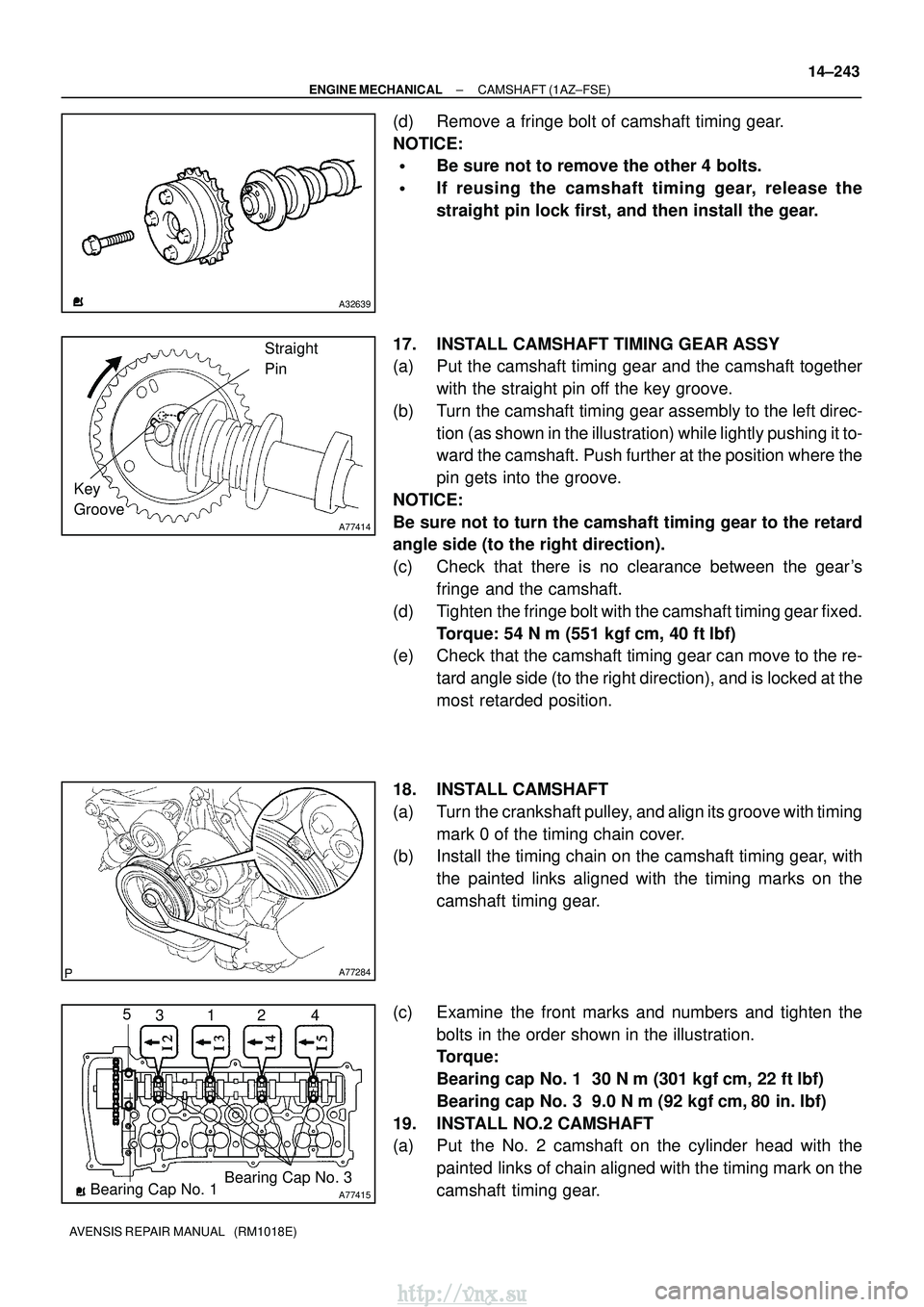
(d) Remove a fringe bolt of camshaft timing gear.
NOTICE:
�Be sure not to remove the other 4 bolts.
�If reusing the camshaft timing gear, release the
straight pin lock first, and then install the gear.
17. INSTALL CAMSHAFT TIMING GEAR ASSY
(a) Put the camshaft timing gear and the camshaft together with the straight pin off the key groove.
(b) Turn the camshaft timing gear assembly to the left direc- tion (as shown in the illustration) while lightly pushing it to-
ward the camshaft. Push further at the position where the
pin gets into the groove.
NOTICE:
Be sure not to turn the camshaft timing gear to the retard
angle side (to the right direction).
(c) Check that there is no clearance between the gear's fringe and the camshaft.
(d) Tighten the fringe bolt with the camshaft timing gear fixed. Torque: 54 N� m (551 kgf�cm, 40 ft�lbf)
(e) Check that the camshaft timing gear can move to the re-
tard angle side (to the right direction), and is locked at the
most retarded position.
18. INSTALL CAMSHAFT
(a) Turn the crankshaft pulley, and align its groove with timing mark 0 of the timing chain cover.
(b) Install the timing chain on the camshaft timing gear, with
the painted links aligned with the timing marks on the
camshaft timing gear.
(c) Examine the front marks and numbers and tighten the bolts in the order shown in the illustration.
Torque:
Bearing cap No. 1 30 N �m (301 kgf� cm, 22 ft�lbf)
Bearing cap No. 3 9.0 N �m (92 kgf �cm, 80 in. �lbf)
19. INSTALL NO.2 CAMSHAFT
(a) Put the No. 2 camshaft on the cylinder head with the painted links of chain aligned with the timing mark on the
camshaft timing gear.
http://vnx.su
Page 464 of 2234
A52473
A77416
Bearing Cap No. 2 Bearing Cap No. 3
531 2 4
A77417
TightenHold
A77345
Timing
Marks
Timing
Marks
A77394
Raise
Pin Hook
Push
14±244
±
ENGINE MECHANICAL CAMSHAFT (1AZ±FSE)
AVENSIS REPAIR MANUAL (RM1018E)
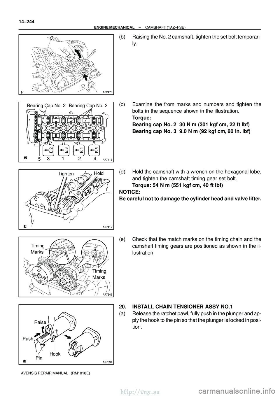
(b) Raising the No. 2 camshaft, tighten the set bolt temporari- ly.
(c) Examine the from marks and numbers and tighten the bolts in the sequence shown in the illustration.
Torque:
Bearing cap No. 2 30 N �m (301 kgf� cm, 22 ft�lbf)
Bearing cap No. 3 9.0 N �m (92 kgf �cm, 80 in. �lbf)
(d) Hold the camshaft with a wrench on the hexagonal lobe, and tighten the camshaft timing gear set bolt.
Torque: 54 N �m (551 kgf� cm, 40 ft�lbf)
NOTICE:
Be careful not to damage the cylinder head and valve lifter.
(e) Check that the match marks on the timing chain and the camshaft timing gears are positioned as shown in the il-
lustration
20. INSTALL CHAIN TENSIONER ASSY NO.1
(a) Release the ratchet pawl, fully push in the plunger and ap- ply the hook to the pin so that the plunger is locked in posi-
tion.
http://vnx.su
Page 465 of 2234
A77395
Engine
Front
A77396
HookPinTurn
Disconnect
A77397
Push Turn
Plunger
±
ENGINE MECHANICALCAMSHAFT(1AZ±FSE)
14±245
AVENSIS REPAIR MANUAL (RM1018E)
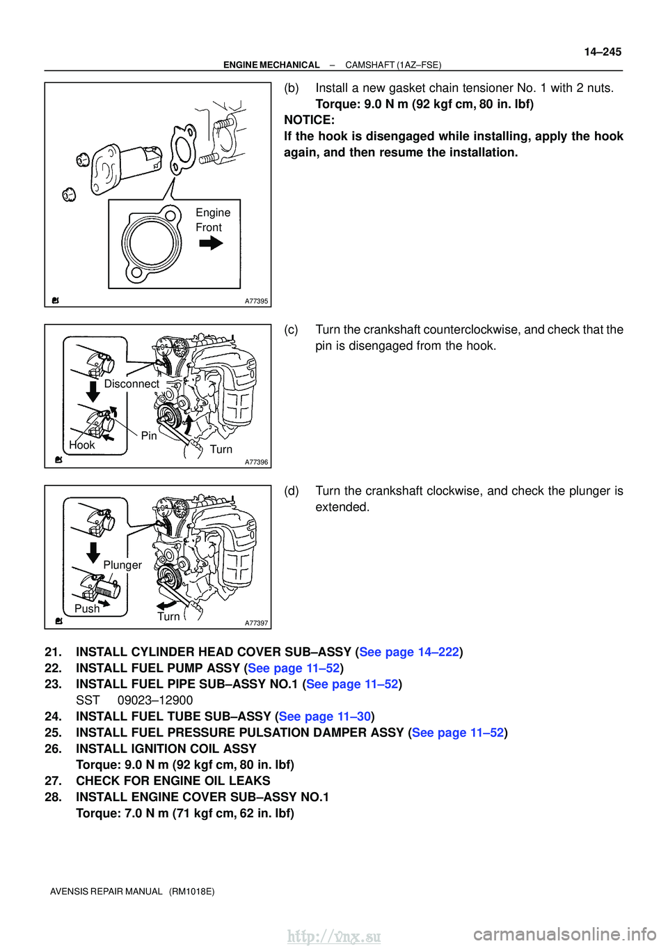
(b)Install a new gasket chain tensioner No. 1 with 2 nuts.
Torque: 9.0 N �m (92 kgf�cm,80 in. �lbf)
NOTICE:
If the hook is disengaged while installing, apply the hook
again, and then resume the installation.
(c)Turn the crankshaft counterclockwise, and check that the
pin is disengaged from the hook.
(d)Turn the crankshaft clockwise, and check the plunger is extended.
21.INSTALL CYLINDER HEAD COVER SUB±ASSY (See page 14±222)
22.INSTALL FUEL PUMP ASSY (See page 11±52)
23.INSTALL FUEL PIPE SUB±ASSY NO.1 (See page 11±52) SST 09023±12900
24.INSTALL FUEL TUBE SUB±ASSY (See page 11±30)
25.INSTALL FUEL PRESSURE PULSATION DAMPER ASSY (See page 11±52)
26. INSTALL IGNITION COIL ASSY Torque: 9.0 N �m (92 kgf �cm, 80 in. �lbf)
27. CHECK FOR ENGINE OIL LEAKS
28. INSTALL ENGINE COVER SUB±ASSY NO.1 Torque: 7.0 N �m (71 kgf �cm, 62 in. �lbf)
http://vnx.su
Page 476 of 2234
A79147
Fulcrum
Length
30 cm
SST
14±324
±
ENGINE MECHANICALCAMSHAFT(1CD±FTV)
AVENSIS REPAIR MANUAL (RM1018E)
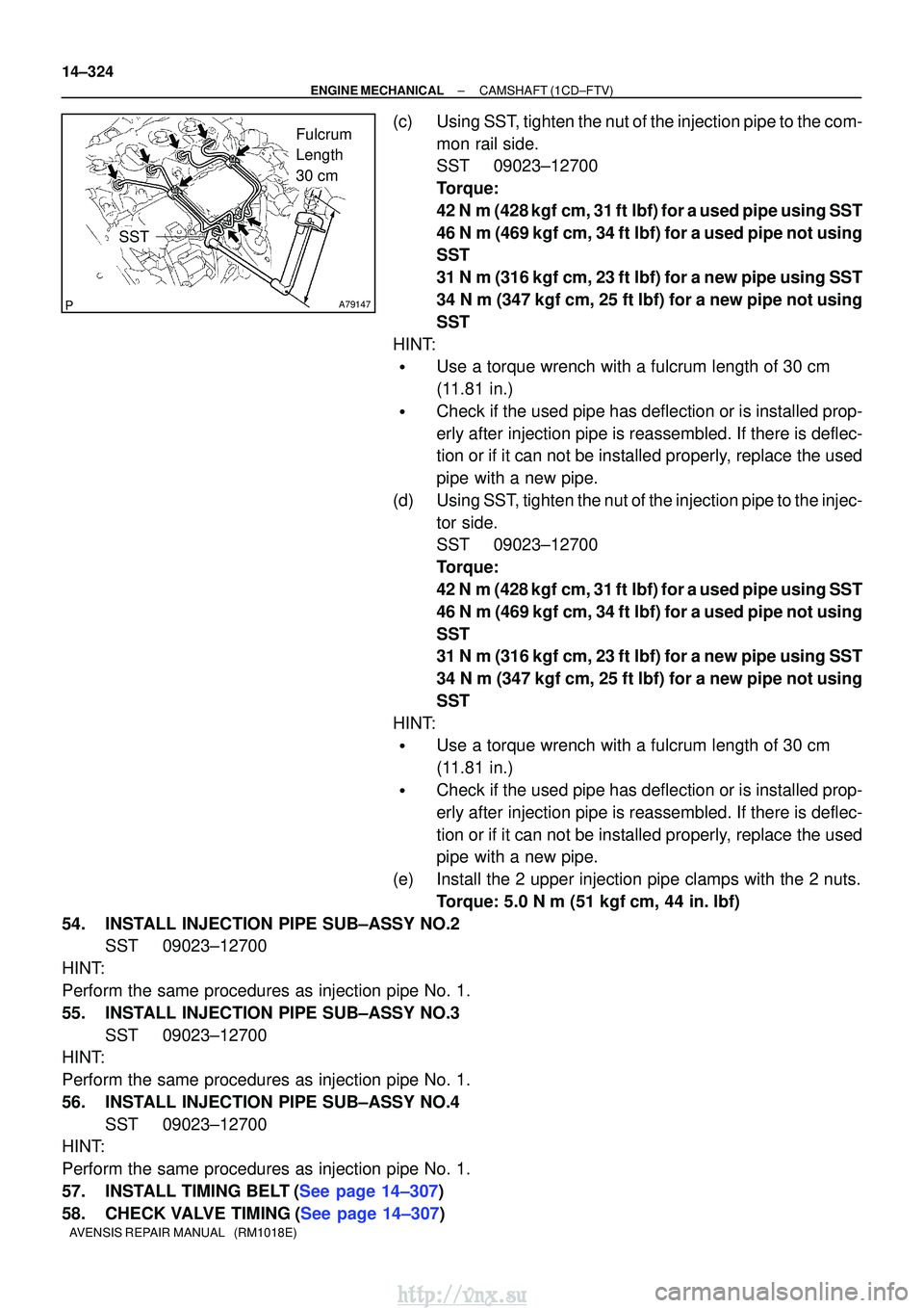
(c)Using SST, tighten the nut of the injection pipe to the com- mon rail side.
SST09023±12700
Torque:
42 N�m (428 kgf�cm, 31 ft�lbf) for a used pipe using SST
46 N�m (469 kgf�cm, 34 ft�lbf) for a used pipe not using
SST
31 N �m (316 kgf�cm, 23 ft�lbf) for a new pipe using SST
34 N�m (347 kgf �cm, 25 ft�lbf) for a new pipe not using
SST
HINT:
�Use a torque wrench with a fulcrum length of 30 cm
(11.81 in.)
�Check if the used pipe has deflection or is installed prop-
erly after injection pipe is reassembled. If there is deflec-
tion or if it can not be installed properly, replace the used
pipe with a new pipe.
(d)Using SST, tighten the nut of the injection pipe to the injec- tor side.
SST09023±12700
Torque:
42 N�m (428 kgf�cm, 31 ft�lbf) for a used pipe using SST
46 N�m (469 kgf�cm, 34 ft�lbf) for a used pipe not using
SST
31 N �m (316 kgf�cm, 23 ft�lbf) for a new pipe using SST
34 N�m (347 kgf �cm, 25 ft�lbf) for a new pipe not using
SST
HINT:
�Use a torque wrench with a fulcrum length of 30 cm
(11.81 in.)
�Check if the used pipe has deflection or is installed prop-
erly after injection pipe is reassembled. If there is deflec-
tion or if it can not be installed properly, replace the used
pipe with a new pipe.
(e)Install the 2 upper injection pipe clamps with the 2 nuts. Torque: 5.0 N �m (51 kgf�cm, 44 in. �lbf)
54.INSTALL INJECTION PIPE SUB±ASSY NO.2 SST09023±12700
HINT:
Perform the same procedures as injection pipe No. 1.
55.INSTALL INJECTION PIPE SUB±ASSY NO.3 SST09023±12700
HINT:
Perform the same procedures as injection pipe No. 1.
56.INSTALL INJECTION PIPE SUB±ASSY NO.4
SST09023±12700
HINT:
Perform the same procedures as injection pipe No. 1.
57.INSTALL TIMING BELT(See page 14±307)
58.CHECK VALVE TIMING(See page 14±307)
http://vnx.su
Page 477 of 2234
±
ENGINE MECHANICAL CAMSHAFT (1CD±FTV)
14±325
AVENSIS REPAIR MANUAL (RM1018E)
59.INSTALL TIMING CHAIN COVER PLATE(See page 14±307)
60.INSTALL TRANSVERSE ENGINE ENGINE MOUNTING BRACKET(See page 14±307)
61.INSTALL TIMING BELT GUIDE(See page 14±307)
62.INSTALL TIMING BELT NO.1 COVER(See page 14±307)
63.INSTALL TIMING BELT NO.2 COVER(See page 14±307)
64.INSTALL IDLER PULLEY SUB±ASSY(See page 14±307)
65.INSTALL CRANKSHAFT PULLEY(See page 14±307)
SST 09213±54015 (90105±08076), 09330±00021
66.INSTALL ENGINE MOUNTING INSULATOR SUB±ASSY RH(See page 14±307)
67.INSTALL POWER STEERING IDLE PULLEY BRACKET (See page 14±286)
68. ADJUST V (COOLER COMPRESSOR TO CRANKSHAFT PULLEY) BELT NO.1 (See page 14±269)
69.INSTALL INJECTOR DRIVER (See page 14±286)
70.INSTALL AIR TUBE NO.1 (See page 14±270)
71. INSTALL VACUUM RESERVOIR SUB±ASSY Torque: 8.3 N �m (85 kgf �cm, 73 in. �lbf)
72.INSTALL AIR CLEANER ASSY (See page 14±286)
73. INSTALL ENGINE COVER NO.1 Torque: 8.0 N �m (82 kgf �cm, 71 in. �lbf)
74. INSTALL FRONT WHEEL RH
Torque: 103 N� m (1,050 kgf�cm, 76 ft �lbf)
75.CHECK FOR FUEL LEAKS(See page 11±60)
http://vnx.su
Page 484 of 2234
A62185
MarkMark
Mark Timing Chain
Cover Surface
Timing
Notch
A11858
A62186
Paint Mark
A62178
Push
14±66
±
ENGINE MECHANICAL CAMSHAFT (1ZZ±FE/3ZZ±FE)
AVENSIS REPAIR MANUAL (RM1018E)
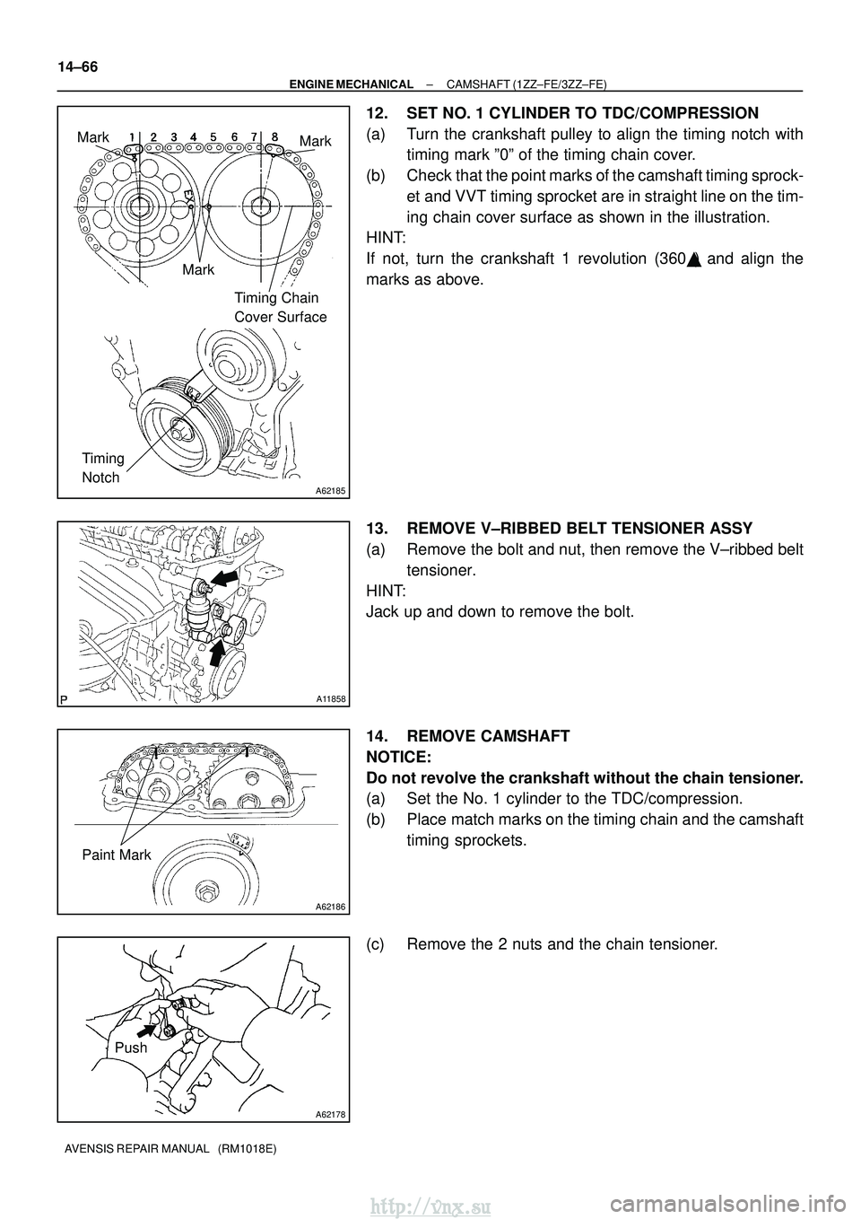
12. SET NO. 1 CYLINDER TO TDC/COMPRESSION
(a) Turn the crankshaft pulley to align the timing notch with timing mark º0º of the timing chain cover.
(b) Check that the point marks of the camshaft timing sprock- et and VVT timing sprocket are in straight line on the tim-
ing chain cover surface as shown in the illustration.
HINT:
If not, turn the crankshaft 1 revolution (360 �) and align the
marks as above.
13. REMOVE V±RIBBED BELT TENSIONER ASSY
(a) Remove the bolt and nut, then remove the V±ribbed belt tensioner.
HINT:
Jack up and down to remove the bolt.
14. REMOVE CAMSHAFT
NOTICE:
Do not revolve the crankshaft without the chain tensioner.
(a) Set the No. 1 cylinder to the TDC/compression.
(b) Place match marks on the timing chain and the camshaft timing sprockets.
(c) Remove the 2 nuts and the chain tensioner.
http://vnx.su
Page 486 of 2234
A32556
A62190
Advance
Side Path
Retard Side
Path
Open
Close
Rubber
Vinyl Tape
Open Close
A62191
Advanced
Side Path
Retard
Side Path
14±68
±
ENGINE MECHANICAL CAMSHAFT (1ZZ±FE/3ZZ±FE)
AVENSIS REPAIR MANUAL (RM1018E)
(i) Tie the timing chain with a string as shown in the illustra- tion.
NOTICE:
Be careful not to drop anything inside the timing chain cov-
er.
15. INSPECT CAMSHAFT TIMING GEAR ASSY
(a) Check the lock of camshaft timing gear.
(1) Clamp the camshaft in a vice, and confirm the cam-shaft timing gear is locked.
NOTICE:
Be careful not to damage the camshaft.
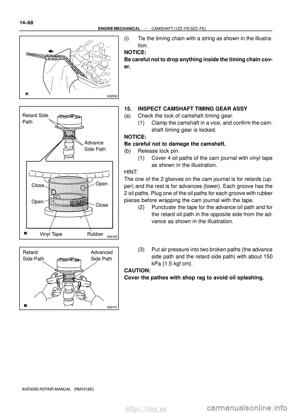
(b) Release lock pin. (1) Cover 4 oil paths of the cam journal with vinyl tapeas shown in the illustration.
HINT:
The one of the 2 glooves on the cam journal is for retards (up-
per) and the rest is for advances (lower). Each groove has the
2 oil paths. Plug one of the oil paths for each groove with rubber
pieces before wrapping the cam journal with the tape. (2) Punctuate the tape for the advance oil path and for
the retard oil path in the opposite side from the ad-
vance as shown in the illustration.
(3) Put air pressure into two broken paths (the advance side path and the retard side path) with about 150
kPa {1.5 kgf� cm}.
CAUTION:
Cover the pathes with shop rag to avoid oil splashing.
http://vnx.su