Page 429 of 2234
1302G±03
A77131
Vacuum Gage
35.7� 3700
100
Throttle Valve Open Position
���
Engine Speed [r/min.]
ON
OFF
A59594
SCV VSV
±
INTAKE INTAKE AIR CONTROL SYSTEM (1AZ±FSE)
13±1
AVENSIS REPAIR MANUAL (RM1018E)
INTAKE AIR CONTROL SYSTEM (1AZ±FSE)
ON±VEHICLE INSPECTION
1. INSPECT INTAKE AIR CONTROL SYSTEM
(a) Using a 3±way connector, connect vacuum gauge to the
actuator hose.
(b) Connect the hand±held tester to the DLC 3.
(c) Start the engine.
(d) Select the active test mode according to the message on the hand±held tester.
Vacuum:
VSV ONApprox. 27 kPa (200 mm Hg, 7.9 in. Hg)
VSV OFF0 kPa (0 mm Hg, 0 in. Hg.)
(e) Shift the transmission into the P range and control the ac-
celerator pedal.
(f) Check the VSV operation using the hang±held tester.
HINT:
The value in the illustration is only for reference; the throttle
valve may operate diversely depend on the engine running
condition.
http://vnx.su
Page 433 of 2234
1302Z±03
A77123
SST
A60595E2 VC
±
INTAKE TURBO CHARGER SYSTEM (1CD±FTV)
13±5
AVENSIS REPAIR MANUAL (RM1018E)
ON±VEHICLE INSPECTION
1. INSPECT INTAKE AIR SYSTEM
(a) Check for leakage or clogging between the air cleaner
housing and turbocharger inlet and between the turbo-
charger outlet and cylinder head.
(1) Clogged air cleaner...Clean or replace element
(2) Hoses collapsed or deformed...Repair or replace
(3) Leakage from connections...Check each connec-tion and repair
(4) Cracks in components...Check and replace
2. INSPECT EXHAUST SYSTEM
(a) Check for leakage or clogging between the cylinder head
and turbocharger inlet and between the turbocharger out-
let and exhaust pipe.
(1) Deformed components...Repair or replace
(2) Foreign material in passages...Remove
(3) Leakage from components...Repair or replace
(4) Cracks in components...Check and replace
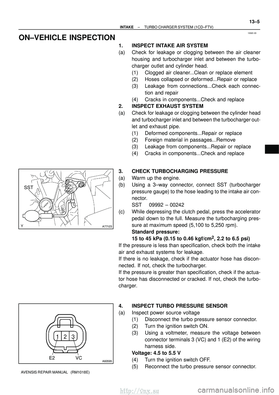
3. CHECK TURBOCHARGING PRESSURE
(a) Warm up the engine.
(b) Using a 3±way connector, connect SST (turbocharger pressure gauge) to the hose leading to the intake air con-
nector.
SST 09992 ± 00242
(c) While depressing the clutch pedal, press the accelerator pedal down to the full. Measure the turbocharging pres-
sure at maximum speed (5,100 to 5,250 rpm).
Standard pressure:
15 to 45 kPa (0.15 to 0.46 kgf/cm
2, 2.2 to 6.5 psi)
If the pressure is less than specification, check both the intake
air and exhaust systems for leakage.
If there is no leakage, check if the actuator hose has discon-
nected. If not, check the turbocharger.
If the pressure is greater than specification, check if the actua-
tor hose has disconnected or cracked. If not, check the turbo-
charger.
4. INSPECT TURBO PRESSURE SENSOR
(a) Inspect power source voltage (1) Disconnect the turbo pressure sensor connector.
(2) Turn the ignition switch ON.
(3) Using a voltmeter, measure the voltage between
connector terminals 3 (VC) and 1 (E2) of the wiring
harness side.
Voltage: 4.5 to 5.5 V
(4) Turn the ignition switch OFF.
(5) Reconnect the turbo pressure sensor connector.
http://vnx.su
Page 435 of 2234
1302Y±03
A77119
A77120
A77121
±
INTAKE TURBO CHARGER SYSTEM (1CD±FTV)
13±3
AVENSIS REPAIR MANUAL (RM1018E)
TURBO CHARGER SYSTEM (1CD±FTV)
PRECAUTION
1. MAINTENANCE PRECAUTION
(a) Do not stop the engine immediately after pulling a trailer,
or after driving at a high speed, or uphill drive. Let the en-
gine Idle for 20 to 120 seconds before turn the ignition
switch OFF (According as the driving condition, the idling
time varies).
(b) Avoid quick acceleration or quickly accelerating the en- gine RPM immediately after the starting a cold engine.
(c) If the turbocharger is found to be defective, it must be re-
placed. Also, inspect a source of the trouble including
conditions of the turbocharger that having been used. Re-
pair or replace the followings as necessary:
(1) Engine oil (Level and quality)
(2) Oil lines leading to the turbocharger
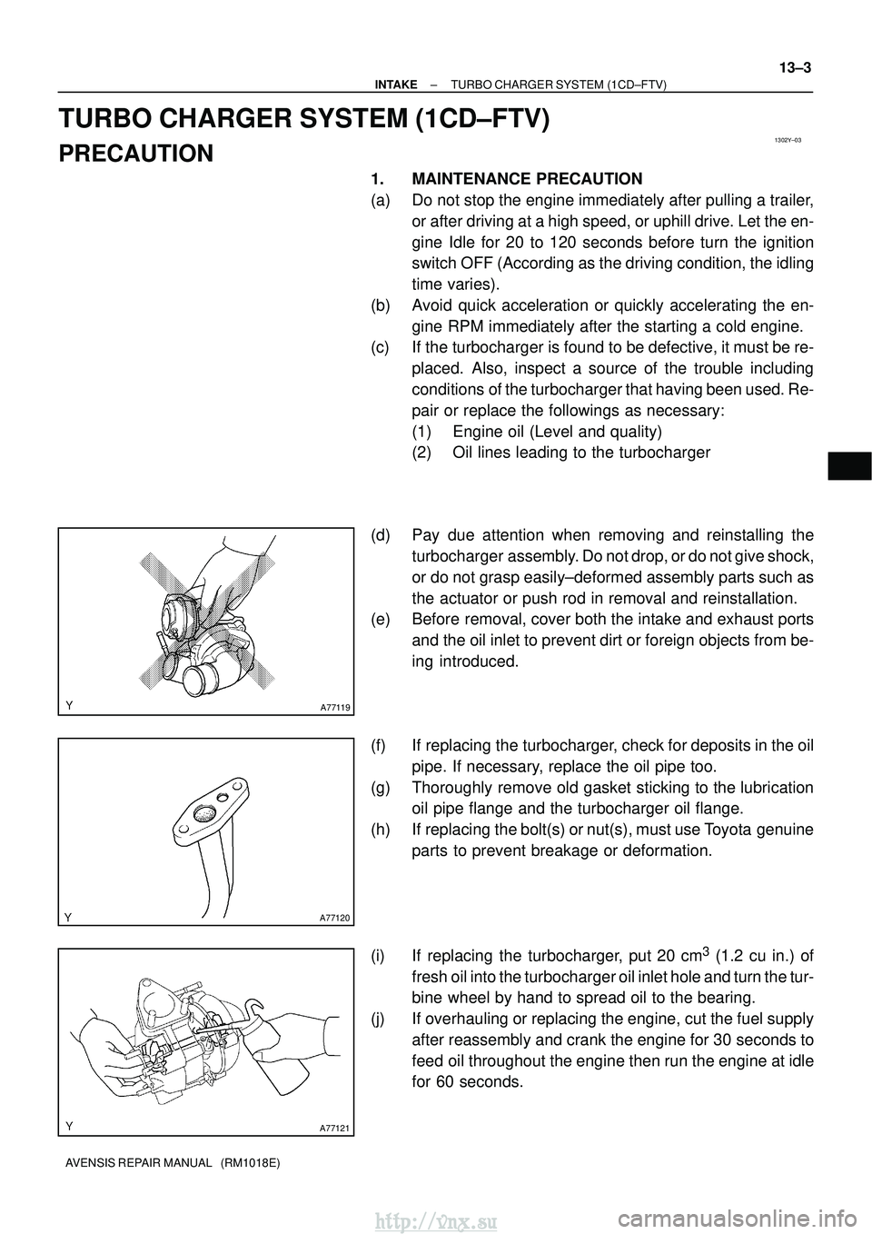
(d) Pay due attention when removing and reinstalling the turbocharger assembly. Do not drop, or do not give shock,
or do not grasp easily±deformed assembly parts such as
the actuator or push rod in removal and reinstallation.
(e) Before removal, cover both the intake and exhaust ports
and the oil inlet to prevent dirt or foreign objects from be-
ing introduced.
(f) If replacing the turbocharger, check for deposits in the oil pipe. If necessary, replace the oil pipe too.
(g) Thoroughly remove old gasket sticking to the lubrication oil pipe flange and the turbocharger oil flange.
(h) If replacing the bolt(s) or nut(s), must use Toyota genuine parts to prevent breakage or deformation.
(i) If replacing the turbocharger, put 20 cm
3 (1.2 cu in.) of
fresh oil into the turbocharger oil inlet hole and turn the tur-
bine wheel by hand to spread oil to the bearing.
(j) If overhauling or replacing the engine, cut the fuel supply after reassembly and crank the engine for 30 seconds to
feed oil throughout the engine then run the engine at idle
for 60 seconds.
http://vnx.su
Page 446 of 2234
A64328
2 to 7 mm0 to 2 mm
A78274
Upward90�
Clamp
Bolt
±
INTAKETURBOCHARGER SUB±ASSY(1CD±FTV)
13±17
AVENSIS REPAIR MANUAL (RM1018E)
41.INSTALL INTERCOOLER AIR HOSE
(a)Install the air hose and hose clamps as shown in the il-
lustration.
(b)Tighten the hose clamps as shown in the illustration. Torque: 6.0 N �m (61 kgf�cm, 53 in. �lbf)
(c)Install the air tube No. 1 with the 3 bolts and nut. Torque: 25 N �m (255 kgf�cm, 18 ft�lbf)
42.INSTALL AIR CLEANER ASSY Torque: 7.0 N �m (71 kgf�cm, 62 in. �lbf)
43.INSTALL VACUUM RESERVOIR SUB±ASSY Torque: 8.3 N �m (85 kgf�cm, 73 in. �lbf)
44.INSTALL ENGINE COVER NO.1
Torque: 8.0 N �m (82 kgf�cm, 71 in. �lbf)
45.ADD ENGINE COOLANT(See page 16±44)
46. CHECK ENGINE OIL LEVEL
47.CHECK FOR ENGINE COOLANT LEAKS(See page 16±44)
48. CHECK FOR ENGINE OIL LEAKS
49.CHECK FOR FUEL LEAKS(See page 11±60)
50. CHECK FOR EXHAUST GAS LEAKS
http://vnx.su
Page 451 of 2234
A77285
Unleaded Gasoline
Leaded GasolineTiming
Marks
Timing
Marks
Timing
Marks
Timing
Marks
A77286
Push
A77412
HoldLoosen
A77294
15973
481062
14±172
±
ENGINE MECHANICAL CAMSHAFT (1AZ±FE)
AVENSIS REPAIR MANUAL (RM1018E)
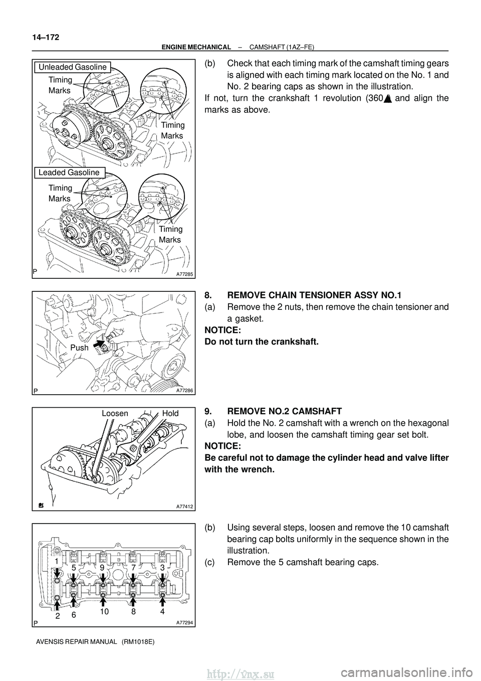
(b) Check that each timing mark of the camshaft timing gears is aligned with each timing mark located on the No. 1 and
No. 2 bearing caps as shown in the illustration.
If not, turn the crankshaft 1 revolution (360 �) and align the
marks as above.
8. REMOVE CHAIN TENSIONER ASSY NO.1
(a) Remove the 2 nuts, then remove the chain tensioner and a gasket.
NOTICE:
Do not turn the crankshaft.
9. REMOVE NO.2 CAMSHAFT
(a) Hold the No. 2 camshaft with a wrench on the hexagonal lobe, and loosen the camshaft timing gear set bolt.
NOTICE:
Be careful not to damage the cylinder head and valve lifter
with the wrench.
(b) Using several steps, loosen and remove the 10 camshaft
bearing cap bolts uniformly in the sequence shown in the
illustration.
(c) Remove the 5 camshaft bearing caps.
http://vnx.su
Page 453 of 2234
A31032
A32639
A77414
Straight
Pin
Key
Groove
14±174
±
ENGINE MECHANICAL CAMSHAFT (1AZ±FE)
AVENSIS REPAIR MANUAL (RM1018E)
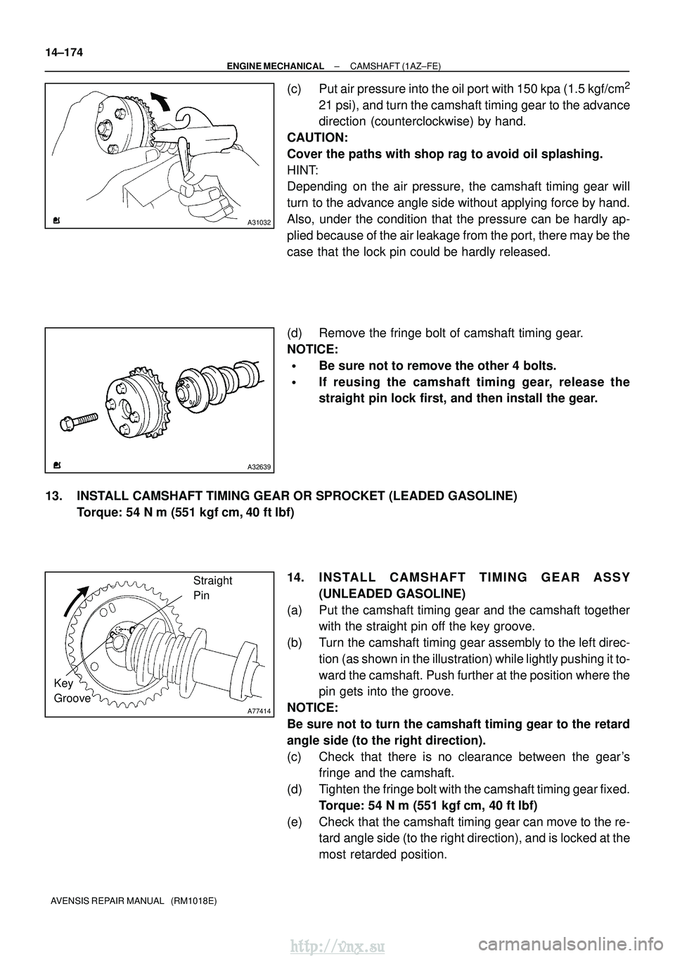
(c) Put air pressure into the oil port with 150 kpa (1.5 kgf/cm2
21 psi), and turn the camshaft timing gear to the advance
direction (counterclockwise) by hand.
CAUTION:
Cover the paths with shop rag to avoid oil splashing.
HINT:
Depending on the air pressure, the camshaft timing gear will
turn to the advance angle side without applying force by hand.
Also, under the condition that the pressure can be hardly ap-
plied because of the air leakage from the port, there may be the
case that the lock pin could be hardly released.
(d) Remove the fringe bolt of camshaft timing gear.
NOTICE:
�Be sure not to remove the other 4 bolts.
�If reusing the camshaft timing gear, release the
straight pin lock first, and then install the gear.
13. INSTALL CAMSHAFT TIMING GEAR OR SPROCKET (LEADED GASOLINE) Torque: 54 N �m (551 kgf� cm, 40 ft�lbf)
14. INSTALL CAMSHAFT TIMING GEAR ASSY (UNLEADED GASOLINE)
(a) Put the camshaft timing gear and the camshaft together with the straight pin off the key groove.
(b) Turn the camshaft timing gear assembly to the left direc- tion (as shown in the illustration) while lightly pushing it to-
ward the camshaft. Push further at the position where the
pin gets into the groove.
NOTICE:
Be sure not to turn the camshaft timing gear to the retard
angle side (to the right direction).
(c) Check that there is no clearance between the gear's fringe and the camshaft.
(d) Tighten the fringe bolt with the camshaft timing gear fixed. Torque: 54 N� m (551 kgf�cm, 40 ft�lbf)
(e) Check that the camshaft timing gear can move to the re- tard angle side (to the right direction), and is locked at the
most retarded position.
http://vnx.su
Page 455 of 2234
A77285
Unleaded Gasoline
Leaded GasolineTiming
Marks
Timing
Marks
Timing
Marks
Timing
Marks
A77394
Raise
Pin Hook
Push
A77395
Engine
Front
14±176
±
ENGINE MECHANICAL CAMSHAFT (1AZ±FE)
AVENSIS REPAIR MANUAL (RM1018E)
(e) Check that the match marks on the timing chain and the camshaft timing gears are positioned as shown in the il-
lustration.
17. INSTALL CHAIN TENSIONER ASSY NO.1
(a) Release the ratchet pawl, fully push in the plunger and ap- ply the hook to the pin so that the plunger is locked in posi-
tion.
(b) Install a new gasket and the chain tensioner No. 1 with the 2 nuts.
Torque: 9.0 N �m (92 kgf �cm, 80 in. �lbf)
NOTICE:
If the hook is disengaged while installing, apply the hook
again, and then resume the installation.
http://vnx.su
Page 456 of 2234
A77396
HookPinTurn
Disconnect
A77397
Push Turn
Plunger
A77399
Seal Packing
A77400NutNut
A
BC
A
AA AB
±
ENGINE MECHANICAL CAMSHAFT (1AZ±FE)
14±177
AVENSIS REPAIR MANUAL (RM1018E)
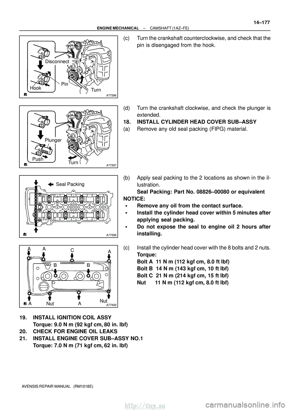
(c) Turn the crankshaft counterclockwise, and check that the
pin is disengaged from the hook.
(d) Turn the crankshaft clockwise, and check the plunger is extended.
18. INSTALL CYLINDER HEAD COVER SUB±ASSY
(a) Remove any old seal packing (FIPG) material.
(b) Apply seal packing to the 2 locations as shown in the il- lustration.
Seal Packing: Part No. 08826±00080 or equivalent
NOTICE:
�Remove any oil from the contact surface.
�Install the cylinder head cover within 5 minutes after
applying seal packing.
�Do not expose the seal to engine oil 2 hours after
installing.
(c) Install the cylinder head cover with the 8 bolts and 2 nuts. Torque:
Bolt A 11 N �m (112 kgf �cm, 8.0 ft� lbf)
Bolt B 14 N �m (143 kgf� cm, 10 ft�lbf)
Bolt C 21 N �m (214 kgf� cm, 15 ft�lbf)
Nut 11 N �m (112 kgf �cm, 8.0 ft� lbf)
19. INSTALL IGNITION COIL ASSY Torque: 9.0 N �m (92 kgf �cm, 80 in. �lbf)
20. CHECK FOR ENGINE OIL LEAKS
21. INSTALL ENGINE COVER SUB±ASSY NO.1
Torque: 7.0 N �m (71 kgf �cm, 62 in. �lbf)
http://vnx.su