Page 972 of 2234

19±29
AVENSIS REPAIR MANUAL (RM1018E)
GENERATOR ASSY(1CD±FTV)
REPLACEMENT
1.REMOVE FRONT WHEEL RH
2.REMOVE RADIATOR SUPPORT OPENING")
190O1±01
A79176
±
STARTING & CHARGINGGENERATOR ASSY(1CD±FTV)
19±29
AVENSIS REPAIR MANUAL (RM1018E)
GENERATOR ASSY(1CD±FTV)
REPLACEMENT
1.REMOVE FRONT WHEEL RH
2.REMOVE RADIATOR SUPPORT OPENING COVER
3.REMOVE ENGINE ROOM COVER SIDE
4.REMOVE ENGINE UNDER COVER SUB±ASSY NO.1
5.REMOVE ENGINE UNDER COVER RH
6.REMOVE V (COOLER COMPRESSOR TO CRANKSHAFT PULLEY) BELT NO.1
(See page 14±269)
7.REMOVE GENERATOR V BELT (See page 14±269)
8.REMOVE FLOOR PANEL BRACE FRONT(See page 15±10)
9.REMOVE EXHAUST PIPE ASSY FRONT(See page 15±10)
10.REMOVE EXHAUST PIPE ASSY (W/ COLD AREA) (See page 13±11)
11.REMOVE GENERATOR ASSY
(a)Remove the bolt and disconnect the wire harness.
(b)Remove the cap and nut, disconnect the generator wire.
(c)Disconnect the generator connector.
(d)Remove the 2 bolts and the generator.
12.INSTALL GENERATOR ASSY Torque:
31 N�m (320 kgf�cm, 23 ft�lbf) for M8
47 N�m (475 kgf�cm, 34 ft�lbf) for M10
9.8 N�m (100 kgf�cm, 7 ft �lbf) for Generator wire
5.0 N�m (51 kgf �cm, 44 ft�lbf) for Wire harness
13.INSTALL EXHAUST PIPE ASSY (W/ COLD AREA) (See page 13±11)
14.INSTALL EXHAUST PIPE ASSY FRONT(See page 15±10)
15.INSTALL FLOOR PANEL BRACE FRONT(See page 15±10)
16. ADJUST V (COOLER COMPRESSOR TO CRANKSHAFT PULLEY) BELT NO.1 (See page 14±286)
17. INSTALL FRONT WHEEL RH Torque: 103 N� m (1,050 kgf�cm, 76 ft �lbf)
18. CHECK FOR EXHAUST GAS LEAKS
http://vnx.su
Page 990 of 2234
2600M±04
F13686
C80880
F13683
F44622
26±10
±
FRONT SUSPENSION FRONT SHOCK ABSORBER WITH COIL SPRING
AVENSIS REPAIR MANUAL (RM1018E)
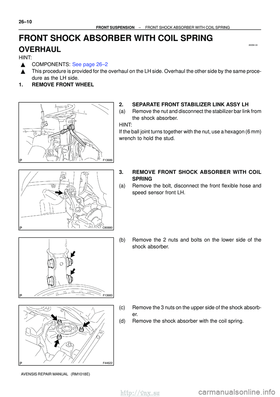
FRONT SHOCK ABSORBER WITH COIL SPRING
OVERHAUL
HINT:
�COMPONENTS: See page 26±2
�This procedure is provided for the overhaul on the LH side. Overhaul the oth\
er side by the same proce-
dure as the LH side.
1. REMOVE FRONT WHEEL
2. SEPARATE FRONT STABILIZER LINK ASSY LH
(a) Remove the nut and disconnect the stabilizer bar link fromthe shock absorber.
HINT:
If the ball joint turns together with the nut, use a hexagon (6 mm)
wrench to hold the stud.
3. REMOVE FRONT SHOCK ABSORBER WITH COIL SPRING
(a) Remove the bolt, disconnect the front flexible hose and speed sensor front LH.
(b) Remove the 2 nuts and bolts on the lower side of the shock absorber.
(c) Remove the 3 nuts on the upper side of the shock absorb- er.
(d) Remove the shock absorber with the coil spring.
http://vnx.su
Page 1003 of 2234
26±19
AVENSIS REPAIR MANUAL (RM1018E)
19. CONNECT FRONT SUSPENSION ARM SUB±ASSY
LOWER NO.1 LH
(a) Connect")
C80293
F13686
C80889
±
FRONT SUSPENSION FRONT SUSPENSION ARM SUB±ASSY LOWER NO.1
LH (ATM)26±19
AVENSIS REPAIR MANUAL (RM1018E)
19. CONNECT FRONT SUSPENSION ARM SUB±ASSY
LOWER NO.1 LH
(a) Connect the lower suspension arm to the lower ball joint
with the 2 nuts and bolt.
Torque: 89 N �m (908 kgf� cm, 66 ft�lbf)
20. CONNECT FRONT SUSPENSION ARM SUB±ASSY LOWER NO.1 RH
HINT:
Connect the RH side by the same procedures as the LH side.
21.INSTALL TIE ROD END SUB±ASSY LH (See page 30±6)
22. INSTALL TIE ROD END SUB±ASSY RH
HINT:
Connect the RH side by the same procedures as the LH side. 23. CONNECT FRONT STABILIZER LINK ASSY LH
(a) Install the stabilizer bar link with the nut.Torque: 74 N �m (755 kgf� cm, 55 ft�lbf)
HINT:
If the ball joint turns together with the nut, use a hexagon (6 mm)
wrench to hold the stud.
24. CONNECT FRONT STABILIZER LINK ASSY RH
HINT:
Install the RH side by the same procedures as the LH side.
25. STABILIZE SUSPENSION
(a) Install the front wheel and jack down the vehicle. Torque: 103 N� m (1,050 kgf�cm, 76 ft �lbf)
(b) Bounce the vehicle up and down several times to stabilize the suspension\
.
26. FULLY TIGHTEN FRONT SUSPENSION ARMSUB±ASSY LOWER NO.1 LH
(a) Fully tighten the 2 bolts and nut.
Torque: 137 N� m (1,400 kgf�cm, 101 ft� lbf)
http://vnx.su
Page 1005 of 2234
26±21
AVENSIS REPAIR MANUAL (RM1018E)
FRONT SUSPENSION ARM SUB±ASSY LOWER NO.1
LH (MTM)
REPLACE")
260DR±01
F13686
F41742
C80889
±
FRONT SUSPENSION FRONT SUSPENSION ARM SUB±ASSY LOWER NO.1
LH (MTM)26±21
AVENSIS REPAIR MANUAL (RM1018E)
FRONT SUSPENSION ARM SUB±ASSY LOWER NO.1
LH (MTM)
REPLACEMENT
HINT:
�COMPONENTS: See page 26±2
�Replace the RH side (Engine: 1AZ) by the same procedures as the LH (A\
TM) side.
�Replace the RH side (Engine: 1ZZ, 3ZZ, 1CD) by the same procedures as \
the LH (MTM) side.
1. REMOVE FRONT WHEELS
2. SEPARATE FRONT STABILIZER LINK ASSY LH
(a) Remove the nut and disconnect the stabilizer bar link fromthe shock absorber.
HINT:
If the ball joint turns together with the nut, use a hexagon (6 mm)
wrench to hold the stud.
3. SEPARATE FRONT STABILIZER LINK ASSY RH
HINT:
Separate the RH side by the same procedures as the LH side. 4. SEPARATE FRONT SUSPENSION ARM SUB±ASSYLOWER NO.1 LH
(a) Remove the bolt and 2 nuts, and separate the lower sus- pension arm from the lower ball joint.
5. REMOVE FRONT SUSPENSION ARM SUB±ASSY LOWER NO.1 LH
(a) Remove the 2 bolts, nut and lower suspension arm sub±
assy lower No.1 LH from the front suspension crossmem-
ber sub±assy.
http://vnx.su
Page 1006 of 2234

AVENSIS REPAIR MANUAL (RM1018E)
6. TEMPORARILY TIGHTEN FRONT SUSPENSION ARM SUB±ASSY LOWER N")
C80889
F41742
F13686
C80889
26±22±
FRONT SUSPENSION FRONT SUSPENSION ARM SUB±ASSY LOWER NO.1
LH (MTM)
AVENSIS REPAIR MANUAL (RM1018E)
6. TEMPORARILY TIGHTEN FRONT SUSPENSION ARM SUB±ASSY LOWER NO.1 LH
(a) Install the lower suspension arm, temporary tighten the 2
bolts and nut.
7. CONNECT FRONT SUSPENSION ARM SUB±ASSY LOWER NO.1 LH
(a) Connect the lower suspension arm to the lower ball joint with the 2 nuts and bolt.
Torque: 89 N �m (908 kgf� cm, 66 ft�lbf)
8. CONNECT FRONT STABILIZER LINK ASSY LH
(a) Install the stabilizer bar link with the nut. Torque: 74 N �m (755 kgf� cm, 55 ft�lbf)
HINT:
If the ball joint turns together with the nut, use a hexagon (6 mm)
wrench to hold the stud.
9. CONNECT FRONT STABILIZER LINK ASSY RH
HINT:
Install the RH side by the same procedures as the LH side.
10. STABILIZE SUSPENSION
(a) Install the front wheel and jack down the vehicle. Torque: 103 N� m (1,050 kgf�cm, 76 ft �lbf)
(b) Bounce the vehicle up and down several times to stabilize the suspension\
.
11. FULLY TIGHTEN FRONT SUSPENSION ARMSUB±ASSY LOWER NO.1 LH
(a) Fully tighten the 2 bolts and nut.
Torque: 137 N� m (1,400 kgf�cm, 101 ft� lbf)
http://vnx.su
Page 1011 of 2234
F13683
26±8
±
FRONT SUSPENSION FRONT WHEEL ALIGNMENT
AVENSIS REPAIR MANUAL (RM1018E)
7. ADJUST CAMBER
NOTICE:
After the camber has been adjusted, inspect the toe±in.
(a) Remove the front wheel.
(b) Remove the 2 bolts and nuts on the lower side of the shock absorber.
If reusing the bolts and/or nuts, coat the threads of nuts with en-
gine oil.
(c) Clean the installation surfaces of the shock absorber and the steering knuckle.
(d) Temporarily install the 2 bolts and nuts.
http://vnx.su
Page 1012 of 2234

F44962
+
±
F13685
1
2
F12938
Bolt
Adjusting
Value Set Bolt
Adjusting Bolt90105±17008 90105±17009
90105±17010 90105±17011
121212121 Dot
2 Dots3 Dots
±1
�30' ± ±1� 15'
±1 �15' ± ±1� 00'
±1 �00' ± ±45'
±45' ± ±30'
±30' ± ±15'
0' ± 15'
15' ± 30'
30' ± 45'
45' ± 1����
1 �00' ± 1� 15'
±15' ± 0'
1 �15' ± 1� 30'
±
FRONT SUSPENSION FRONT WHEEL ALIGNMENT
26±9
AVENSIS REPAIR MANUAL (RM1018E)
(e) Adjust the camber by pushing or pulling the lower side of
the shock absorber in the direction in which the camber
adjustment is required.
(f) Tighten the nuts. Torque: 220 N� m (2,240 kgf�cm, 162 ft� lbf)
(g) Install the front wheel. Torque: 103 N´m (1,050 kgf´cm, 76 ft´lbf)
(h) Check the camber.
HINT:
�Adjust the camber to the center of the specified value as
much as possible.
�Adjusting value for the set bolts is 6' ± 30' (0.1 � ± 0.5 �).
If the camber is not within the specified value, using the follow-
ing table, estimate how much additional camber adjustment will
be required, and select the camber adjusting bolt.
NOTICE:
Tighten the adjusting bolt with a washer and a new nut.
(i) Perform the procedure mentioned above again. At step (b), replace 1 or 2 selected bolts.
HINT:
When replacing the 2 bolts, replace 1 bolt for each time.
http://vnx.su
Page 1017 of 2234

21. INSTALL FRONT STABILIZER BRACKET NO.1 RH
(a) w/ HID: Install the front stabilizer bracket No.1 R")
F45155
A
B
F44620
26±28
±
FRONT SUSPENSION STABILIZER BAR FRONT
AVENSIS REPAIR MANUAL (RM1018E)
21. INSTALL FRONT STABILIZER BRACKET NO.1 RH
(a) w/ HID: Install the front stabilizer bracket No.1 RH and the height
control sensor (Front) with the 3 bolts.
Torque:
Bolt A: 5.4 N� m (55 kgf�cm, 48 in. �lbf)
Bolt B: 19 N� m (194 kgf�cm, 14 ft�lbf)
(b) w/o HID: Install the front stabilizer bracket No.1 RH with the 2 bolts.
Torque: 19 N� m (194 kgf�cm, 14 ft�lbf)
22.INSTALL FRONT SUSPENSION CROSSMEMBER SUB±ASSY (See page 26±16)
23.INSTALL FRONT SUSPENSION MEMBER BRACE REAR LH (See page 26±16)
24. INSTALL FRONT SUSPENSION MEMBER BRACE REAR RH
HINT:
Install the RH side by the same procedures as the LH side.
25. INSTALL RACK & PINION POWER STEERING GEAR ASSY
(a)Electric power steering model: See page 51±28
(b)Oil pressure power steering model: See page 51±36
26.INSTALL FRONT SUSPENSION ARM SUB±ASSY LOWER NO.1 LH (See page 30±6)
27. INSTALL FRONT SUSPENSION ARM SUB±ASSY LOWER NO.1 RH
HINT:
Connect the RH side by the same procedures as the LH side.
28.INSTALL TIE ROD END SUB±ASSY LH (See page 30±6)
29. INSTALL TIE ROD END SUB±ASSY RH
HINT:
Connect the RH side by the same procedures as the LH side.
30. INSTALL FRONT STABILIZER LINK ASSY LH
(a) Install the front stabilizer link assy LH with the 2 nuts.Torque: 74 N �m (755 kgf� cm, 55 ft�lbf)
HINT:
If the ball joint turns together with the nut, use a hexagon
wrench (6 mm) to hold the stud.
31. INSTALL FRONT STABILIZER LINK ASSY RH
HINT:
Install the RH side by the same procedures as the LH side.
32. INSTALL FRONT WHEEL Torque: 103 N� m (1,050 kgf�cm, 76 ft �lbf)
33.INSPECT AND ADJUST FRONT WHEEL ALIGNMENT (See page 26±6)
34.HEADLIGHT AIM ONLY (W/ DISCHARGE HEAD LAMP) (See page 65±19)
http://vnx.su

7. ADJUST CAMBER
NOTICE:
After the camber has been adjusted, inspect the toe±in.
(a) Remove the front wheel.
(")