Page 1074 of 2234
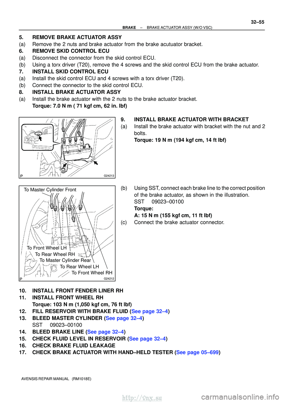
G24213
To Master Cylinder Front
G24212
To Master Cylinder Rear
To Front Wheel RH
To Rear Wheel LH
To Rear Wheel RH
To Front Wheel LH
±
BRAKEBRAKE ACTUATOR ASSY(W/O VSC)
32±55
AVENSIS REPAIR MANUAL (RM1018E)
5.REMOVE BRAKE ACTUATOR ASSY
(a)Remove the 2 nuts and brake actuator from the brake acutuator bracket.
6.REMOVE SKID CONTROL ECU
(a)Disconnect the connector from the skid control ECU.
(b)Using a torx driver (T20), remove the 4 screws and the skid control EC\
U from the brake actuator.
7.INSTALL SKID CONTROL ECU
(a)Install the skid control ECU and 4 screws with a torx driver (T20).
(b)Connect the connector to the skid control ECU.
8.INSTALL BRAKE ACTUATOR ASSY
(a)Install the brake actuator with the 2 nuts to the brake actuator bracket\
.
Torque: 7.0 N �m ( 71 kgf�cm, 62 in. �lbf)
9.INSTALL BRAKE ACTUATOR WITH BRACKET
(a)Install the brake actuator with bracket with the nut and 2 bolts.
Torque: 19 N �m (194 kgf�cm, 14 ft�lbf)
(b)Using SST, connect each brake line to the correct position of the brake actuator, as shown in the illustration.
SST09023±00100
Torque:
A: 15 N�m (155 kgf�cm, 11 ft �lbf)
(c)Connect the brake actuator connector.
10.INSTALL FRONT FENDER LINER RH
11.INSTALL FRONT WHEEL RH Torque: 103 N�m (1,050 kgf�cm, 76 ft�lbf)
12.FILL RESERVOIR WITH BRAKE FLUID (See page 32±4)
13.BLEED MASTER CYLINDER (See page 32±4) SST 09023±00100
14.BLEED BRAKE LINE (See page 32±4)
15.CHECK FLUID LEVEL IN RESERVOIR (See page 32±4)
16. CHECK BRAKE FLUID LEAKAGE
17.CHECK BRAKE ACTUATOR WITH HAND±HELD TESTER (See page 05±699)
http://vnx.su
Page 1084 of 2234
F45057
w/o VSC:
w/ VSC:
To Master
Cylinder Rear
To
Master
Cylinder
Front
To Rear Wheel
RH
To Front Wheel LH
To Front Wheel RH
To Rear Wheel
LH
A
To
Master
Cylinder
FrontTo Master
Cylinder
Rear
To Rear
Wheel RH
To Front Wheel LHTo Front Wheel RH
To Rear
Wheel LH
AA
AA
BB
C80802
C80806
32±26
±
BRAKE BRAKE BOOSTER ASSY (RHD)
AVENSIS REPAIR MANUAL (RM1018E)
(c) Use tags or make a memo to identify the place to recon- nect.
(d) Using SST and a spanner, disconnect the brake tube from the flexible hose of the front brake RH.
SST 09023±00100
(e) Remove the 2 bolts and disconnect the 2 brake tube clamps.
http://vnx.su
Page 1089 of 2234
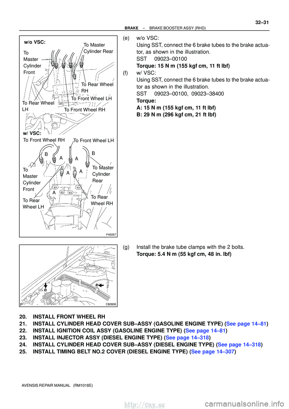
F45057
w/o VSC:
w/ VSC:
To Master
Cylinder Rear
To
Master
Cylinder
Front
To Rear Wheel
RH
To Front Wheel LH
To Front Wheel RH
To Rear Wheel
LH
A
To
Master
Cylinder
FrontTo Master
Cylinder
Rear
To Rear
Wheel RH
To Front Wheel LHTo Front Wheel RH
To Rear
Wheel LH
AA
AA
BB
C80806
±
BRAKE BRAKE BOOSTER ASSY (RHD)
32±31
AVENSIS REPAIR MANUAL (RM1018E)
(e) w/o VSC:
Using SST, connect the 6 brake tubes to the brake actua-
tor, as shown in the illustration.
SST 09023±00100
Torque: 15 N �m (155 kgf� cm, 11 ft�lbf)
(f) w/ VSC: Using SST, connect the 6 brake tubes to the brake actua-
tor as shown in the illustration.
SST 09023±00100, 09023±38400
Torque:
A: 15 N� m (155 kgf� cm, 11 ft�lbf)
B: 29 N� m (296 kgf� cm, 21 ft�lbf)
(g) Install the brake tube clamps with the 2 bolts. Torque: 5.4 N �m (55 kgf �cm, 48 in. �lbf)
20. INSTALL FRONT WHEEL RH
21.INSTALL CYLINDER HEAD COVER SUB±ASSY (GASOLINE ENGINE TYPE) (See page 14±81)
22.INSTALL IGNITION COIL ASSY (GASOLINE ENGINE TYPE) (See page 14±81)
23.INSTALL INJECTOR ASSY (DIESEL ENGINE TYPE) (See page 14±318)
24.INSTALL CYLINDER HEAD COVER SUB±ASSY (DIESEL ENGINE TYPE) (See page 14±318)
25.INSTALL TIMING BELT NO.2 COVER (DIESEL ENGINE TYPE) (See page 14±307)
http://vnx.su
Page 1108 of 2234
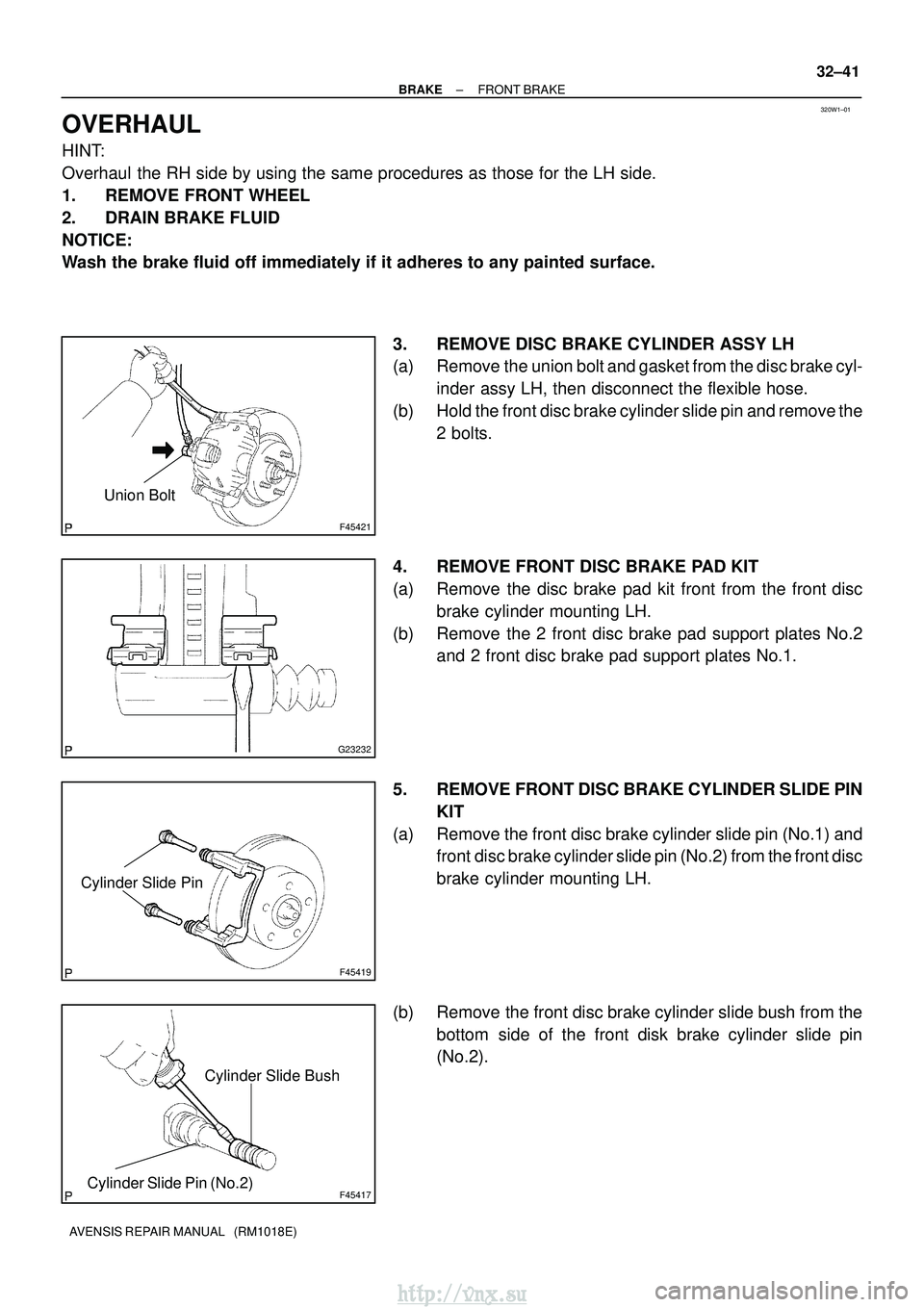
320W1±01
F45421
Union Bolt
G23232
F45419
Cylinder Slide Pin
F45417
Cylinder Slide Bush
Cylinder Slide Pin (No.2)
±
BRAKE FRONT BRAKE
32±41
AVENSIS REPAIR MANUAL (RM1018E)
OVERHAUL
HINT:
Overhaul the RH side by using the same procedures as those for the LH side.
1. REMOVE FRONT WHEEL
2. DRAIN BRAKE FLUID
NOTICE:
Wash the brake fluid off immediately if it adheres to any painted surface\
.
3. REMOVE DISC BRAKE CYLINDER ASSY LH
(a) Remove the union bolt and gasket from the disc brake cyl-inder assy LH, then disconnect the flexible hose.
(b) Hold the front disc brake cylinder slide pin and remove the 2 bolts.
4. REMOVE FRONT DISC BRAKE PAD KIT
(a) Remove the disc brake pad kit front from the front disc brake cylinder mounting LH.
(b) Remove the 2 front disc brake pad support plates No.2 and 2 front disc brake pad support plates No.1.
5. REMOVE FRONT DISC BRAKE CYLINDER SLIDE PIN KIT
(a) Remove the front disc brake cylinder slide pin (No.1) and front disc brake cylinder slide pin (No.2) from the front disc
brake cylinder mounting LH.
(b) Remove the front disc brake cylinder slide bush from the bottom side of the front disk brake cylinder slide pin
(No.2).
http://vnx.su
Page 1112 of 2234
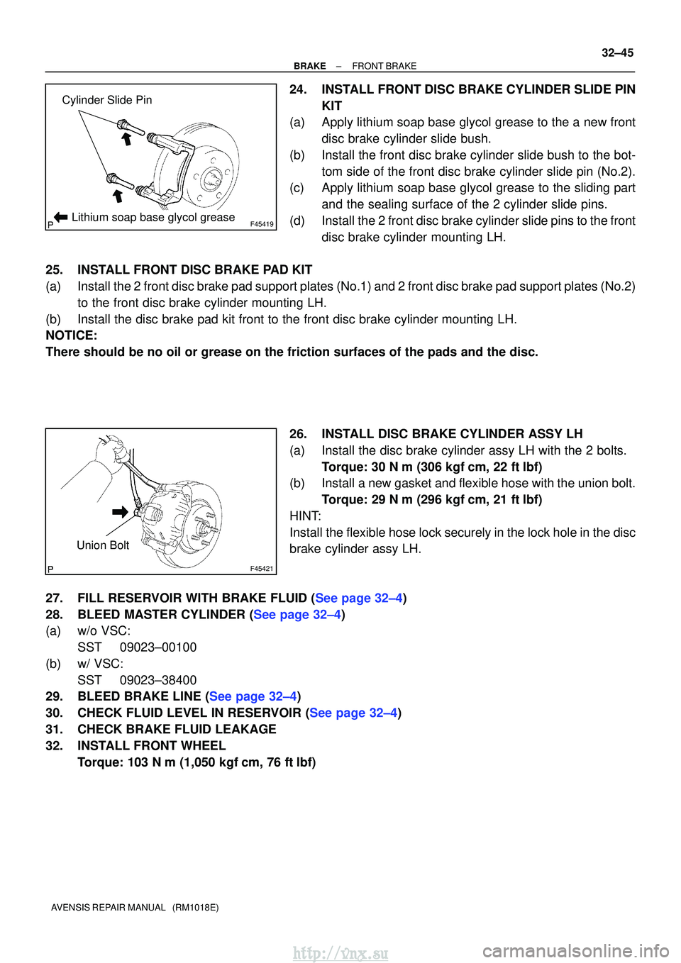
F45419
Cylinder Slide Pin
Lithium soap base glycol grease
F45421
Union Bolt
±
BRAKE FRONT BRAKE
32±45
AVENSIS REPAIR MANUAL (RM1018E)
24. INSTALL FRONT DISC BRAKE CYLINDER SLIDE PIN
KIT
(a) Apply lithium soap base glycol grease to the a new front
disc brake cylinder slide bush.
(b) Install the front disc brake cylinder slide bush to the bot- tom side of the front disc brake cylinder slide pin (No.2).
(c) Apply lithium soap base glycol grease to the sliding part
and the sealing surface of the 2 cylinder slide pins.
(d) Install the 2 front disc brake cylinder slide pins to the front disc brake cylinder mounting LH.
25. INSTALL FRONT DISC BRAKE PAD KIT
(a) Install the 2 front disc brake pad support plates (No.1) and 2 front disc bra\
ke pad support plates (No.2) to the front disc brake cylinder mounting LH.
(b) Install the disc brake pad kit front to the front disc brake cylinder mo\
unting LH.
NOTICE:
There should be no oil or grease on the friction surfaces of the pads an\
d the disc.
26. INSTALL DISC BRAKE CYLINDER ASSY LH
(a) Install the disc brake cylinder assy LH with the 2 bolts.Torque: 30 N �m (306 kgf� cm, 22 ft�lbf)
(b) Install a new gasket and flexible hose with the union bolt.
Torque: 29 N� m (296 kgf�cm, 21 ft�lbf)
HINT:
Install the flexible hose lock securely in the lock hole in the disc
brake cylinder assy LH.
27.FILL RESERVOIR WITH BRAKE FLUID (See page 32±4)
28.BLEED MASTER CYLINDER (See page 32±4)
(a) w/o VSC: SST 09023±00100
(b) w/ VSC: SST 09023±38400
29.BLEED BRAKE LINE (See page 32±4)
30.CHECK FLUID LEVEL IN RESERVOIR (See page 32±4)
31. CHECK BRAKE FLUID LEAKAGE
32. INSTALL FRONT WHEEL
Torque: 103 N� m (1,050 kgf�cm, 76 ft �lbf)
http://vnx.su
Page 1114 of 2234
320W0±01
G23181
Union bolt
G23224
F45701
Cylinder Slide Pin
F45417
Cylinder Slide Bush
Cylinder Slide Pin (No.2)
±
BRAKE REAR BRAKE
32±47
AVENSIS REPAIR MANUAL (RM1018E)
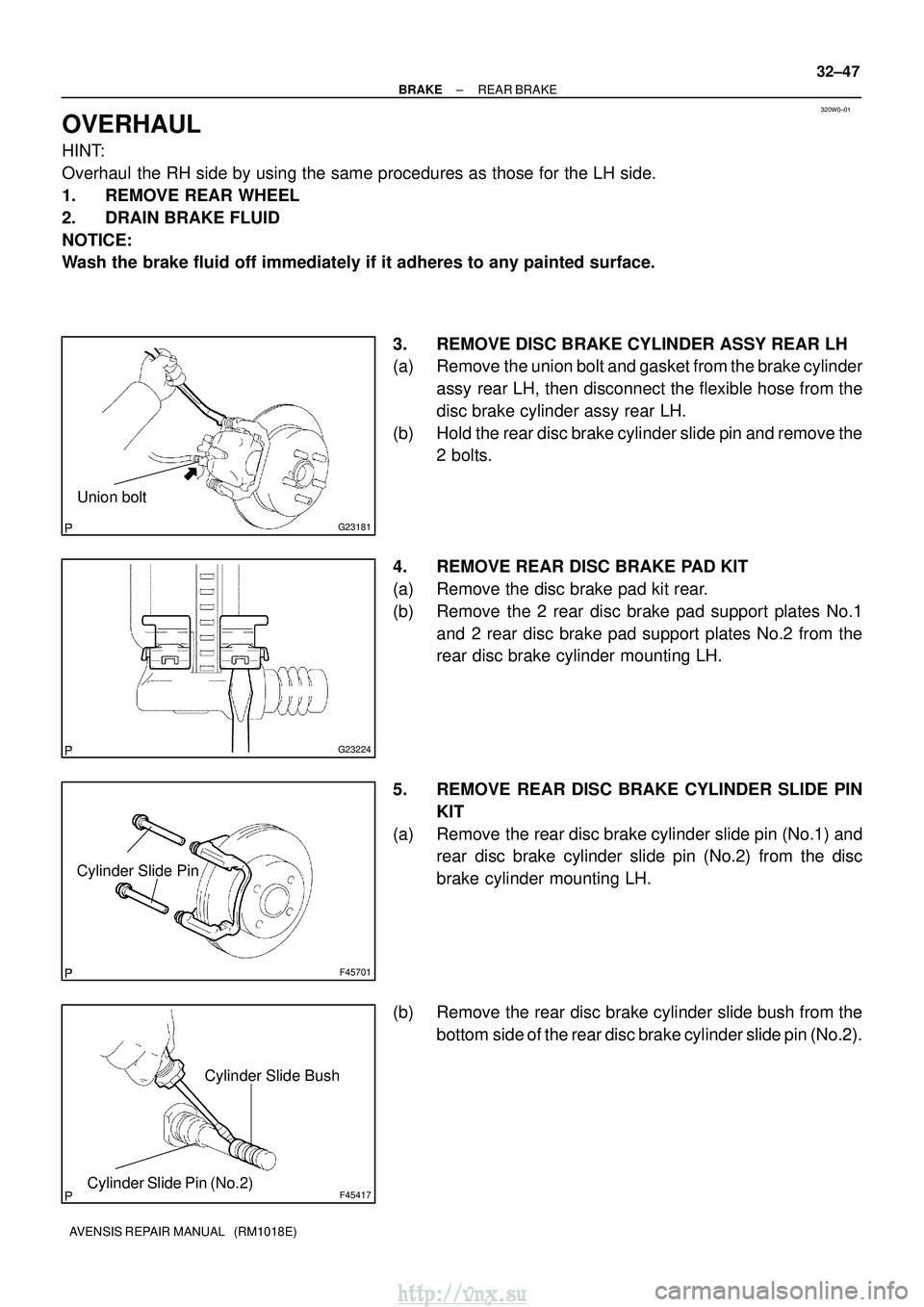
OVERHAUL
HINT:
Overhaul the RH side by using the same procedures as those for the LH side.
1. REMOVE REAR WHEEL
2. DRAIN BRAKE FLUID
NOTICE:
Wash the brake fluid off immediately if it adheres to any painted surface\
.
3. REMOVE DISC BRAKE CYLINDER ASSY REAR LH
(a) Remove the union bolt and gasket from the brake cylinderassy rear LH, then disconnect the flexible hose from the
disc brake cylinder assy rear LH.
(b) Hold the rear disc brake cylinder slide pin and remove the 2 bolts.
4. REMOVE REAR DISC BRAKE PAD KIT
(a) Remove the disc brake pad kit rear.
(b) Remove the 2 rear disc brake pad support plates No.1 and 2 rear disc brake pad support plates No.2 from the
rear disc brake cylinder mounting LH.
5. REMOVE REAR DISC BRAKE CYLINDER SLIDE PIN KIT
(a) Remove the rear disc brake cylinder slide pin (No.1) and rear disc brake cylinder slide pin (No.2) from the disc
brake cylinder mounting LH.
(b) Remove the rear disc brake cylinder slide bush from the bottom side of the rear disc brake cylinder slide pin (No.2).
http://vnx.su
Page 1120 of 2234
320VV±01
G23167
F08657
BoltSST
SST
Bolt
±
BRAKE SKID CONTROL SENSOR
32±61
AVENSIS REPAIR MANUAL (RM1018E)
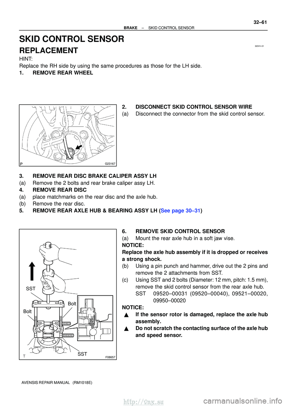
SKID CONTROL SENSOR
REPLACEMENT
HINT:
Replace the RH side by using the same procedures as those for the LH side.
1. REMOVE REAR WHEEL
2. DISCONNECT SKID CONTROL SENSOR WIRE
(a) Disconnect the connector from the skid control sensor.
3. REMOVE REAR DISC BRAKE CALIPER ASSY LH
(a) Remove the 2 bolts and rear brake caliper assy LH.
4. REMOVE REAR DISC
(a) place matchmarks on the rear disc and the axle hub.
(b) Remove the rear disc.
5.REMOVE REAR AXLE HUB & BEARING ASSY LH (See page 30±31) 6. REMOVE SKID CONTROL SENSOR
(a) Mount the rear axle hub in a soft jaw vise.
NOTICE:
Replace the axle hub assembly if it is dropped or receives
a strong shock.
(b) Using a pin punch and hammer, drive out the 2 pins andremove the 2 attachments from SST.
(c) Using SST and 2 bolts (Diameter: 12 mm, pitch: 1.5 mm), remove the skid control sensor from the rear axle hub.
SST 09520±00031 (09520±00040), 09521±00020, 09950±00020
NOTICE:
�If the sensor rotor is damaged, replace the axle hub
assembly.
�Do not scratch the contacting surface of the axle hub
and speed sensor.
http://vnx.su
Page 1121 of 2234
G23168
F08658
SST
G23167
32±62
±
BRAKE SKID CONTROL SENSOR
AVENSIS REPAIR MANUAL (RM1018E)
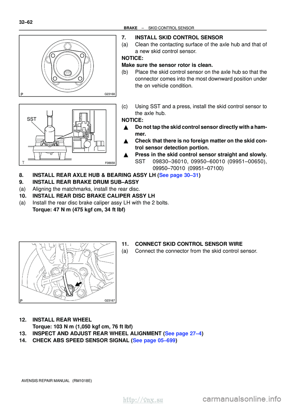
7. INSTALL SKID CONTROL SENSOR
(a) Clean the contacting surface of the axle hub and that of a new skid control sensor.
NOTICE:
Make sure the sensor rotor is clean.
(b) Place the skid control sensor on the axle hub so that the connector comes into the most downward position under
the on vehicle condition.
(c) Using SST and a press, install the skid control sensor to the axle hub.
NOTICE:
�Do not tap the skid control sensor directly with a ham-
mer.
�Check that there is no foreign matter on the skid con-
trol sensor detection portion.
�Press in the skid control sensor straight and slowly.
SST 09830±36010, 09950±60010 (09951±00650), 09950±70010 (09951±07100)
8.INSTALL REAR AXLE HUB & BEARING ASSY LH (See page 30±31)
9. INSTALL REAR BRAKE DRUM SUB±ASSY
(a) Aligning the matchmarks, install the rear disc.
10. INSTALL REAR DISC BRAKE CALIPER ASSY LH
(a) Install the rear disc brake caliper assy LH with the 2 bolts. Torque: 47 N �m (475 kgf� cm, 34 ft�lbf)
11. CONNECT SKID CONTROL SENSOR WIRE
(a) Connect the connector from the skid control sensor.
12. INSTALL REAR WHEEL Torque: 103 N� m (1,050 kgf�cm, 76 ft �lbf)
13.INSPECT AND ADJUST REAR WHEEL ALIGNMENT (See page 27±4)
14.CHECK ABS SPEED SENSOR SIGNAL (See page 05±699)
http://vnx.su