Page 1025 of 2234
G23868
G23867
G25772
G25771
27±12
±
REAR SUSPENSION REAR SHOCK ABSORBER WITH COIL SPRING
AVENSIS REPAIR MANUAL (RM1018E)
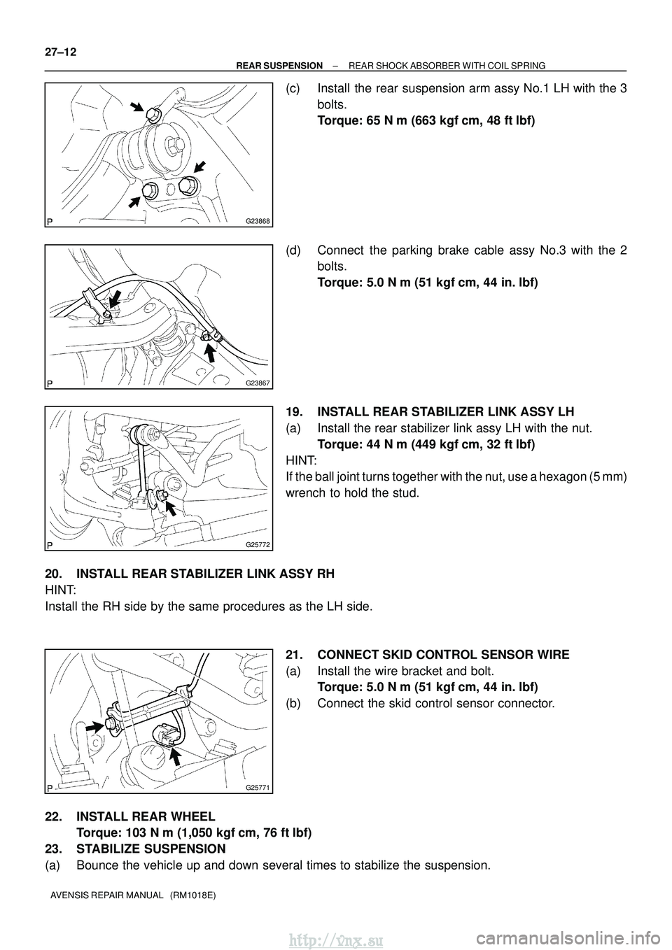
(c) Install the rear suspension arm assy No.1 LH with the 3 bolts.
Torque: 65 N �m (663 kgf� cm, 48 ft�lbf)
(d) Connect the parking brake cable assy No.3 with the 2 bolts.
Torque: 5.0 N� m (51 kgf�cm, 44 in. �lbf)
19. INSTALL REAR STABILIZER LINK ASSY LH
(a) Install the rear stabilizer link assy LH with the nut. Torque: 44 N �m (449 kgf� cm, 32 ft�lbf)
HINT:
If the ball joint turns together with the nut, use a hexagon (5 mm)
wrench to hold the stud.
20. INSTALL REAR STABILIZER LINK ASSY RH
HINT:
Install the RH side by the same procedures as the LH side. 21. CONNECT SKID CONTROL SENSOR WIRE
(a) Install the wire bracket and bolt.Torque: 5.0 N �m (51 kgf �cm, 44 in. �lbf)
(b) Connect the skid control sensor connector.
22. INSTALL REAR WHEEL Torque: 103 N� m (1,050 kgf�cm, 76 ft �lbf)
23. STABILIZE SUSPENSION
(a) Bounce the vehicle up and down several times to stabilize the suspension\
.
http://vnx.su
Page 1030 of 2234
270E3±01
G23867
G25771
G25772
G25775
±
REAR SUSPENSION REAR SUSPENSION ARM ASSY NO.1 LH
27±15
AVENSIS REPAIR MANUAL (RM1018E)
REAR SUSPENSION ARM ASSY NO.1 LH
OVERHAUL
HINT:
COMPONENTS: See page 27±2.
1. REMOVE REAR WHEEL
2. SEPARATE PARKING BRAKE CABLE ASSY NO.3
(a) Remove the 2 bolts, and separate the parking brake cableassy No.3.
3. DISCONNECT SKID CONTROL SENSOR WIRE
(a) Disconnect the skid control sensor connector.
(b) Remove the bolt and wire bracket.
4. SEPARATE REAR STABILIZER LINK ASSY LH
(a) Remove the nut, and separate the rear stabilizer link assy LH.
HINT:
If the ball joint turns together with the nut, use a hexagon (5 mm)
wrench to hold the stud.
5. REMOVE LOWER CONTROL ARM ASSY LH
(a) Support the rear suspension arm assy No.1 LH.
http://vnx.su
Page 1045 of 2234
G23878
Inner side
Stopper Ring
G23876
G25774
27±30
±
REAR SUSPENSION STABILIZER BAR REAR
AVENSIS REPAIR MANUAL (RM1018E)
5. INSTALL STABILIZER BAR REAR
(a) Install the 2 stabilizer bush rear to each stabilizer bar rear.
HINT:
Install the stabilizer bush rear to the outer side of the stopper
ring on the stabilizer bar.
(b) Install the stabilizer bar rear and 2 rear stabilizer bar bracket No.3 with 2 bolts and 2 nuts.
Torque: 35 N �m (357 kgf� cm, 26 ft�lbf)
6. INSTALL REAR STABILIZER LINK ASSY LH
(a) Install the rear stabilizer link assy LH with the 2 nuts. Torque: 44 N �m (449 kgf� cm, 32 ft�lbf)
HINT:
If the ball joint turns together with the nut, use a hexagon (5 mm)
wrench to hold the stud.
7. INSTALL REAR STABILIZER LINK ASSY RH
HINT:
Install the RH side by the same procedures as the LH side.
8.INSPECT AND ADJUST REAR WHEEL ALIGNMENT (See page 27±4)
http://vnx.su
Page 1053 of 2234
300JY±01
������F45751
SST
C80291
F44775
C67088
30±22
±
DRIVE SHAFT / PROPELLER SHAFT FRONT AXLE HUB SUB±ASSY LH
AVENSIS REPAIR MANUAL (RM1018E)
REPLACEMENT
HINT:
Replace the RH side by the same procedures as the LH side.
1. REMOVE FRONT WHEEL
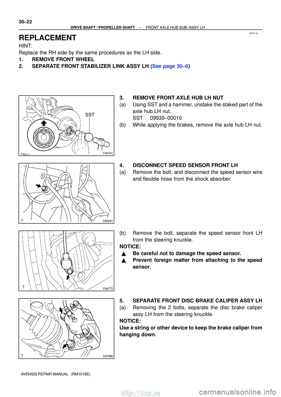
2.SEPARATE FRONT STABILIZER LINK ASSY LH (See page 30±6) 3. REMOVE FRONT AXLE HUB LH NUT
(a) Using SST and a hammer, unstake the staked part of theaxle hub LH nut.
SST 09930±00010
(b) While applying the brakes, remove the axle hub LH nut.
4. DISCONNECT SPEED SENSOR FRONT LH
(a) Remove the bolt, and disconnect the speed sensor wire and flexible hose from the shock absorber.
(b) Remove the bolt, separate the speed sensor front LH from the steering knuckle.
NOTICE:
�Be careful not to damage the speed sensor.
�Prevent foreign matter from attaching to the speed
sensor.
5. SEPARATE FRONT DISC BRAKE CALIPER ASSY LH
(a) Removing the 2 bolts, separate the disc brake caliper assy LH from the steering knuckle.
NOTICE:
Use a string or other device to keep the brake caliper from
hanging down.
http://vnx.su
Page 1065 of 2234
300JZ±01
������F45267
F44818
������F45752
SST
±
DRIVE SHAFT / PROPELLER SHAFT REAR AXLE CARRIER SUB±ASSY LH
30±31
AVENSIS REPAIR MANUAL (RM1018E)
REPLACEMENT
HINT:
Replace the RH side by the same procedures as the LH side.
1. INSPECT REAR AXLE CARRIER SUB±ASSY LH
(a) Check that there is no looseness on the ball joint by shaking the lower arm up and down with a force
of 294 N (30kgf, 66 lbf).
2. REMOVE REAR WHEEL
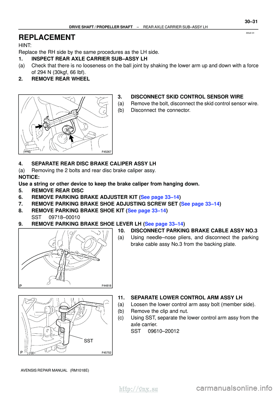
3. DISCONNECT SKID CONTROL SENSOR WIRE
(a) Remove the bolt, disconnect the skid control sensor wire.
(b) Disconnect the connector.
4. SEPARATE REAR DISC BRAKE CALIPER ASSY LH
(a) Removing the 2 bolts and rear disc brake caliper assy.
NOTICE:
Use a string or other device to keep the brake caliper from hanging down\
.
5. REMOVE REAR DISC
6.REMOVE PARKING BRAKE ADJUSTER KIT (See page 33±14)
7.REMOVE PARKING BRAKE SHOE ADJUSTING SCREW SET (See page 33±14)
8.REMOVE PARKING BRAKE SHOE KIT (See page 33±14) SST 09718±00010
9.REMOVE PARKING BRAKE SHOE LEVER LH (See page 33±14)
10. DISCONNECT PARKING BRAKE CABLE ASSY NO.3
(a) Using needle±nose pliers, and disconnect the parkingbrake cable assy No.3 from the backing plate.
11. SEPARATE LOWER CONTROL ARM ASSY LH
(a) Loosen the lower control arm assy bolt (member side).
(b) Remove the clip and nut.
(c) Using SST, separate the lower control arm assy from the axle carrier.
SST 09610±20012
http://vnx.su
Page 1068 of 2234
G21543
F44820
������F45267
30±34
±
DRIVE SHAFT / PROPELLER SHAFTREAR AXLE CARRIER SUB±ASSY LH
AVENSIS REPAIR MANUAL (RM1018E)
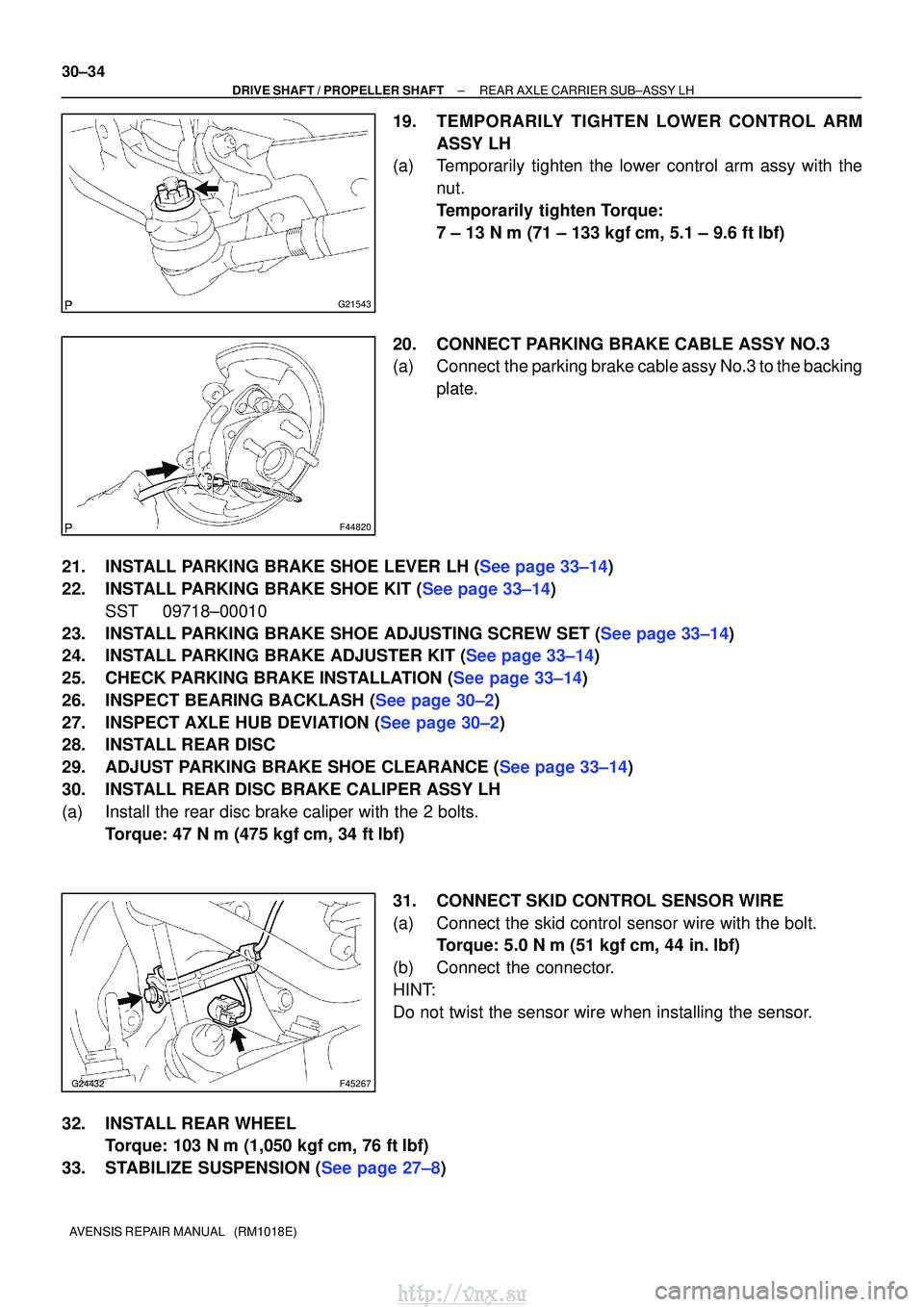
19.TEMPORARILY TIGHTEN LOWER CONTROL ARM ASSY LH
(a)Temporarily tighten the lower control arm assy with the
nut.
Temporarily tighten Torque:
7 ± 13 N�m (71 ± 133 kgf �cm, 5.1 ± 9.6 ft�lbf)
20.CONNECT PARKING BRAKE CABLE ASSY NO.3
(a)Connect the parking brake cable assy No.3 to the backing plate.
21.INSTALL PARKING BRAKE SHOE LEVER LH (See page 33±14)
22.INSTALL PARKING BRAKE SHOE KIT (See page 33±14) SST 09718±00010
23.INSTALL PARKING BRAKE SHOE ADJUSTING SCREW SET (See page 33±14)
24.INSTALL PARKING BRAKE ADJUSTER KIT (See page 33±14)
25.CHECK PARKING BRAKE INSTALLATION (See page 33±14)
26.INSPECT BEARING BACKLASH (See page 30±2)
27.INSPECT AXLE HUB DEVIATION (See page 30±2)
28. INSTALL REAR DISC
29.ADJUST PARKING BRAKE SHOE CLEARANCE (See page 33±14)
30. INSTALL REAR DISC BRAKE CALIPER ASSY LH
(a) Install the rear disc brake caliper with the 2 bolts. Torque: 47 N �m (475 kgf� cm, 34 ft�lbf)
31. CONNECT SKID CONTROL SENSOR WIRE
(a) Connect the skid control sensor wire with the bolt. Torque: 5.0 N �m (51 kgf �cm, 44 in. �lbf)
(b) Connect the connector.
HINT:
Do not twist the sensor wire when installing the sensor.
32. INSTALL REAR WHEEL Torque: 103 N� m (1,050 kgf�cm, 76 ft �lbf)
33.STABILIZE SUSPENSION (See page 27±8)
http://vnx.su
Page 1070 of 2234
300K0±01
������F45577
Hold
Turn
SST
������F45578
Hold
Turn
Nut
Washer
30±36
±
DRIVE SHAFT / PROPELLER SHAFT REAR AXLE LH HUB BOLT
AVENSIS REPAIR MANUAL (RM1018E)
REAR AXLE LH HUB BOLT
REPLACEMENT
HINT:
�COMPONENTS: See page 30±30
�Replace the RH side by the same procedures as the LH side.
1. REMOVE REAR WHEEL
2. SEPARATE REAR DISC BRAKE CALIPER ASSY LH
(a) Removing the 2 bolts and rear disc brake caliper assy.
NOTICE:
Use a string or other device to keep the brake caliper from hanging down\
.
3. REMOVE REAR DISC
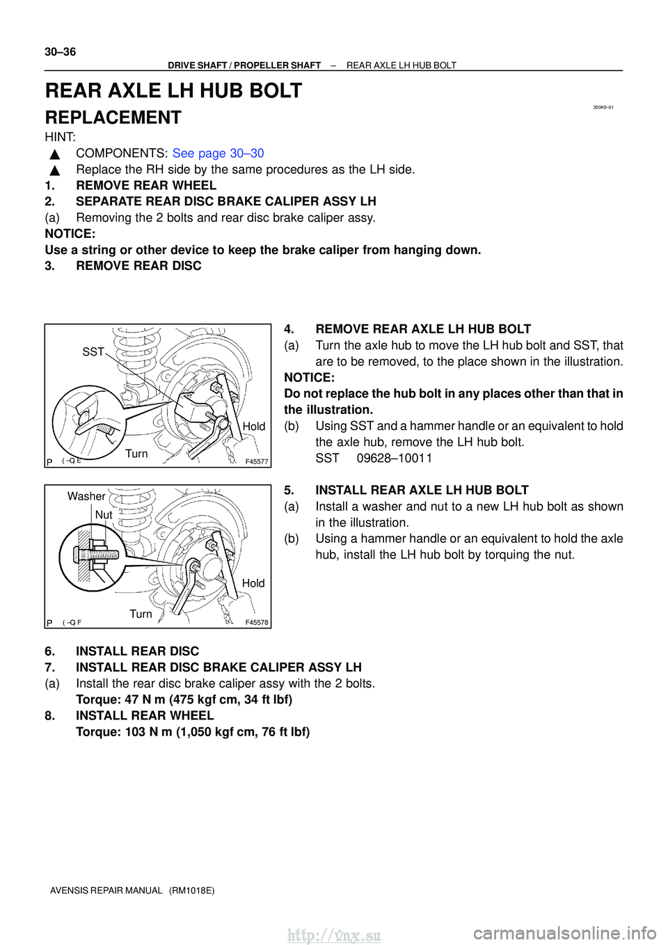
4. REMOVE REAR AXLE LH HUB BOLT
(a) Turn the axle hub to move the LH hub bolt and SST, thatare to be removed, to the place shown in the illustration.
NOTICE:
Do not replace the hub bolt in any places other than that in
the illustration.
(b) Using SST and a hammer handle or an equivalent to hold the axle hub, remove the LH hub bolt.
SST 09628±10011
5. INSTALL REAR AXLE LH HUB BOLT
(a) Install a washer and nut to a new LH hub bolt as shown in the illustration.
(b) Using a hammer handle or an equivalent to hold the axle
hub, install the LH hub bolt by torquing the nut.
6. INSTALL REAR DISC
7. INSTALL REAR DISC BRAKE CALIPER ASSY LH
(a) Install the rear disc brake caliper assy with the 2 bolts. Torque: 47 N �m (475 kgf� cm, 34 ft�lbf)
8. INSTALL REAR WHEEL Torque: 103 N� m (1,050 kgf�cm, 76 ft �lbf)
http://vnx.su
Page 1073 of 2234
320VZ±01
G24211
To Master Cylinder Front
G24212
To Master Cylinder Rear
To Front Wheel RH
To Rear Wheel LH
To Rear Wheel RH
To Front Wheel LH
G24213
32±54
±
BRAKE BRAKE ACTUATOR ASSY (W/O VSC)
AVENSIS REPAIR MANUAL (RM1018E)
REPLACEMENT
1. DRAIN BRAKE FLUID
NOTICE:
Wash the brake fluid off immediately if it adheres to any painted surface\
s.
2. REMOVE FRONT WHEEL RH
3. REMOVE FRONT FENDER LINER RH 4. REMOVE BRAKE ACTUATOR WITH BRACKET
(a) Release the latch of the brake actuator connector to dis-connect the connector.
(b) Using SST, disconnect the brake tubes from the brake ac- tuator.
SST 09023±00100
(c) Use tags or make a memo to identify the place to recon- nect.
(d) Remove the nut, 2 bolts and brake actuator with bracket.
http://vnx.su