Page 936 of 2234
A56703
Seal Width
4 to 7 mm
A
AB
B
A56697
AA
A
A AA
B
B
D
B
B
B
BC
C
C
CC
CC D
D
A56696
±
LUBRICATION OIL PUMP ASSY (1CD±FTV)
17±27
AVENSIS REPAIR MANUAL (RM1018E)
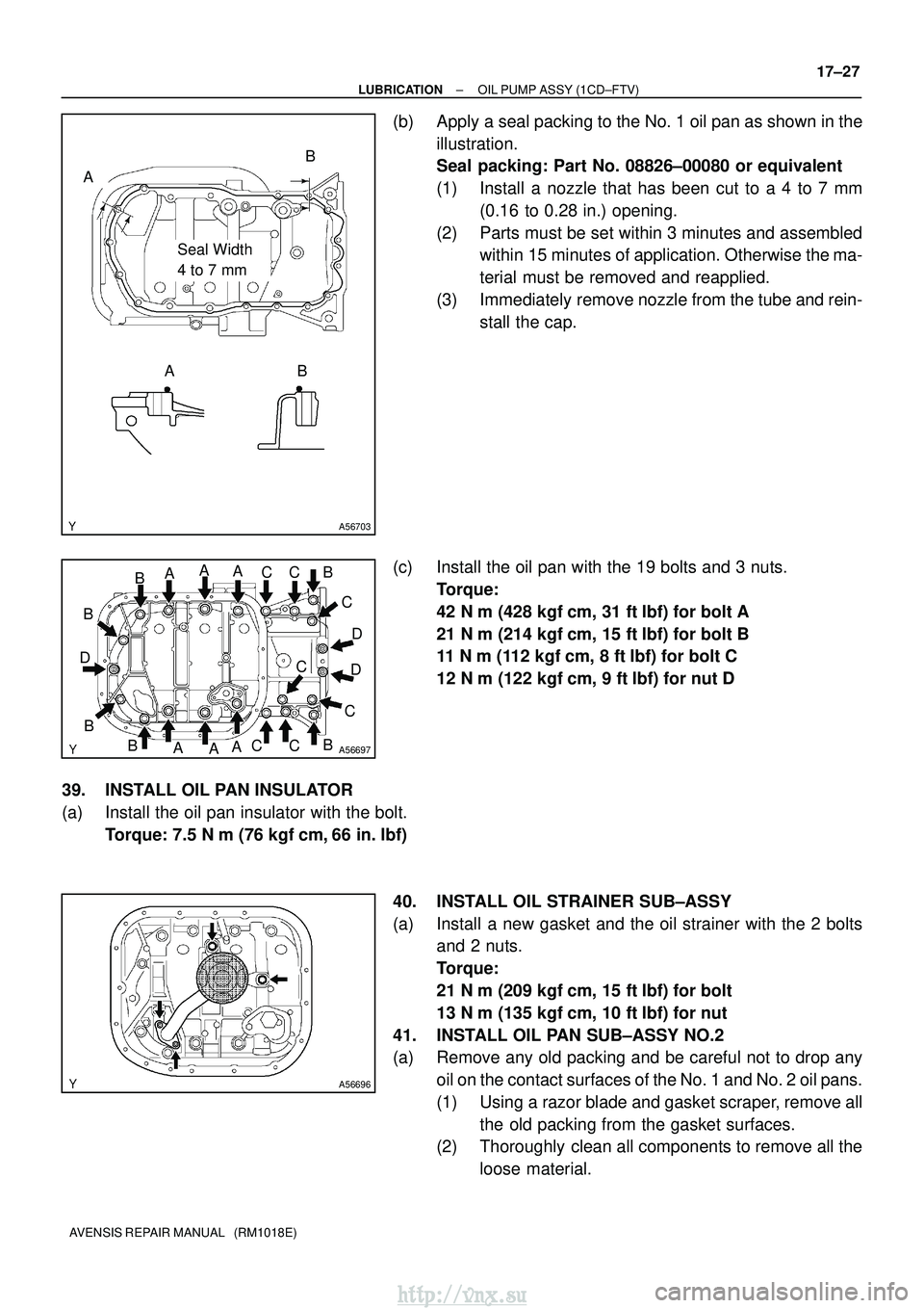
(b) Apply a seal packing to the No. 1 oil pan as shown in the
illustration.
Seal packing: Part No. 08826±00080 or equivalent
(1) Install a nozzle that has been cut to a 4 to 7 mm(0.16 to 0.28 in.) opening.
(2) Parts must be set within 3 minutes and assembled within 15 minutes of application. Otherwise the ma-
terial must be removed and reapplied.
(3) Immediately remove nozzle from the tube and rein- stall the cap.
(c) Install the oil pan with the 19 bolts and 3 nuts. Torque:
42 N�m (428 kgf� cm, 31 ft�lbf) for bolt A
21 N� m (214 kgf� cm, 15 ft�lbf) for bolt B
11 N �m (112 kgf �cm, 8 ft� lbf) for bolt C
12 N� m (122 kgf� cm, 9 ft�lbf) for nut D
39. INSTALL OIL PAN INSULATOR
(a) Install the oil pan insulator with the bolt. Torque: 7.5 N �m (76 kgf �cm, 66 in. �lbf)
40. INSTALL OIL STRAINER SUB±ASSY
(a) Install a new gasket and the oil strainer with the 2 bolts and 2 nuts.
Torque:
21 N�m (209 kgf� cm, 15 ft�lbf) for bolt
13 N� m (135 kgf� cm, 10 ft�lbf) for nut
41. INSTALL OIL PAN SUB±ASSY NO.2
(a) Remove any old packing and be careful not to drop any oil on the contact surfaces of the No. 1 and No. 2 oil pans.
(1) Using a razor blade and gasket scraper, remove allthe old packing from the gasket surfaces.
(2) Thoroughly clean all components to remove all the
loose material.
http://vnx.su
Page 938 of 2234
SST
A09583
Inward
Angle Sensor
±
LUBRICATIONOIL PUMP ASSY(1CD±FTV)
17±29
AVENSIS REPAIR MANUAL (RM1018E)
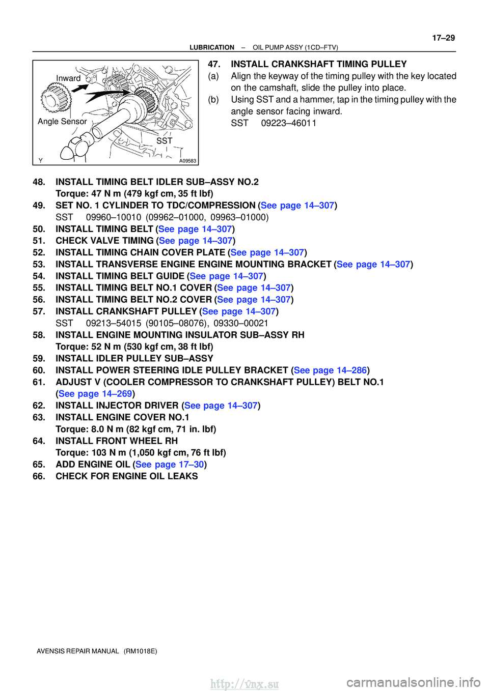
47.INSTALL CRANKSHAFT TIMING PULLEY
(a)Align the keyway of the timing pulley with the key located
on the camshaft, slide the pulley into place.
(b)Using SST and a hammer, tap in the timing pulley with the angle sensor facing inward.
SST09223±46011
48.INSTALL TIMING BELT IDLER SUB±ASSY NO.2 Torque: 47 N �m (479 kgf�cm,35 ft�lbf)
49.SET NO. 1 CYLINDER TO TDC/COMPRESSION(See page 14±307) SST 09960±10010 (09962±01000, 09963±01000)
50.INSTALL TIMING BELT(See page 14±307)
51.CHECK VALVE TIMING(See page 14±307)
52.INSTALL TIMING CHAIN COVER PLATE(See page 14±307)
53.INSTALL TRANSVERSE ENGINE ENGINE MOUNTING BRACKET(See page 14±307)
54.INSTALL TIMING BELT GUIDE(See page 14±307)
55.INSTALL TIMING BELT NO.1 COVER(See page 14±307)
56.INSTALL TIMING BELT NO.2 COVER(See page 14±307)
57.INSTALL CRANKSHAFT PULLEY(See page 14±307) SST 09213±54015 (90105±08076), 09330±00021
58. INSTALL ENGINE MOUNTING INSULATOR SUB±ASSY RH Torque: 52 N �m (530 kgf� cm, 38 ft�lbf)
59. INSTALL IDLER PULLEY SUB±ASSY
60.INSTALL POWER STEERING IDLE PULLEY BRACKET (See page 14±286)
61. ADJUST V (COOLER COMPRESSOR TO CRANKSHAFT PULLEY) BELT NO.1 (See page 14±269)
62.INSTALL INJECTOR DRIVER (See page 14±307)
63. INSTALL ENGINE COVER NO.1 Torque: 8.0 N �m (82 kgf �cm, 71 in. �lbf)
64. INSTALL FRONT WHEEL RH Torque: 103 N� m (1,050 kgf�cm, 76 ft �lbf)
65.ADD ENGINE OIL(See page 17±30)
66. CHECK FOR ENGINE OIL LEAKS
http://vnx.su
Page 946 of 2234
1807N±01
A50033
P03783
P03792
IG0147
Ohmmeter
Ground
±
IGNITION IGNITION SYSTEM (1AZ±FE)
18±9
AVENSIS REPAIR MANUAL (RM1018E)
INSPECTION
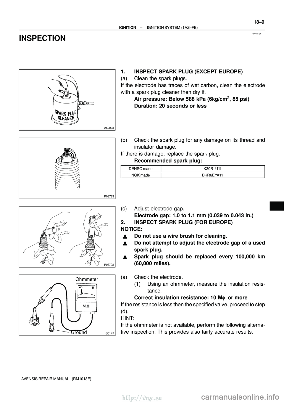
1. INSPECT SPARK PLUG (EXCEPT EUROPE)
(a) Clean the spark plugs.
If the electrode has traces of wet carbon, clean the electrode
with a spark plug cleaner then dry it.
Air pressure: Below 588 kPa (6kg/cm
2, 85 psi)
Duration: 20 seconds or less
(b) Check the spark plug for any damage on its thread and insulator damage.
If there is damage, replace the spark plug. Recommended spark plug:
DENSO madeK20R±U11
NGK madeBKR6EYA11
(c) Adjust electrode gap.Electrode gap: 1.0 to 1.1 mm (0.039 to 0.043 in.)
2. INSPECT SPARK PLUG (FOR EUROPE)
NOTICE:
�Do not use a wire brush for cleaning.
�Do not attempt to adjust the electrode gap of a used
spark plug.
�Spark plug should be replaced every 100,000 km
(60,000 miles).
(a) Check the electrode. (1) Using an ohmmeter, measure the insulation resis-tance.
Correct insulation resistance: 10 M� or more
If the resistance is less then the specified valve, proceed to step
(d).
HINT:
If the ohmmeter is not available, perform the following alterna-
tive inspection. This provides also fairly accurate results.
http://vnx.su
Page 947 of 2234
B01301
IG0316
B02101
1.1 mm
B62019
18±10
±
IGNITION IGNITION SYSTEM (1AZ±FE)
AVENSIS REPAIR MANUAL (RM1018E)
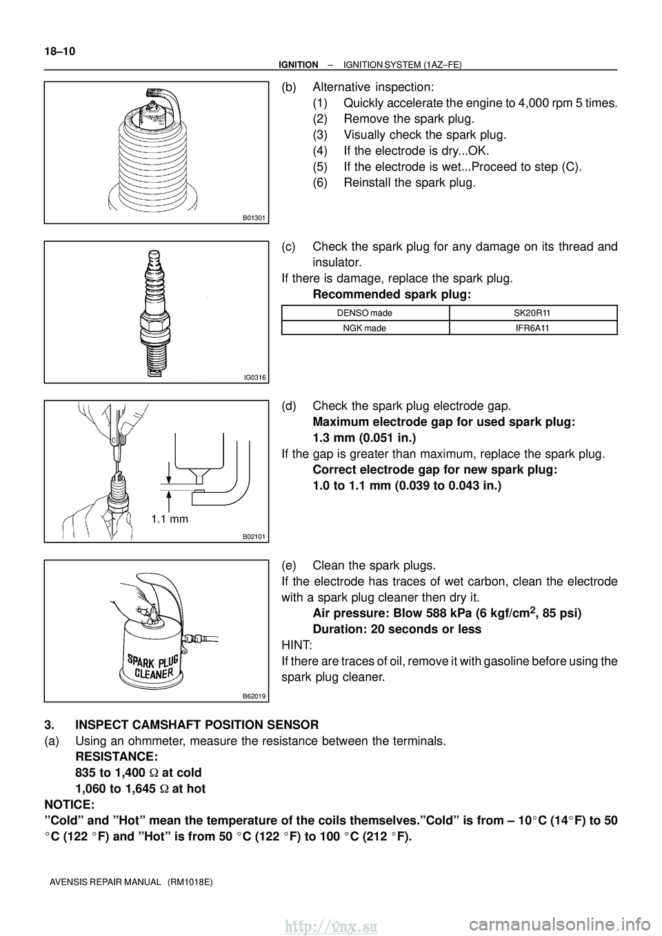
(b) Alternative inspection: (1) Quickly accelerate the engine to 4,000 rpm 5 times.
(2) Remove the spark plug.
(3) Visually check the spark plug.
(4) If the electrode is dry...OK.
(5) If the electrode is wet...Proceed to step (C).
(6) Reinstall the spark plug.
(c) Check the spark plug for any damage on its thread and insulator.
If there is damage, replace the spark plug. Recommended spark plug:
DENSO madeSK20R11
NGK madeIFR6A11
(d) Check the spark plug electrode gap.Maximum electrode gap for used spark plug:
1.3 mm (0.051 in.)
If the gap is greater than maximum, replace the spark plug. Correct electrode gap for new spark plug:
1.0 to 1.1 mm (0.039 to 0.043 in.)
(e) Clean the spark plugs.
If the electrode has traces of wet carbon, clean the electrode
with a spark plug cleaner then dry it. Air pressure: Blow 588 kPa (6 kgf/cm
2, 85 psi)
Duration: 20 seconds or less
HINT:
If there are traces of oil, remove it with gasoline before using the
spark plug cleaner.
3. INSPECT CAMSHAFT POSITION SENSOR
(a) Using an ohmmeter, measure the resistance between the terminals. RESISTANCE:
835 to 1,400 � at cold
1,060 to 1,645 �at hot
NOTICE:
ºColdº and ºHotº mean the temperature of the coils themselve\
s.ºColdº is from ± 10 �C (14� F) to 50
� C (122 �F) and ºHotº is from 50 � C (122 �F) to 100 � C (212 �F).
http://vnx.su
Page 951 of 2234
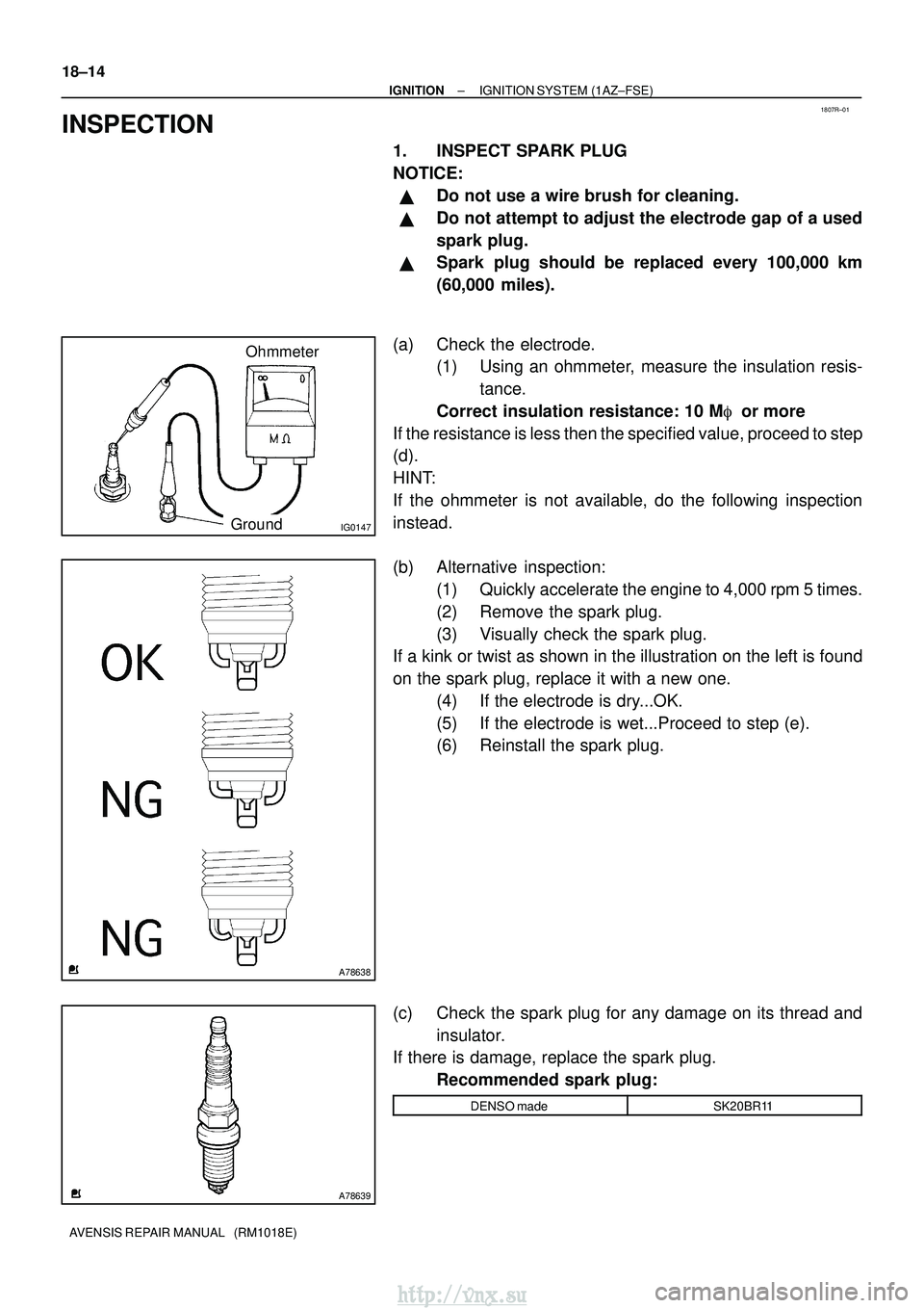
1807R±01
IG0147
Ohmmeter
Ground
A78638
A78639
18±14
±
IGNITION IGNITION SYSTEM (1AZ±FSE)
AVENSIS REPAIR MANUAL (RM1018E)
INSPECTION
1. INSPECT SPARK PLUG
NOTICE:
�Do not use a wire brush for cleaning.
�Do not attempt to adjust the electrode gap of a used
spark plug.
�Spark plug should be replaced every 100,000 km
(60,000 miles).
(a) Check the electrode. (1) Using an ohmmeter, measure the insulation resis-
tance.
Correct insulation resistance: 10 M� or more
If the resistance is less then the specified value, proceed to step
(d).
HINT:
If the ohmmeter is not available, do the following inspection
instead.
(b) Alternative inspection: (1) Quickly accelerate the engine to 4,000 rpm 5 times.
(2) Remove the spark plug.
(3) Visually check the spark plug.
If a kink or twist as shown in the illustration on the left is found
on the spark plug, replace it with a new one.
(4) If the electrode is dry...OK.
(5) If the electrode is wet...Proceed to step (e).
(6) Reinstall the spark plug.
(c) Check the spark plug for any damage on its thread and insulator.
If there is damage, replace the spark plug.
Recommended spark plug:
DENSO madeSK20BR11
http://vnx.su
Page 955 of 2234
1807P±01
A50033
P03783
P03792
±
IGNITION IGNITION SYSTEM (1ZZ±FE/3ZZ±FE)
18±3
AVENSIS REPAIR MANUAL (RM1018E)
INSPECTION
1. INSPECT SPARK PLUG
(a) Clean the spark plugs.
If the electrode has traces of wet carbon, clean the electrode
with a spark plug cleaner then dry it.
Air pressure: Below 588 kPa (6kg/cm
2, 85 psi)
Duration: 20 seconds or less
(b) Check the spark plug for any damage on its thread and insulator damage.
If there is damage, replace the spark plug. Recommended spark plug:
DENSO madeK16R±U11
NGK madeBKR5EYA11
(c) Adjust electrode gap.Electrode gap: 1.0 to 1.1 mm (0.039 to 0.043 in.)
2. INSPECT CAMSHAFT POSITION SENSOR
(a) Using an ohmmeter, measure the resistance between the terminals. RESISTANCE:
835 to 1,400 � at cold
1,060 to 1,645 �at hot
NOTICE:
ºColdº and ºHotº mean the temperature of the coils themselve\
s.ºColdº is from ± 10 �C (14� F) to 50
� C (122 �F) and ºHotº is from 50 � C (122 �F) to 100 � C (212 �F).
http://vnx.su
Page 991 of 2234
28mm
F44963
F40270
SST
F08624
SST
±
FRONT SUSPENSION FRONT SHOCK ABSORBER WITH COIL SPRING
26±11
AVENSIS REPAIR MANUAL (RM1018E)
4. FIX FRONT SHOCK ABSORBER WITH COIL SPRING
(a) Install 2 nuts and a bolt to the bracket at the lower side of
the shock absorber and secure it in a vise.
5. REMOVE FRONT SUSPENSION SUPPORT DUST COVER LH 6. REMOVE FRONT SUPPORT TO FRONT SHOCKABSORBER LH NUT
(a) Using SST, compress the coil spring. SST 09727±30021
NOTICE:
Do not use an impact wrench. It will damage the SST.
(b) Remove the front suspension support dust cover from the
suspension support.
(c) Using SST to hold the spring seat, remove the nut. SST 09729±22031
7. REMOVE FRONT SUSPENSION SUPPORT SUB±ASSY LH
8. REMOVE FRONT SUSPENSION SUPPORT LH DUST SEAL
9. REMOVE FRONT COIL SPRING SEAT UPPER LH
10. REMOVE FRONT COIL SPRING INSULATOR UPPER LH
11. REMOVE FRONT COIL SPRING LH
12. REMOVE FRONT SPRING BUMPER LH
13. REMOVE FRONT COIL SPRING INSULATOR LOWER LH
http://vnx.su
Page 992 of 2234
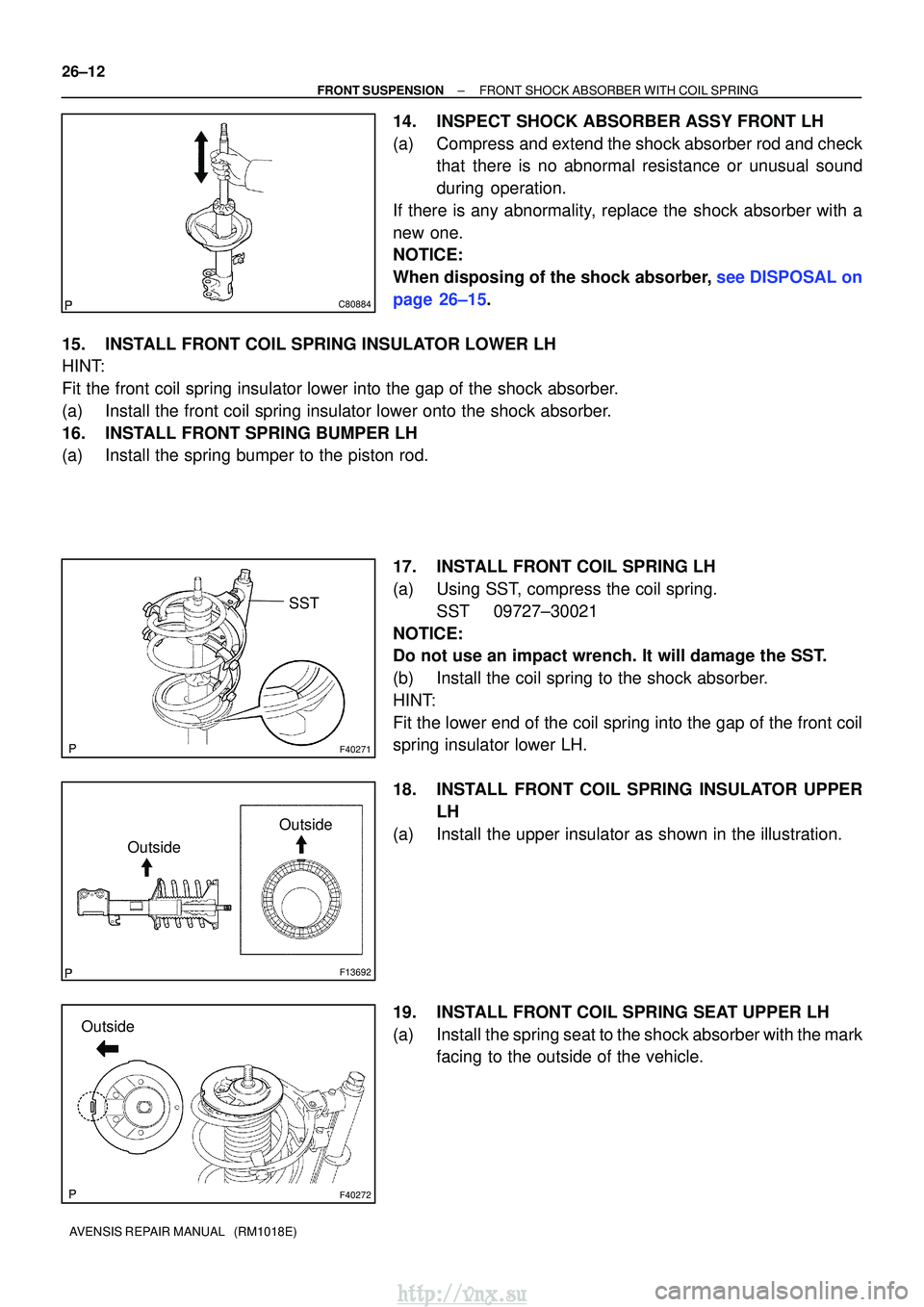
C80884
F40271
SST
F13692
OutsideOutside
F40272
Outside
26±12
±
FRONT SUSPENSION FRONT SHOCK ABSORBER WITH COIL SPRING
AVENSIS REPAIR MANUAL (RM1018E)
14. INSPECT SHOCK ABSORBER ASSY FRONT LH
(a) Compress and extend the shock absorber rod and check that there is no abnormal resistance or unusual sound
during operation.
If there is any abnormality, replace the shock absorber with a
new one.
NOTICE:
When disposing of the shock absorber, see DISPOSAL on
page 26±15.
15. INSTALL FRONT COIL SPRING INSULATOR LOWER LH
HINT:
Fit the front coil spring insulator lower into the gap of the shock abso\
rber.
(a) Install the front coil spring insulator lower onto the shock absorber.
16. INSTALL FRONT SPRING BUMPER LH
(a) Install the spring bumper to the piston rod.
17. INSTALL FRONT COIL SPRING LH
(a) Using SST, compress the coil spring.SST 09727±30021
NOTICE:
Do not use an impact wrench. It will damage the SST.
(b) Install the coil spring to the shock absorber.
HINT:
Fit the lower end of the coil spring into the gap of the front coil
spring insulator lower LH.
18. INSTALL FRONT COIL SPRING INSULATOR UPPER LH
(a) Install the upper insulator as shown in the illustration.
19. INSTALL FRONT COIL SPRING SEAT UPPER LH
(a) Install the spring seat to the shock absorber with the mark facing to the outside of the vehicle.
http://vnx.su