Page 689 of 2234
A76718
A76719
A62838SST
A62838SST
±
ENGINE MECHANICAL PARTIAL ENGINE ASSY (1ZZ±FE/3ZZ±FE)
14±33
AVENSIS REPAIR MANUAL (RM1018E)
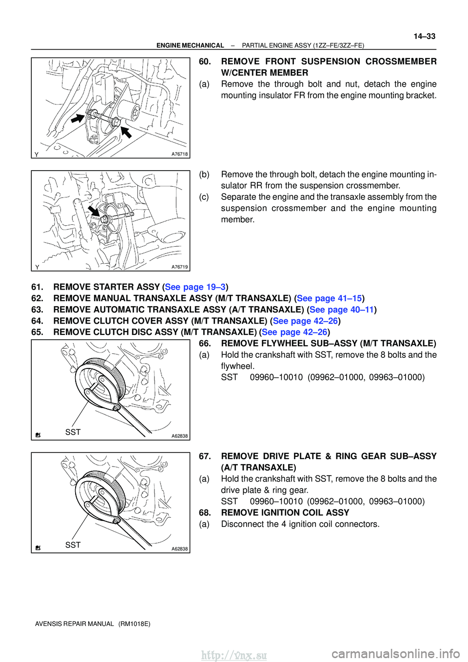
60. REMOVE FRONT SUSPENSION CROSSMEMBER
W/CENTER MEMBER
(a) Remove the through bolt and nut, detach the engine
mounting insulator FR from the engine mounting bracket.
(b) Remove the through bolt, detach the engine mounting in- sulator RR from the suspension crossmember.
(c) Separate the engine and the transaxle assembly from the suspension crossmember and the engine mounting
member.
61.REMOVE STARTER ASSY(See page 19±3)
62.REMOVE MANUAL TRANSAXLE ASSY (M/T TRANSAXLE) (See page 41±15)
63.REMOVE AUTOMATIC TRANSAXLE ASSY (A/T TRANSAXLE) (See page 40±11)
64.REMOVE CLUTCH COVER ASSY (M/T TRANSAXLE) (See page 42±26)
65.REMOVE CLUTCH DISC ASSY (M/T TRANSAXLE)(See page 42±26) 66. REMOVE FLYWHEEL SUB±ASSY (M/T TRANSAXLE)
(a) Hold the crankshaft with SST, remove the 8 bolts and theflywheel.
SST 09960±10010 (09962±01000, 09963±01000)
67. REMOVE DRIVE PLATE & RING GEAR SUB±ASSY (A/T TRANSAXLE)
(a) Hold the crankshaft with SST, remove the 8 bolts and the
drive plate & ring gear.
SST 09960±10010 (09962±01000, 09963±01000)
68. REMOVE IGNITION COIL ASSY
(a) Disconnect the 4 ignition coil connectors.
http://vnx.su
Page 693 of 2234
A76722
A76723
A64033
A64034
A64034
±
ENGINE MECHANICAL PARTIAL ENGINE ASSY (1ZZ±FE/3ZZ±FE)
14±37
AVENSIS REPAIR MANUAL (RM1018E)
85. REMOVE EXHAUST MANIFOLD HEAT INSULATOR
NO.1
(a) Disconnect the heated oxygen sensor connector.
(b) Remove the 3 bolts and the nut, and then remove the ex-
haust manifold heat insulator.
86. REMOVE EXHAUST MANIFOLD
(a) Remove the 5 nuts, then remove the exhaust manifold and the gasket.
87. REMOVE ENGINE COOLANT TEMPERATURE SENSOR
(a) Using SST, remove the engine coolant temperature sen- sor.
SST 09817±33190
88. REMOVE RADIO SETTING CONDENSER
(a) Remove the bolt and the condenser.
89. REMOVE WATER BY±PASS HOSE NO.2
90. REMOVE RADIATOR HOSE INLET
91. REMOVE HEATER INLET WATER HOSE
92. REPLACE PARTIAL ENGINE ASSY
93. INSTALL RADIO SETTING CONDENSER
(a) Install the condenser with the bolt. Torque: 10 N �m (102 kgf� cm, 7 ft�lbf)
http://vnx.su
Page 694 of 2234
A64033
A76723
A76722
A76721
A76720
ABB
14±38
±
ENGINE MECHANICAL PARTIAL ENGINE ASSY (1ZZ±FE/3ZZ±FE)
AVENSIS REPAIR MANUAL (RM1018E)
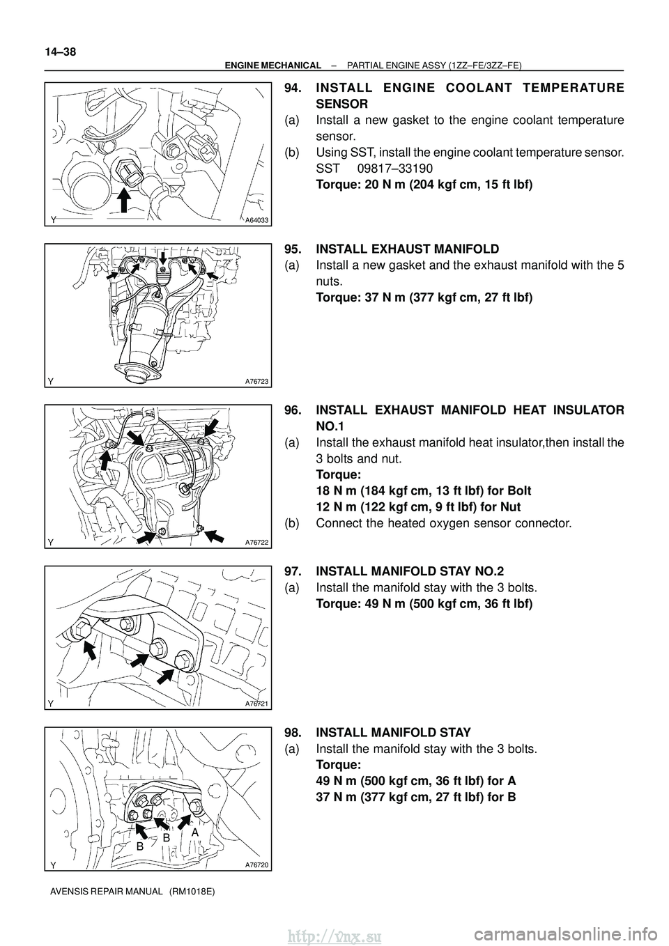
94. INSTALL ENGINE COOLANT TEMPERATURE SENSOR
(a) Install a new gasket to the engine coolant temperature
sensor.
(b) Using SST, install the engine coolant temperature sensor. SST 09817±33190
Torque: 20 N� m (204 kgf�cm, 15 ft�lbf)
95. INSTALL EXHAUST MANIFOLD
(a) Install a new gasket and the exhaust manifold with the 5 nuts.
Torque: 37 N �m (377 kgf� cm, 27 ft�lbf)
96. INSTALL EXHAUST MANIFOLD HEAT INSULATOR NO.1
(a) Install the exhaust manifold heat insulator,then install the 3 bolts and nut.
Torque:
18 N�m (184 kgf� cm, 13 ft�lbf) for Bolt
12 N� m (122 kgf� cm, 9 ft�lbf) for Nut
(b) Connect the heated oxygen sensor connector.
97. INSTALL MANIFOLD STAY NO.2
(a) Install the manifold stay with the 3 bolts. Torque: 49 N �m (500 kgf� cm, 36 ft�lbf)
98. INSTALL MANIFOLD STAY
(a) Install the manifold stay with the 3 bolts. Torque:
49 N�m (500 kgf� cm, 36 ft�lbf) for A
37 N� m (377 kgf� cm, 27 ft�lbf) for B
http://vnx.su
Page 698 of 2234
A62204
1
5
3
82
6
4
7
A76719
A76718
A76717
14±42
±
ENGINE MECHANICAL PARTIAL ENGINE ASSY (1ZZ±FE/3ZZ±FE)
AVENSIS REPAIR MANUAL (RM1018E)
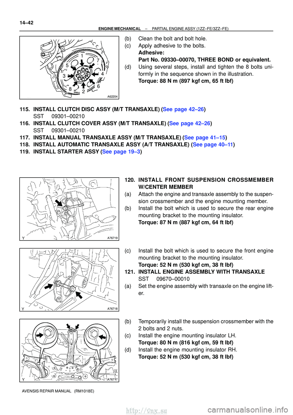
(b) Clean the bolt and bolt hole.
(c) Apply adhesive to the bolts. Adhesive:
Part No. 09330±00070, THREE BOND or equivalent.
(d) Using several steps, install and tighten the 8 bolts uni- formly in the sequence shown in the illustration.
Torque: 88 N �m (897 kgf� cm, 65 ft�lbf)
115.INSTALL CLUTCH DISC ASSY (M/T TRANSAXLE)(See page 42±26) SST 09301±00210
116.INSTALL CLUTCH COVER ASSY (M/T TRANSAXLE)(See page 42±26) SST 09301±00210
117.INSTALL MANUAL TRANSAXLE ASSY (M/T TRANSAXLE)(See page 41±15)
118.INSTALL AUTOMATIC TRANSAXLE ASSY (A/T TRANSAXLE) (See page 40±11)
119.INSTALL STARTER ASSY(See page 19±3)
120. INS TALL FRO NT SUSPENSION CROSSMEMBER
W/CENTER MEMBER
(a) Attach the engine and transaxle assembly to the suspen- sion crossmember and the engine mounting member.
(b) Install the bolt which is used to secure the rear engine
mounting bracket to the mounting insulator.
Torque: 87 N �m (887 kgf� cm, 64 ft�lbf)
(c) Install the bolt which is used to secure the front engine mounting bracket to the mounting insulator.
Torque: 52 N �m (530 kgf� cm, 38 ft�lbf)
121. INSTALL ENGINE ASSEMBLY WITH TRANSAXLE
SST 09670±00010
(a) Set the engine assembly with transaxle on the engine lift- er.
(b) Temporarily install the suspension crossmember with the 2 bolts and 2 nuts.
(c) Install the engine mounting insulator LH.
Torque: 80 N �m (816 kgf� cm, 59 ft�lbf)
(d) Install the engine mounting insulator RH. Torque: 52 N �m (530 kgf� cm, 38 ft�lbf)
http://vnx.su
Page 701 of 2234
141C5±01
A79425N´m (kgf´cm, ft´lbf): Specified torque
8.0 (82, 71 in.�lbf)
72 (734, 53)
V (Cooler
Compressor to
Crankshaft
Pulley) Belt No. 1
Engine Cover No. 1Engine Room Cover Side
Radiator Support
Opening Cover
Power Steering
Idle Pulley Bracket Engine Under Cover Sub±assy No. 1
Engine Under Cover RH
Injector Driver
52 (530, 38)
Engine Mounting Insulator Sub±assy RH
52 (530, 38)
52 (530, 38)
39 (398, 29)
Clip
Clip
Retainer
Clip
Clip
5.0 (51, 44 in. �lbf)
±
ENGINE MECHANICAL TIMING BELT (1CD±FTV)
14±305
AVENSIS REPAIR MANUAL (RM1018E)
TIMING BELT (1CD±FTV)
COMPONENTS
http://vnx.su
Page 703 of 2234
141C6±01
A61184
A79179
A61182
SST (B)
SSTSST (A)
±
ENGINE MECHANICALTIMING BELT(1CD±FTV)
14±307
AVENSIS REPAIR MANUAL (RM1018E)
REPLACEMENT
1.REMOVE FRONT WHEEL RH
2.REMOVE ENGINE UNDER COVER SUB±ASSY NO.1
3.REMOVE ENGINE UNDER COVER RH
4.REMOVE RADIATOR SUPPORT OPENING COVER
5.REMOVE ENGINE ROOM COVER SIDE
6.REMOVE ENGINE COVER NO.1
(a)Remove the 5 nuts and the engine cover.
7.REMOVE INJECTOR DRIVER (See page 14±286)
8.REMOVE V (COOLER COMPRESSOR TO CRANKSHAFT PULLEY) BELT NO.1
(See page 14±269)
9.REMOVE GENERATOR V BELT (See page 14±269)
10.SEPARATE POWER STEERING IDLE PULLEY BRACKET (See page 14±286)
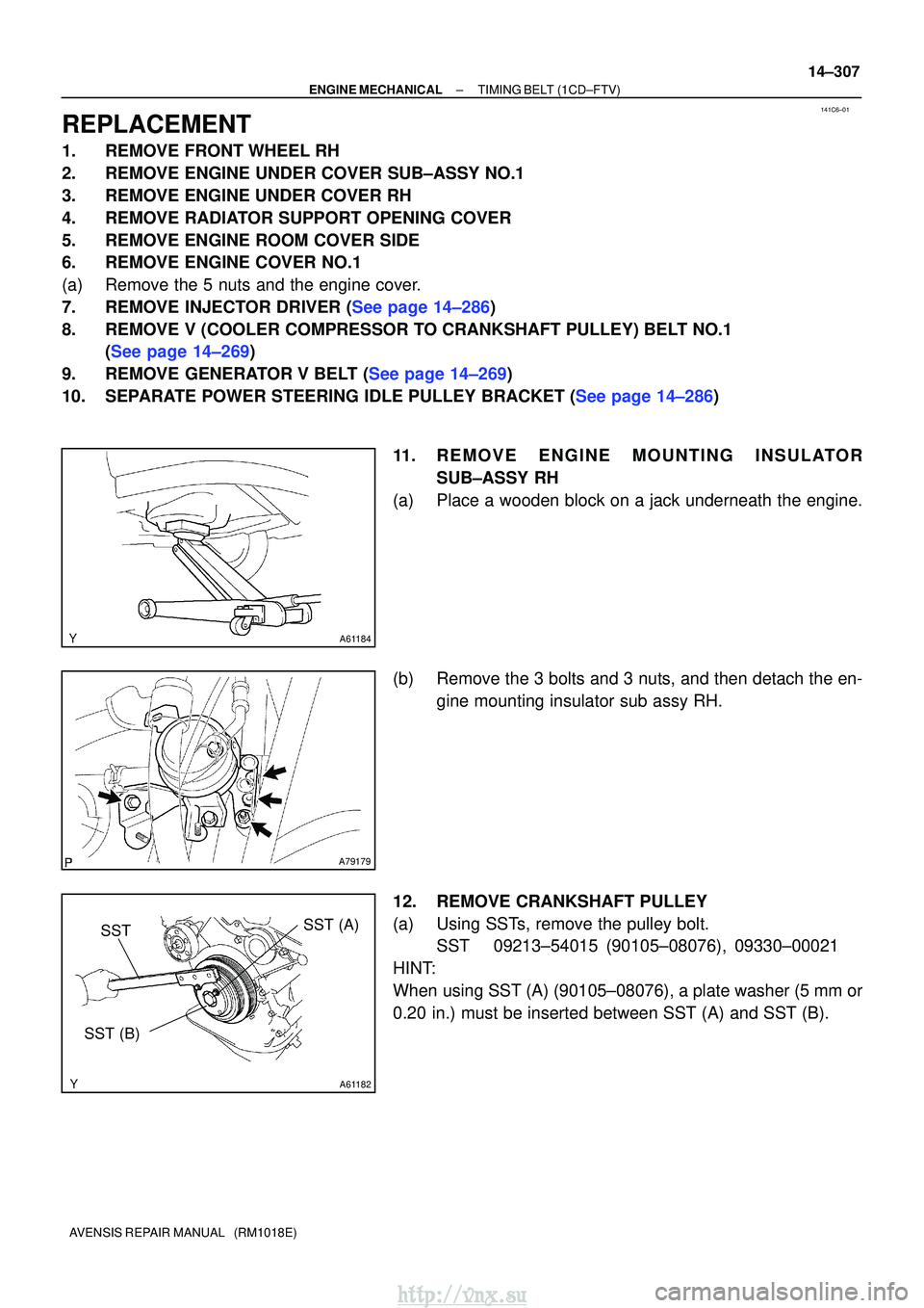
11. REMOVE ENGINE MOUNTING INSULATORSUB±ASSY RH
(a) Place a wooden block on a jack underneath the engine.
(b) Remove the 3 bolts and 3 nuts, and then detach the en- gine mounting insulator sub assy RH.
12. REMOVE CRANKSHAFT PULLEY
(a) Using SSTs, remove the pulley bolt. SST 09213±54015 (90105±08076), 09330±00021
HINT:
When using SST (A) (90105±08076), a plate washer (5 mm or
0.20 in.) must be inserted between SST (A) and SST (B).
http://vnx.su
Page 708 of 2234
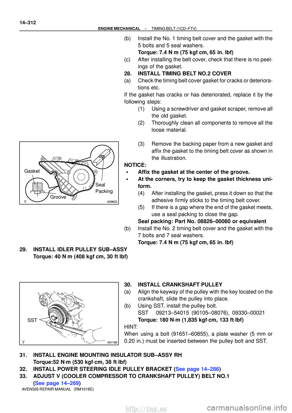
A09602
Seal
Packing
Gasket
Groove
A61186
SST
14±312
±
ENGINE MECHANICALTIMING BELT(1CD±FTV)
AVENSIS REPAIR MANUAL (RM1018E)
(b)Install the No. 1 timing belt cover and the gasket with the 5 bolts and 5 seal washers.
Torque: 7.4 N �m (75 kgf�cm,65 in. �lbf)
(c)After installing the belt cover, check that there is no peel- ings of the gasket.
28.INSTALL TIMING BELT NO.2 COVER
(a)Check the timing belt cover gasket for cracks or deteriora- tions etc.
If the gasket has cracks or has deteriorated, replace it by the
following steps: (1)Using a screwdriver and gasket scraper, remove allthe old gasket.
(2)Thoroughly clean all components to remove all the loose material.
(3)Remove the backing paper from a new gasket and affix the gasket to the timing belt cover as shown in
the illustration.
NOTICE:
�Affix the gasket at the center of the groove.
�At the corners, try to keep the gasket thickness uni-
form.
(4)After installing the gasket, press it down so that the adhesive firmly sticks to the timing belt cover.
(5)If there is a gap where the end of the gasket meets,
use a seal packing to close the gap.
Seal packing: Part No. 08826±00080 or equivalent
(b)Install the No. 2 timing belt cover and the gasket with the 7 bolts and 7 seal washers.
Torque: 7.4 N �m (75 kgf�cm,65 in. �lbf)
29.INSTALL IDLER PULLEY SUB±ASSY Torque: 40 N �m (408 kgf�cm, 30 ft�lbf)
30.INSTALL CRANKSHAFT PULLEY
(a)Align the keyway of the pulley with the key located on thecrankshaft, slide the pulley into place.
(b)Using SST, install the pulley bolt. SST09213±54015 (90105±08076), 09330±00021
Torque: 180 N´m (1,835 kgf´cm, 133 ft´lbf)
HINT:
When using a bolt (91651±60855), a plate washer (5 mm or
0.20 in.) must be inserted between the pulley bolt and SST.
31.INSTALL ENGINE MOUNTING INSULATOR SUB±ASSY RH Torque:52 N´m (530 kgf´cm, 38 ft´lbf)
32.INSTALL POWER STEERING IDLE PULLEY BRACKET (See page 14±286)
33. ADJUST V (COOLER COMPRESSOR TO CRANKSHAFT PULLEY) BELT NO.1 (See page 14±269)
http://vnx.su
Page 710 of 2234
141CN±01
A60622
A01045
A64005
A62837SST
14±96±
ENGINE MECHANICALTIMING CHAIN OR BELT COVER OIL
SEAL(1ZZ±FE/3ZZ±FE)
AVENSIS REPAIR MANUAL (RM1018E)
TIMING GEAR COVER OIL SEAL(1ZZ±FE/3ZZ±FE)
REPLACEMENT
1.REMOVE FRONT WHEEL RH (See page 14±27)
2.REMOVE ENGINE UNDER COVER SUB±ASSY NO.1 (See page 14±27)
3.REMOVE ENGINE UNDER COVER RH (See page 14±27)
4.REMOVE RADIATOR SUPPORT OPENING COVER (See page 14±27)
5.REMOVE ENGINE ROOM COVER SIDE (See page 14±27) 6. REMOVE FAN AND GENERATOR V BELT
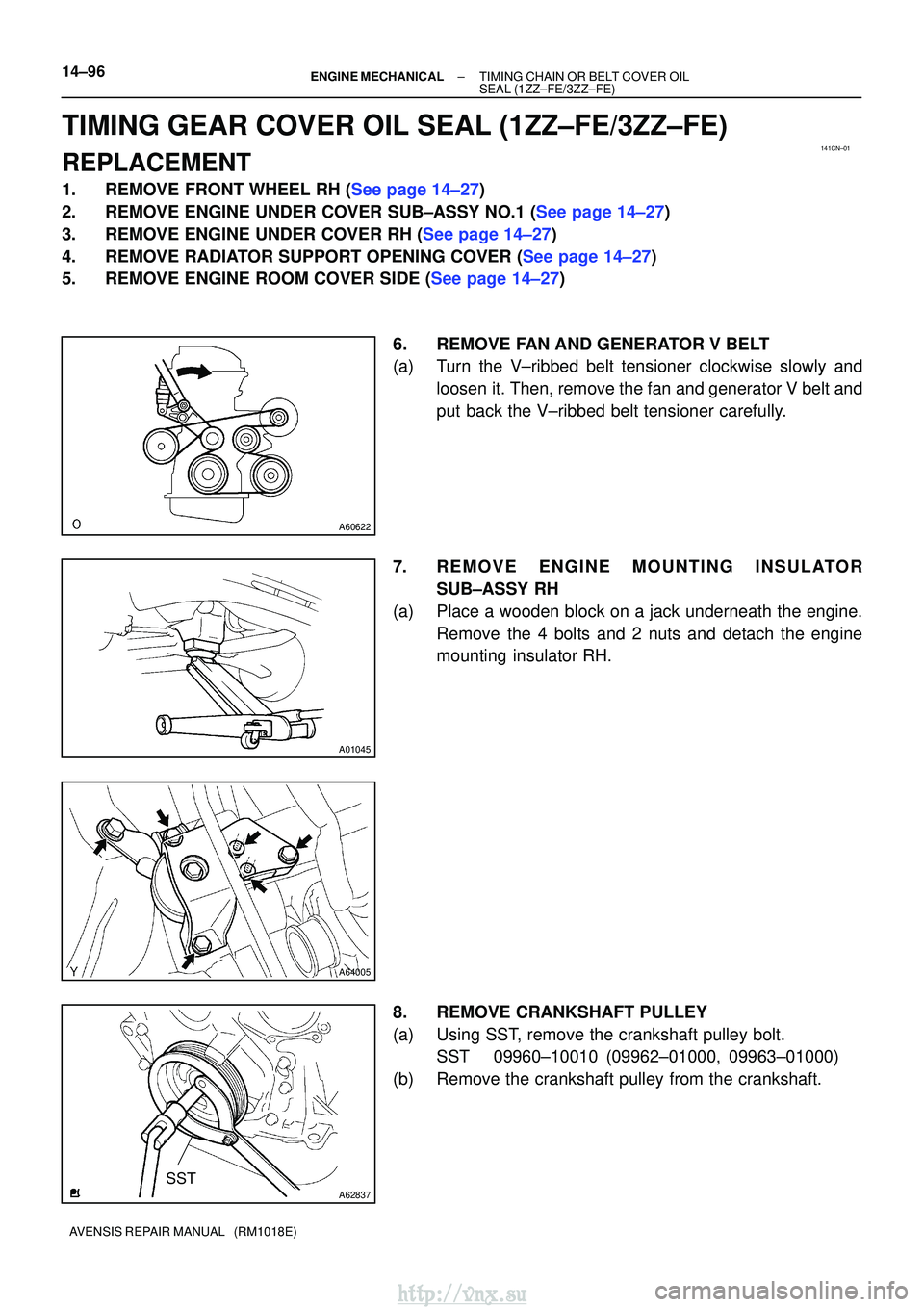
(a) Turn the V±ribbed belt tensioner clockwise slowly andloosen it. Then, remove the fan and generator V belt and
put back the V±ribbed belt tensioner carefully.
7. REMOVE ENGINE MOUNTING INSULATOR SUB±ASSY RH
(a) Place a wooden block on a jack underneath the engine. Remove the 4 bolts and 2 nuts and detach the engine
mounting insulator RH.
8. REMOVE CRANKSHAFT PULLEY
(a) Using SST, remove the crankshaft pulley bolt. SST 09960±10010 (09962±01000, 09963±01000)
(b) Remove the crankshaft pulley from the crankshaft.
http://vnx.su