Page 1187 of 2234
4105R±02
D30060
1ZZ±FE, 3ZZ±FE:
1AZ±FE, 1AZ±FSE, 1CD±FTV:
D30070
±
MANUAL TRANSMISSION/TRANSAXLE TRANSMISSION CONTROL CABLE ASSY (MTM)
41±7
AVENSIS REPAIR MANUAL (RM1018E)
TRANSMISSION CONTROL CABLE ASSY (MTM)
REPLACEMENT
HINT:
COMPONENTS: See page 41±10
1.REMOVE AIR CONDITIONER UNIT ASSY (See page 55±55)
HINT:
Refer to the instructions for removal of the instrument panel sub±ass\
y lower.
2. REMOVE EXHAUST PIPE ASSY
(a)1ZZ±FE, 3ZZ±FE Engine (See page 15±2)
(b)1AZ±FE, 1AZ±FSE Engine (See page 15±7)
(c)1CD±FTV Engine (See page 15±10)
3. REMOVE FRONT FLOOR HEAT INSULATOR NO.1 (GASOLINE ENGINE TYPE)
(a) Remove the 3 nuts and heat insulator No.1.
4. REMOVE TRANSMISSION CONTROL CABLE ASSY
(a) Remove the 2 clips, separate the 2 cables from the trans-axle.
(b) Remove the 2 clips, separate the 2 cables from the brack- et.
(c) Remove the 2 nuts, separate the control cable assy.
http://vnx.su
Page 1189 of 2234

D26894
Serrate Part
D30070
D30060
1ZZ±FE, 3ZZ±FE:
1AZ±FE, 1AZ±FSE, 1CD±FTV:
±
MANUAL TRANSMISSION/TRANSAXLE TRANSMISSION CONTROL CABLE ASSY (MTM)
41±9
AVENSIS REPAIR MANUAL (RM1018E)
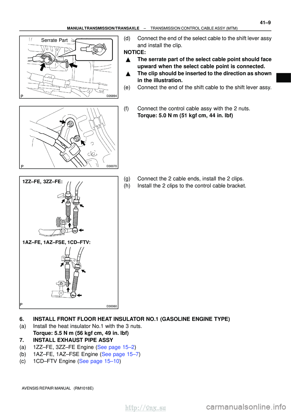
(d) Connect the end of the select cable to the shift lever assy
and install the clip.
NOTICE:
�The serrate part of the select cable point should face
upward when the select cable point is connected.
�The clip should be inserted to the direction as shown
in the illustration.
(e) Connect the end of the shift cable to the shift lever assy.
(f) Connect the control cable assy with the 2 nuts. Torque: 5.0 N �m (51 kgf �cm, 44 in. �lbf)
(g) Connect the 2 cable ends, install the 2 clips.
(h) Install the 2 clips to the control cable bracket.
6. INSTALL FRONT FLOOR HEAT INSULATOR NO.1 (GASOLINE ENGINE TYPE)
(a) Install the heat insulator No.1 with the 3 nuts. Torque: 5.5 N �m (56 kgf �cm, 49 in. �lbf)
7. INSTALL EXHAUST PIPE ASSY
(a)1ZZ±FE, 3ZZ±FE Engine (See page 15±2)
(b)1AZ±FE, 1AZ±FSE Engine (See page 15±7)
(c)1CD±FTV Engine (See page 15±10)
http://vnx.su
Page 1252 of 2234

�����\b�����D30389
AZ Series:1CD±FTV:
No.1 Engine Hanger
No.2 Engine Hanger
No.1 Engine Hanger
No.2 Engine Hanger
No.1 Engine
Hanger UPR
D29969
C94595
51±38
±
POWER STEERING RACK & PINION POWER STEERING GEAR ASSY
AVENSIS REPAIR MANUAL (RM1018E)
15.SEPARATE FRONT SUSPENSION ARM SUB±ASSY LOWER NO.1 LH (See page 30±6)
16. SEPARATE FRONT SUSPENSION ARM SUB±ASSY LOWER NO.1 RH
HINT:
Perform the same procedure on the other side.
17. REMOVE HOOD SUB±ASSY
18. REMOVE CYLINDER HEAD COVER SUB±ASSY 19. SUSPEND ENGINE ASSEMBLY
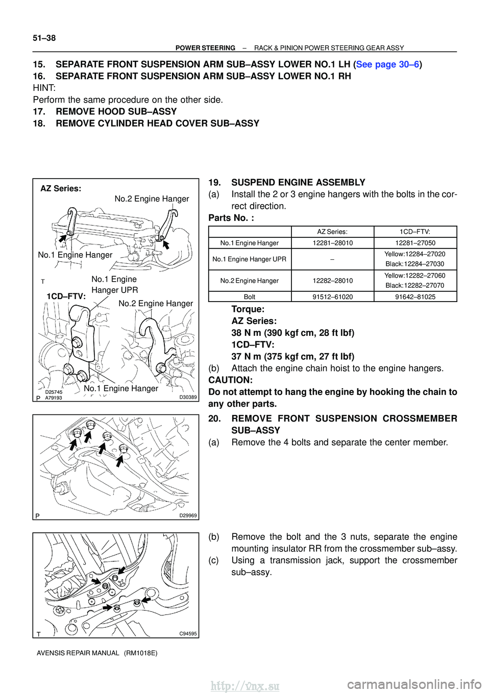
(a) Install the 2 or 3 engine hangers with the bolts in the cor-rect direction.
Parts No. :
AZ Series:1CD±FTV:
No.1 Engine Hanger12281±2801012281±27050
No.1 Engine Hanger UPR±Yellow: 12284±27020
Black: 12284±27030
No.2 Engine Hanger12282±28010Yellow: 12282±27060Black: 12282±27070
Bolt91512±6102091642±81025
Torque:
AZ Series:
38 N� m (390 kgf� cm, 28 ft�lbf)
1CD±FTV:
37 N� m (375 kgf� cm, 27 ft�lbf)
(b) Attach the engine chain hoist to the engine hangers.
CAUTION:
Do not attempt to hang the engine by hooking the chain to
any other parts.
20. REMOVE FRONT SUSPENSION CROSSMEMBER
SUB±ASSY
(a) Remove the 4 bolts and separate the center member.
(b) Remove the bolt and the 3 nuts, separate the engine mounting insulator RR from the crossmember sub±assy.
(c) Using a transmission jack, support the crossmember
sub±assy.
http://vnx.su
Page 1257 of 2234

C94598
C94596
A
BB
B
LH:
C94597
A
BB
B
RH:
C94595
D29969
A
B
A
B
±
POWER STEERING RACK & PINION POWER STEERING GEAR ASSY
51±43
AVENSIS REPAIR MANUAL (RM1018E)
43. INSTALL FRONT SUSPENSION CROSSMEMBER
SUB±ASSY
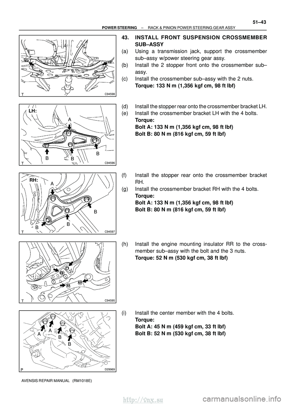
(a) Using a transmission jack, support the crossmember
sub±assy w/power steering gear assy.
(b) Install the 2 stopper front onto the crossmember sub± assy.
(c) Install the crossmember sub±assy with the 2 nuts.
Torque: 133 N� m (1,356 kgf�cm, 98 ft �lbf)
(d) Install the stopper rear onto the crossmember bracket LH.
(e) Install the crossmember bracket LH with the 4 bolts. Torque:
Bolt A: 133 N� m (1,356 kgf�cm, 98 ft �lbf)
Bolt B: 80 N� m (816 kgf�cm, 59 ft�lbf)
(f) Install the stopper rear onto the crossmember bracket RH.
(g) Install the crossmember bracket RH with the 4 bolts. Torque:
Bolt A: 133 N� m (1,356 kgf�cm, 98 ft �lbf)
Bolt B: 80 N� m (816 kgf�cm, 59 ft�lbf)
(h) Install the engine mounting insulator RR to the cross- member sub±assy with the bolt and the 3 nuts.
Torque: 52 N �m (530 kgf� cm, 38 ft�lbf)
(i) Install the center member with the 4 bolts. Torque:
Bolt A: 45 N� m (459 kgf�cm, 33 ft�lbf)
Bolt B: 52 N� m (530 kgf�cm, 38 ft�lbf)
http://vnx.su
Page 1780 of 2234
750MT±01
B67533
Hood Sub±assyHood Insulator
Engine Room Side Cover RH
Radiator CoverBattery Service Hole Cover
Hood Hinge Assy RH
Hood to Front Fender Seal RH
Hood Lock Assy
Front Bumper Assy
Hood to Front Fender Seal LH
Hood Hinge Assy LH x 8
Hood to Front End Panel Seal
8.0 (82, 71 in.´lbf)
13 (133, 10)
13 (133, 10)
: Specified torqueN´m (kgf´cm, ft´lbf) Cushion Rubber
Cushion Rubber
Clip
±
ENGINE HOOD/DOOR HOOD
75±1
AVENSIS REPAIR MANUAL (RM1018E)
HOOD
COMPONENTS
http://vnx.su