Page 711 of 2234
A62183
Cut Position
Pry
A62184
SST
A62837SST
A64005
±
ENGINE MECHANICAL TIMING CHAIN OR BELT COVER OIL
SEAL (1ZZ±FE/3ZZ±FE)14±97
AVENSIS REPAIR MANUAL (RM1018E)
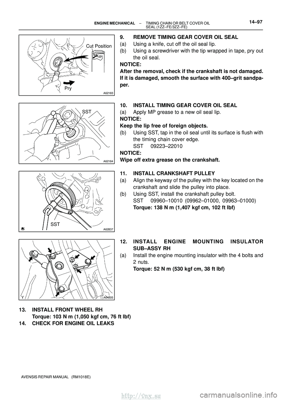
9. REMOVE TIMING GEAR COVER OIL SEAL
(a) Using a knife, cut off the oil seal lip.
(b) Using a screwdriver with the tip wrapped in tape, pry out
the oil seal.
NOTICE:
After the removal, check if the crankshaft is not damaged.
If it is damaged, smooth the surface with 400±grit sandpa-
per.
10. INSTALL TIMING GEAR COVER OIL SEAL
(a) Apply MP grease to a new oil seal lip.
NOTICE:
Keep the lip free of foreign objects.
(b) Using SST, tap in the oil seal until its surface is flush with the timing chain cover edge.
SST 09223±22010
NOTICE:
Wipe off extra grease on the crankshaft.
11. INSTALL CRANKSHAFT PULLEY
(a) Align the keyway of the pulley with the key located on the crankshaft and slide the pulley into place.
(b) Using SST, install the crankshaft pulley bolt. SST 09960±10010 (09962±01000, 09963±01000)
Torque: 138 N� m (1,407 kgf�cm, 102 ft� lbf)
12. INSTALL ENGINE MOUNTING INSULATOR SUB±ASSY RH
(a) Install the engine mounting insulator with the 4 bolts and 2 nuts.
Torque: 52 N �m (530 kgf� cm, 38 ft�lbf)
13. INSTALL FRONT WHEEL RH Torque: 103 N� m (1,050 kgf�cm, 76 ft �lbf)
14. CHECK FOR ENGINE OIL LEAKS
http://vnx.su
Page 723 of 2234
A01132
A60622
A01045
A64005
14±8
±
ENGINE MECHANICAL VALVE CLEARANCE (1ZZ±FE/3ZZ±FE)
AVENSIS REPAIR MANUAL (RM1018E)
(b) Turn the crankshaft 1 revolution (360 �) and set No. 4 cyl-
inder to TDC/compression.
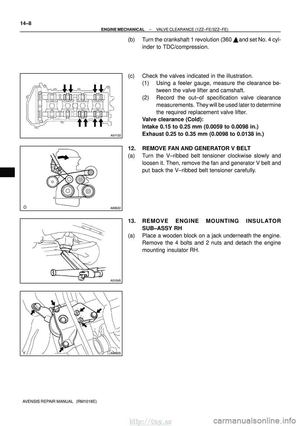
(c) Check the valves indicated in the illustration. (1) Using a feeler gauge, measure the clearance be-
tween the valve lifter and camshaft.
(2) Record the out±of specification valve clearance measurements. They will be used later to determine
the required replacement valve lifter.
Valve clearance (Cold):
Intake 0.15 to 0.25 mm (0.0059 to 0.0098 in.)
Exhaust 0.25 to 0.35 mm (0.0098 to 0.0138 in.)
12. REMOVE FAN AND GENERATOR V BELT
(a) Turn the V±ribbed belt tensioner clockwise slowly and loosen it. Then, remove the fan and generator V belt and
put back the V±ribbed belt tensioner carefully.
13. REMOVE ENGINE MOUNTING INSULATOR SUB±ASSY RH
(a) Place a wooden block on a jack underneath the engine. Remove the 4 bolts and 2 nuts and detach the engine
mounting insulator RH.
http://vnx.su
Page 731 of 2234
A62180
DisconnectHook
Pin Turn
A62181
Plunger
Turn
Push
A11858
A64005
14±16
±
ENGINE MECHANICAL VALVE CLEARANCE (1ZZ±FE/3ZZ±FE)
AVENSIS REPAIR MANUAL (RM1018E)
(3) Turn the crankshaft counterclockwise, and take the hook off the knock pin to release the plunger.
(4) Turn the crankshaft clockwise, and check that the plunger is extended.
HINT:
If the plunger does not be extended, press the slipper into the
chain tensioner using a screwdriver so that the hook is took off
from the knock pin and let the plunger can be extended.
16. INSTALL V±RIBBED BELT TENSIONER ASSY
(a) Install the V±ribbed belt tensioner with the nut and bolt. Torque:
29 N�m (296 kgf� cm, 21 ft�lbf) for Nut
69 N� m (704 kgf� cm, 51 ft�lbf) for Bolt
17. INSTALL ENGINE MOUNTING INSULATOR SUB±ASSY RH
(a) Install the engine mounting insulator with the 4 bolts and 2 nuts.
Torque: 52 N �m (530 kgf� cm, 38 ft�lbf)
http://vnx.su
Page 838 of 2234
0300R±02
±
SERVICE SPECIFICATIONS STARTING & CHARGING
03±11
1ZZ±FE,3ZZ±FE ENGINE REPAIR MANUAL
(RM923E)
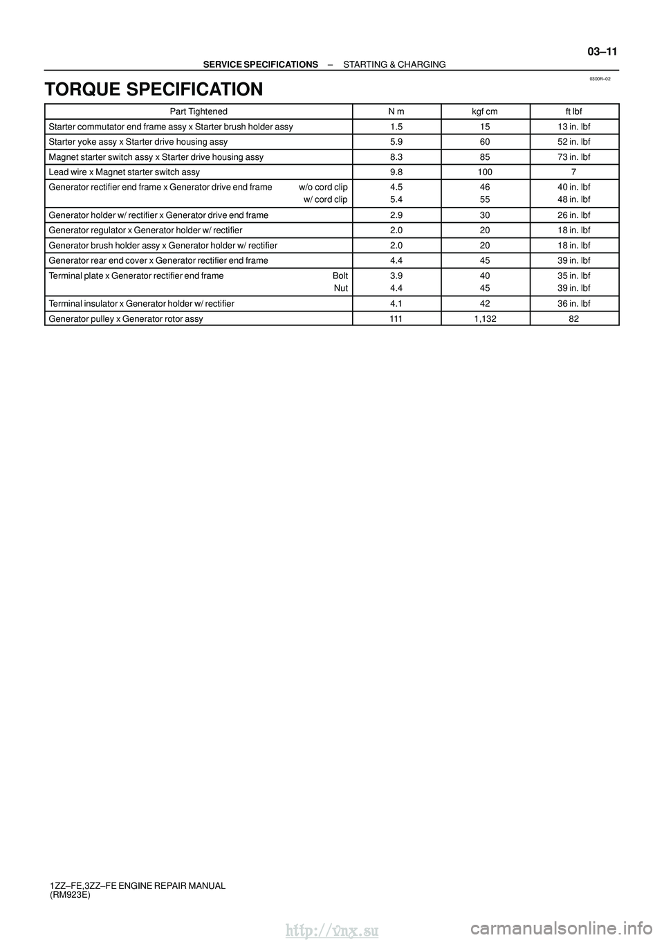
TORQUE SPECIFICATION
Part TightenedN�mkgf �cmft �lbf
Starter commutator end frame assy x Starter brush holder assy1.51513 in.� lbf
Starter yoke assy x Starter drive housing assy5.96052 in.�lbf
Magnet starter switch assy x Starter drive housing assy8.38573 in.�lbf
Lead wire x Magnet starter switch assy9.81007
Generator rectifier end frame x Generator drive end frame w/o cord clip
w/ cord clip4.5
5.446
5540 in.�lbf
48 in.� lbf
Generator holder w/ rectifier x Generator drive end frame2.93026 in.�lbf
Generator regulator x Generator holder w/ rectifier2.02018 in.�lbf
Generator brush holder assy x Generator holder w/ rectifier2.02018 in.�lbf
Generator rear end cover x Generator rectifier end frame4.44539 in.�lbf
Terminal plate x Generator rectifier end frame Bolt
Nut3.9
4.440
4535 in.� lbf
39 in.� lbf
Terminal insulator x Generator holder w/ rectifier4.14236 in.�lbf
Generator pulley x Generator rotor assy1111,13282
http://vnx.su
Page 840 of 2234
190A9±01
A62217
Generator PulleyGenerator Drive End Frame
Terminal Insulator
Generator Rotor Assy Washer
Generator Rectifier End Frame Generator
Cord Clip
Generator Plate SealGenerator Holder W/ Rectifier
Generator Regulator
Generator Brush Holder Assy Generator Brush Cover
Terminal Plate
Terminal Insulator
111 (1,132, 82)
2.9 (30, 26 in.�lbf)
4.4 (45, 39 in. �lbf)
3.9 (40, 35 in. �lbf)
2.0 (20, 18 in. �lbf)
2.0 (20, 18 in. �lbf)
4.5 (46, 40 in. �lbf) W/O Cord Clip
5.4 (55, 48in.� lbf) W/ Cord Clip
4.1 (42, 36 in. �lbf)
Generator Rear End Cover
N´m (kgf´cm, ft´lbf)
: Specified torque
±
STARTING & CHARGING GENERATOR ASSY (1ZZ±FE/3ZZ±FE)
19±9
1ZZ±FE,3ZZ±FE ENGINE REPAIR MANUAL
(RM923E)
GENERATOR ASSY (1ZZ±FE/3ZZ±FE)
COMPONENTS
http://vnx.su
Page 842 of 2234
A62757
SST
A62881
FB
A62882
E F
±
STARTING & CHARGING GENERATOR ASSY (1ZZ±FE/3ZZ±FE)
19±11
1ZZ±FE,3ZZ±FE ENGINE REPAIR MANUAL
(RM923E)
2. REMOVE GENERATOR BRUSH HOLDER ASSY
(a) Remove the nut and terminal insulator.
(b) Remove the screw, nut and terminal plate.
(c) Remove the 2 nuts and rear end cover.
(d) Remove the brush cover from the brush holder.
(e) Remove the 2 screw and brush holder.
3. REMOVE GENERATOR REGULATOR ASSY
(a) Remove the 3 screws and regulator.
4. REMOVE GENERATOR HOLDER W/RECTIFIER
(a) Remove the 4 screws and holder w/ rectifier.
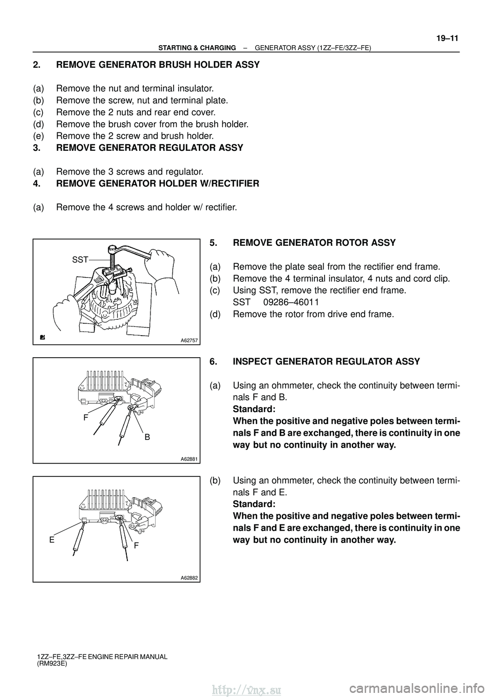
5. REMOVE GENERATOR ROTOR ASSY
(a) Remove the plate seal from the rectifier end frame.
(b) Remove the 4 terminal insulator, 4 nuts and cord clip.
(c) Using SST, remove the rectifier end frame.SST 09286±46011
(d) Remove the rotor from drive end frame.
6. INSPECT GENERATOR REGULATOR ASSY
(a) Using an ohmmeter, check the continuity between termi- nals F and B.
Standard:
When the positive and negative poles between termi-
nals F and B are exchanged, there is continuity in one
way but no continuity in another way.
(b) Using an ohmmeter, check the continuity between termi- nals F and E.
Standard:
When the positive and negative poles between termi-
nals F and E are exchanged, there is continuity in one
way but no continuity in another way.
http://vnx.su
Page 845 of 2234
A62753
SST
1 ± BSST
1 ± A
A62754SST 2
A62765
SST
1 ± A
19±14
±
STARTING & CHARGING GENERATOR ASSY (1ZZ±FE/3ZZ±FE)
1ZZ±FE,3ZZ±FE ENGINE REPAIR MANUAL
(RM923E)
(b) Install the rear end cover with the 2 nuts. Torque: 4.4 N �m (45 kgf �cm, 39 in. �lbf)
(c) Install the terminal plate with the screw and nut.
Torque:
Bolt 3.9 N �m (40 kgf �cm, 35 in. �lbf)
Nut 4.4 N� m (45 kgf�cm, 39 in. �lbf)
(d) Install the terminal insulator withe the nut.
Torque: 4.1 N �m (42 kgf �cm, 36 in. �lbf)
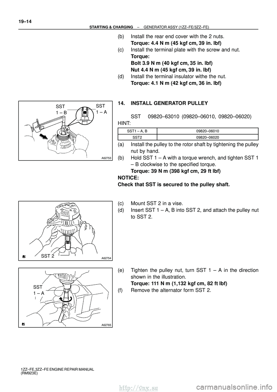
14. INSTALL GENERATOR PULLEY SST 09820±63010 (09820±06010, 09820±06020)
HINT:
SST1 ± A, B09820±06010
SST209820±06020
(a) Install the pulley to the rotor shaft by tightening the pulley nut by hand.
(b) Hold SST 1 ± A with a torque wrench, and tighten SST 1 ± B clockwise to the specified torque.
Torque: 39 N �m (398 kgf� cm, 29 ft�lbf)
NOTICE:
Check that SST is secured to the pulley shaft.
(c) Mount SST 2 in a vise.
(d) Insert SST 1 ± A, B into SST 2, and attach the pulley nut to SST 2.
(e) Tighten the pulley nut, turn SST 1 ± A in the direction shown in the illustration.
Torque: 111 N� m (1,132 kgf�cm, 82 ft �lbf)
(f) Remove the alternator form SST 2.
http://vnx.su
Page 903 of 2234
160ME±01
A79148
SST
16±46
±
COOLINGWATER PUMP ASSY(1CD±FTV)
AVENSIS REPAIR MANUAL (RM1018E)
WATER PUMP ASSY(1CD±FTV)
REPLACEMENT
1.REMOVE RADIATOR SUPPORT OPENING COVER
2.REMOVE ENGINE ROOM COVER SIDE
3.DRAIN ENGINE COOLANT(See page 16±44)
4.REMOVE FRONT WHEEL RH
5.REMOVE ENGINE UNDER COVER SUB±ASSY NO.1
6.REMOVE ENGINE UNDER COVER RH
7.REMOVE ENGINE COVER NO.1
(a)Remove the 5 nuts and the engine cover.
8.REMOVE INJECTOR DRIVER (See page 14±286)
9.REMOVE V (COOLER COMPRESSOR TO CRANKSHAFT PULLEY) BELT NO.1 (See page 14±269)
10.REMOVE GENERATOR V BELT (See page 14±269)
11.SEPARATE POWER STEERING IDLE PULLEY BRACKET (See page 14±286)
12.SEPARATE ENGINE MOUNTING INSULATOR SUB±ASSY RH(See page 14±307)
13.REMOVE CRANKSHAFT PULLEY(See page 14±307) SST 09213±54015 (90105±08076), 09330±00021, 09950±50013 (0995\
1±05010, 09952±05010, 09953±05020, 09954±05031)
14. REMOVE IDLER PULLEY SUB±ASSY
(a) Remove the bolt, the washer and the pulley.
15.REMOVE TIMING BELT NO.2 COVER(See page 14±307)
16.REMOVE TIMING BELT NO.1 COVER(See page 14±307)
17. REMOVE TIMING BELT GUIDE
18.REMOVE TRANSVERSE ENGINE ENGINE MOUNTING BRACKET(See page 14±307)
19.SET NO. 1 CYLINDER TO TDC/COMPRESSION(See page 14±307)
20.REMOVE TIMING CHAIN COVER PLATE(See page 14±307)
21.REMOVE TIMING BELT(See page 14±307)
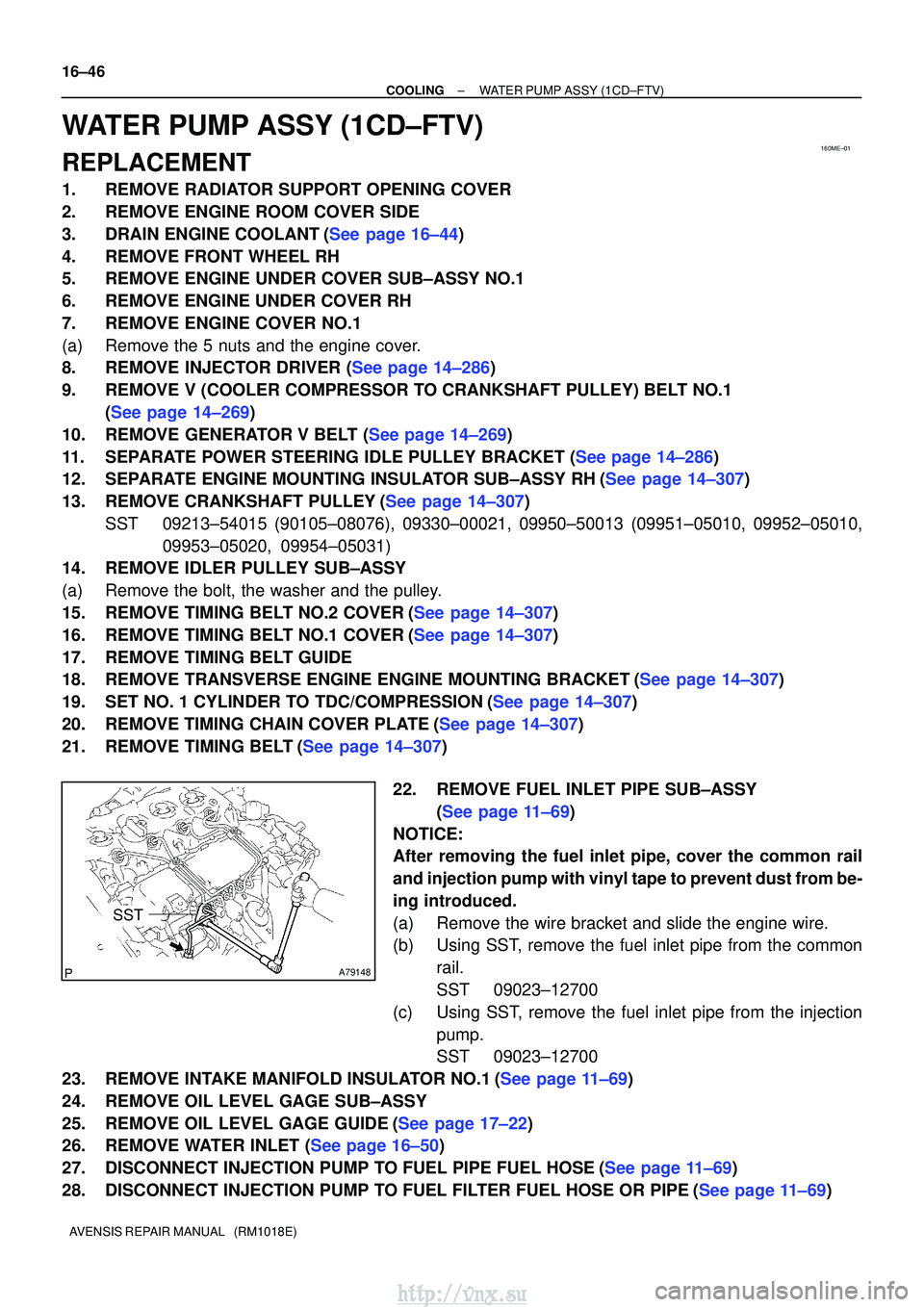
22. REMOVE FUEL INLET PIPE SUB±ASSY(See page 11±69)
NOTICE:
After removing the fuel inlet pipe, cover the common rail
and injection pump with vinyl tape to prevent dust from be-
ing introduced.
(a) Remove the wire bracket and slide the engine wire.
(b) Using SST, remove the fuel inlet pipe from the common rail.
SST 09023±12700
(c) Using SST, remove the fuel inlet pipe from the injection pump.
SST 09023±12700
23.REMOVE INTAKE MANIFOLD INSULATOR NO.1(See page 11±69)
24. REMOVE OIL LEVEL GAGE SUB±ASSY
25.REMOVE OIL LEVEL GAGE GUIDE(See page 17±22)
26.REMOVE WATER INLET (See page 16±50)
27.DISCONNECT INJECTION PUMP TO FUEL PIPE FUEL HOSE(See page 11±69)
28.DISCONNECT INJECTION PUMP TO FUEL FILTER FUEL HOSE OR PIPE(See page 11±69)
http://vnx.su