Page 664 of 2234
A79150
A61175
A09671
14±294
±
ENGINE MECHANICALPARTIAL ENGINE ASSY(1CD±FTV)
AVENSIS REPAIR MANUAL (RM1018E)
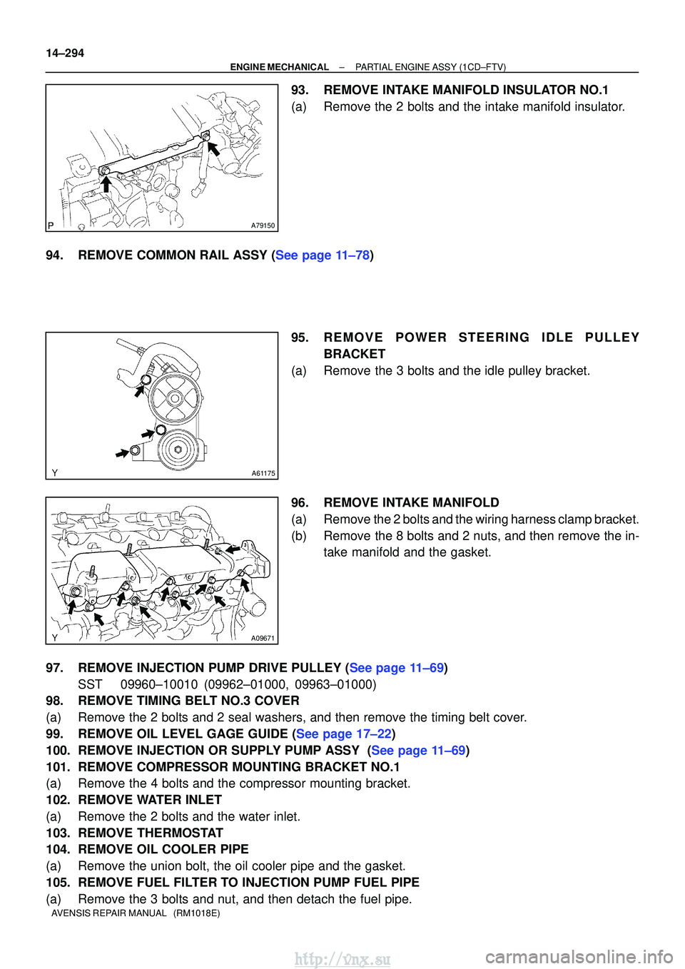
93.REMOVE INTAKE MANIFOLD INSULATOR NO.1
(a)Remove the 2 bolts and the intake manifold insulator.
94.REMOVE COMMON RAIL ASSY (See page 11±78) 95.REMOVE POWER STEERING IDLE PULLEY
BRACKET
(a)Remove the 3 bolts and the idle pulley bracket.
96.REMOVE INTAKE MANIFOLD
(a)Remove the 2 bolts and the wiring harness clamp bracket.
(b)Remove the 8 bolts and 2 nuts, and then remove the in- take manifold and the gasket.
97.REMOVE INJECTION PUMP DRIVE PULLEY (See page 11±69) SST 09960±10010 (09962±01000, 09963±01000)
98. REMOVE TIMING BELT NO.3 COVER
(a) Remove the 2 bolts and 2 seal washers, and then remove the timing belt c\
over.
99.REMOVE OIL LEVEL GAGE GUIDE (See page 17±22)
100.REMOVE INJECTION OR SUPPLY PUMP ASSY (See page 11±69)
101. REMOVE COMPRESSOR MOUNTING BRACKET NO.1
(a) Remove the 4 bolts and the compressor mounting bracket.
102. REMOVE WATER INLET
(a) Remove the 2 bolts and the water inlet.
103. REMOVE THERMOSTAT
104. REMOVE OIL COOLER PIPE
(a) Remove the union bolt, the oil cooler pipe and the gasket.
105. REMOVE FUEL FILTER TO INJECTION PUMP FUEL PIPE
(a) Remove the 3 bolts and nut, and then detach the fuel pipe.
http://vnx.su
Page 666 of 2234
A61175
AA
B
A79147
Fulcrum
Length
30 cm
SST
14±296
±
ENGINE MECHANICALPARTIAL ENGINE ASSY(1CD±FTV)
AVENSIS REPAIR MANUAL (RM1018E)
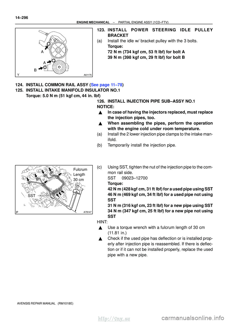
123.INSTALL POWER STEERING IDLE PULLEY BRACKET
(a)Install the idle w/ bracket pulley with the 3 bolts.
Torque:
72 N�m (734 kgf�cm, 53 ft�lbf) for bolt A
39 N�m (398 kgf�cm, 29 ft�lbf) for bolt B
124.INSTALL COMMON RAIL ASSY (See page 11±78)
125. INSTALL INTAKE MANIFOLD INSULATOR NO.1 Torque: 5.0 N �m (51 kgf �cm, 44 in. �lbf)
126. INSTALL INJECTION PIPE SUB±ASSY NO.1
NOTICE:
�In case of having the injectors replaced, must replace
the injection pipes, too.
�When assembling the pipes, perform the operation
with the engine cold under room temperature.
(a) Install the 2 lower injection pipe clamps to the intake man-
ifold.
(b) Temporarily install the injection pipe.
(c) Using SST, tighten the nut of the injection pipe to the com- mon rail side.
SST 09023±12700
Torque:
42 N�m (428 kgf� cm, 31 ft�lbf) for a used pipe using SST
46 N� m (469 kgf� cm, 34 ft�lbf) for a used pipe not using
SST
31 N �m (316 kgf� cm, 23 ft�lbf) for a new pipe using SST
34 N� m (347 kgf �cm, 25 ft �lbf) for a new pipe not using
SST
HINT:
�Use a torque wrench with a fulcrum length of 30 cm
(11.81 in.)
�Check if the used pipe has deflection or is installed prop-
erly after injection pipe is reassembled. If there is deflec-
tion or if it can not be installed properly, replace the used
pipe with a new pipe.
http://vnx.su
Page 669 of 2234
A79196
New O±Ring
New O±Ring
A79182
Collar
Groove
±
ENGINE MECHANICALPARTIAL ENGINE ASSY(1CD±FTV)
14±299
AVENSIS REPAIR MANUAL (RM1018E)
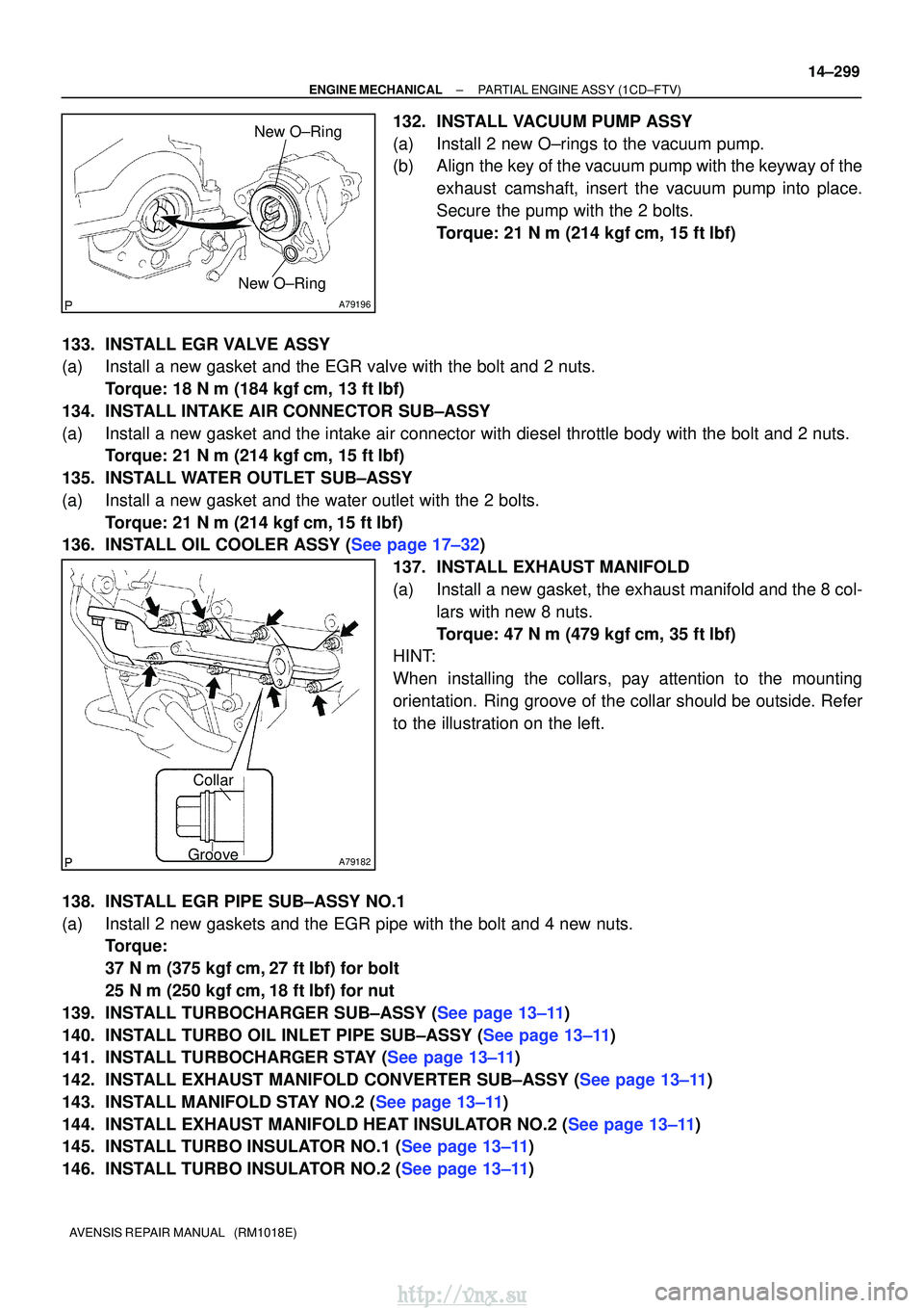
132.INSTALL VACUUM PUMP ASSY
(a)Install 2 new O±rings to the vacuum pump.
(b)Align the key of the vacuum pump with the keyway of the
exhaust camshaft, insert the vacuum pump into place.
Secure the pump with the 2 bolts.
Torque: 21 N �m (214 kgf�cm, 15 ft�lbf)
133.INSTALL EGR VALVE ASSY
(a)Install a new gasket and the EGR valve with the bolt and 2 nuts. Torque: 18 N �m (184 kgf�cm, 13 ft�lbf)
134.INSTALL INTAKE AIR CONNECTOR SUB±ASSY
(a)Install a new gasket and the intake air connector with diesel throttle b\
ody with the bolt and 2 nuts. Torque: 21 N �m (214 kgf�cm, 15 ft�lbf)
135.INSTALL WATER OUTLET SUB±ASSY
(a)Install a new gasket and the water outlet with the 2 bolts. Torque: 21 N �m (214 kgf�cm,15 ft�lbf)
136.INSTALL OIL COOLER ASSY (See page 17±32)
137.INSTALL EXHAUST MANIFOLD
(a)Install a new gasket, the exhaust manifold and the 8 col-lars with new 8 nuts.
Torque: 47 N �m (479 kgf�cm, 35 ft�lbf)
HINT:
When installing the collars, pay attention to the mounting
orientation. Ring groove of the collar should be outside. Refer
to the illustration on the left.
138.INSTALL EGR PIPE SUB±ASSY NO.1
(a)Install 2 new gaskets and the EGR pipe with the bolt and 4 new nuts. Torque:
37 N�m (375 kgf�cm,27 ft�lbf) for bolt
25 N�m (250 kgf�cm,18 ft�lbf) for nut
139.INSTALL TURBOCHARGER SUB±ASSY (See page 13±11)
140.INSTALL TURBO OIL INLET PIPE SUB±ASSY (See page 13±11)
141.INSTALL TURBOCHARGER STAY (See page 13±11)
142.INSTALL EXHAUST MANIFOLD CONVERTER SUB±ASSY (See page 13±11)
143.INSTALL MANIFOLD STAY NO.2 (See page 13±11)
144.INSTALL EXHAUST MANIFOLD HEAT INSULATOR NO.2 (See page 13±11)
145.INSTALL TURBO INSULATOR NO.1 (See page 13±11)
146.INSTALL TURBO INSULATOR NO.2 (See page 13±11)
http://vnx.su
Page 671 of 2234
A79183
2
1
3
4
5
6
7
8
A79180
A62711
A59792
±
ENGINE MECHANICALPARTIAL ENGINE ASSY(1CD±FTV)
14±301
AVENSIS REPAIR MANUAL (RM1018E)
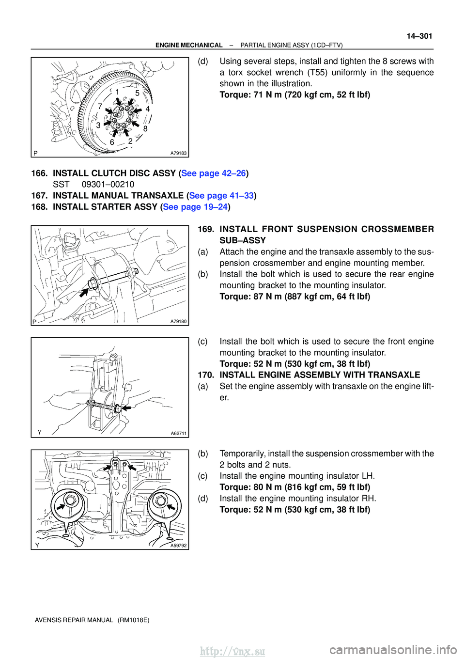
(d)Using several steps, install and tighten the 8 screws with
a torx socket wrench (T55) uniformly in the sequence
shown in the illustration.
Torque: 71 N �m (720 kgf�cm, 52 ft�lbf)
166.INSTALL CLUTCH DISC ASSY (See page 42±26) SST 09301±00210
167.INSTALL MANUAL TRANSAXLE (See page 41±33)
168.INSTALL STARTER ASSY (See page 19±24)
169. INS TALL FRO NT SUSPENSION CROSSMEMBER
SUB±ASSY
(a) Attach the engine and the transaxle assembly to the sus- pension crossmember and engine mounting member.
(b) Install the bolt which is used to secure the rear engine
mounting bracket to the mounting insulator.
Torque: 87 N �m (887 kgf� cm, 64 ft�lbf)
(c) Install the bolt which is used to secure the front engine mounting bracket to the mounting insulator.
Torque: 52 N �m (530 kgf� cm, 38 ft�lbf)
170. INSTALL ENGINE ASSEMBLY WITH TRANSAXLE
(a) Set the engine assembly with transaxle on the engine lift-
er.
(b) Temporarily, install the suspension crossmember with the 2 bolts and 2 nuts.
(c) Install the engine mounting insulator LH.
Torque: 80 N �m (816 kgf� cm, 59 ft�lbf)
(d) Install the engine mounting insulator RH. Torque: 52 N �m (530 kgf� cm, 38 ft�lbf)
http://vnx.su
Page 679 of 2234
A76705N´m (kgf´cm, ft´lbf) : Specified torque
Engine Mounting
Insulator RH
Engine Assembly with Transaxle
Front Suspension
Crossmember
W/ Center Member
80 (816, 59)
133 (1,356, 98)45 (459, 33)
52 (530, 38)
52 (530, 38)
87 (887, 64)
52 (530, 38)
Front Suspension
Member Brace RH
133 (1,356, 98)
80 (816, 59)
Front Suspension
Member Brace RH
133 (1,356, 98)
80 (816, 59)
X3X3
±
ENGINE MECHANICAL PARTIAL ENGINE ASSY (1ZZ±FE/3ZZ±FE)
14±23
AVENSIS REPAIR MANUAL (RM1018E)
http://vnx.su
Page 682 of 2234
A76707
Water By±pass Hose No. 2
Radiator Hose Inlet
Heater Inlet Water Hose� Gasket
Exhaust Manifold
Manifold Stay Exhaust Manifold
Heat Insulator No. 1
�
Gasket
Engine Coolant
Temperature Sensor
� Non±reusable part
N´m (kgf´cm, ft´lbf) : Specified torque
20 (204, 15)
9.0 (92, 80 in.� lbf)
37 (377, 27)
18 (184, 13)
49 (500, 36)
Clamp Bracket
10 (102, 7)
Radio Setting Condenser
V±Ribbed Idler Assy No. 1
Tube
18 (184, 13)
12 (122, 9)
Manifold Stay No. 2
49 (500, 36)
37 (377, 27)18 (184, 13)
39.2 (400, 29)
14±26
±
ENGINE MECHANICAL PARTIAL ENGINE ASSY (1ZZ±FE/3ZZ±FE)
AVENSIS REPAIR MANUAL (RM1018E)
http://vnx.su
Page 687 of 2234
A64005
±
ENGINE MECHANICAL PARTIAL ENGINE ASSY (1ZZ±FE/3ZZ±FE)
14±31
AVENSIS REPAIR MANUAL (RM1018E)
40.REMOVE GENERATOR ASSY (See page 19±7)
41. SEPARATE COMPRESSOR AND MAGNETIC CLUTCH (W/ AIR CONDITIONING)
HINT:
�Secure the compressor and hoses off to the side instead of discharging the A/C system.
�1ZZ±FE (See page 55±74)
�3ZZ±FE (See page 55±70)
42. REMOVE COLUMN HOLE COVER SILENCER SHEET
(a) Remove the 2 clips and the column hole cover silencer sheet.
43.SEPARATE STEERING INTERMEDIATE SHAFT (See page 50±9)
44.REMOVE FRONT DOOR SCUFF PLATE RH (See page 71±11)
45.REMOVE COWL SIDE TRIM BOARD RH (See page 71±11)
46. REMOVE FRONT FLOOR FOOTREST
47. REMOVE FLOOR PANEL BRACE FRONT
(a) Remove the 2 nuts and the floor panel brace front.
48.REMOVE EXHAUST PIPE ASSY FRONT (See page 15±2)
49.REMOVE FRONT AXLE HUB LH NUT (See page 30±6)
SST 09930±00010
50. REMOVE FRONT AXLE HUB RH NUT SST 09930±00010
HINT:
Perform the same procedure as above on the opposite side.
51.SEPARATE TIE ROD END SUB±ASSY LH (See page 30±6)
SST 09628±62011
52. SEPARATE TIE ROD END SUB±ASSY RH SST 09628±62011
HINT:
Perform the same procedure as above on the opposite side.
53.SEPARATE FRONT STABILIZER LINK ASSY LH (See page 30±6)
54. SEPARATE FRONT STABILIZER LINK ASSY RH
HINT:
Perform the same procedure as above on the opposite side.
55.SEPARATE FRONT SUSPENSION ARM SUB±ASSY LOWER NO.1 LH (See page 30±6)
56. SEPARATE FRONT SUSPENSION ARM SUB±ASSY LOWER NO.1 RH
HINT:
Perform the same procedure as above on the opposite side.
57.SEPARATE FRONT AXLE ASSY LH (See page 30±6)
58. SEPARATE FRONT AXLE ASSY RH
HINT:
Perform the same procedure as above on the opposite side.
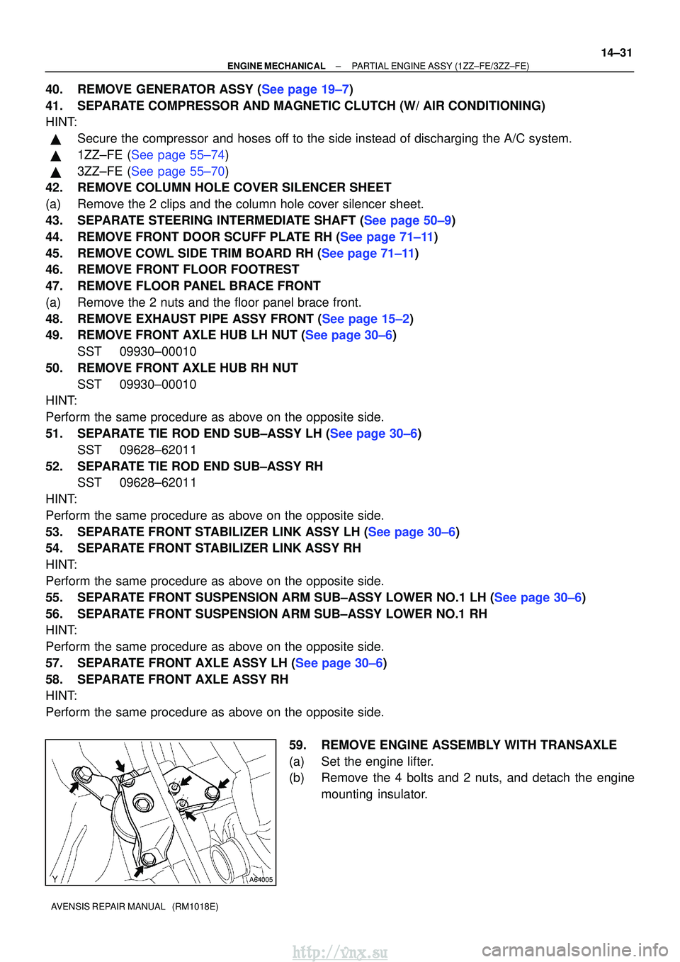
59. REMOVE ENGINE ASSEMBLY WITH TRANSAXLE
(a) Set the engine lifter.
(b) Remove the 4 bolts and 2 nuts, and detach the enginemounting insulator.
http://vnx.su
Page 688 of 2234
A76715
A76717
A76716
A62830Front SideRear Side
14±32
±
ENGINE MECHANICAL PARTIAL ENGINE ASSY (1ZZ±FE/3ZZ±FE)
AVENSIS REPAIR MANUAL (RM1018E)
(c) Remove the through bolt and nut, detach the engine mounting insulator from the vehicle.
(d) Remove the 2 bolts and 2 nuts as shown in the illustration.
(e) Remove the 8 bolts and the front suspension member brace rear RH and LH.
(f) Carefully remove the engine with transaxle from the en- gine compartment.
(g) Install the engine hanger No. 1 (12281±15040) and the bolt (91512±B1016).
Torque: 38 N �m (387 kgf� cm, 28 ft�lbf)
(h) Install the engine hanger (12281±22021) and the bolt
(91512±B1016).
Torque: 38 N� m (387 kgf�cm, 28 ft�lbf)
HINT:
Securely install the front engine hanger (12281±22021) and the
rear engine hanger No. 1 (12281±15040) to the engine assem-
bly.
(i) Attach the engine sling and hang the engine with the chain block.
http://vnx.su