Page 2507 of 4179
![NISSAN X-TRAIL 2003 Service Repair Manual REPAIR FOR COMPONENT PARTS
AT-471
[ALL]
D
E
F
G
H
I
J
K
L
MA
B
AT
High Clutch Drive Plates
�Check facing for burns, cracks or damage.
�Measure the thickness of facing.
�If not within wear limit, rep](/manual-img/5/57404/w960_57404-2506.png "NISSAN X-TRAIL 2003 Service Repair Manual REPAIR FOR COMPONENT PARTS
AT-471
[ALL]
D
E
F
G
H
I
J
K
L
MA
B
AT
High Clutch Drive Plates
�Check facing for burns, cracks or damage.
�Measure the thickness of facing.
�If not within wear limit, rep")
REPAIR FOR COMPONENT PARTS
AT-471
[ALL]
D
E
F
G
H
I
J
K
L
MA
B
AT
High Clutch Drive Plates
�Check facing for burns, cracks or damage.
�Measure the thickness of facing.
�If not within wear limit, replace.
High Clutch Piston
�Make sure that check balls are not fixed.
�Apply compressed air to check ball oil hole opposite return
spring. Make sure there is no air leakage.
�Apply compressed air to oil hole on return spring side to make
sure that air leaks past ball.
Seal Ring Clearance
�Install new seal rings onto input shaft assembly (high clutch
drum).
�Measure the clearance between seal ring and ring groove.
�If not within allowable limit, replace input shaft assembly.
ASSEMBLY
1. Install D-rings on high clutch piston.
CAUTION:
�Apply ATF to D-rings.
�Do not reuse D-rings.Thickness of drive plate:
Standard value 1.6 mm (0.063 in)
Wear limit 1.4 mm (0.055 in)
SAT162D
SAT186D
Standard clearance: 0.08 - 0.23 mm (0.0031 - 0.0091 in)
Allowable limit: 0.23 mm (0.0091 in)
SCIA4442E
SCIA4441E
Page 2508 of 4179
AT-472
[ALL]
REPAIR FOR COMPONENT PARTS
2. Install high clutch piston by turning it slowly.
CAUTION:
Apply ATF to inner surface of input shaft assembly (high
clutch drum).
3. Install return springs and spring retainer on high clutch piston.
4. Set SST on spring retainer and install snap ring while slowly
compressing return springs.
CAUTION:
�Set SST directly over return springs.
�Do not expand snap ring excessively.
CAUTION:
Do not align snap ring gap with spring retainer stopper.
S AT 111 F
SAT109F
SAT108FB
SAT113F
Page 2514 of 4179
AT-478
[ALL]
REPAIR FOR COMPONENT PARTS
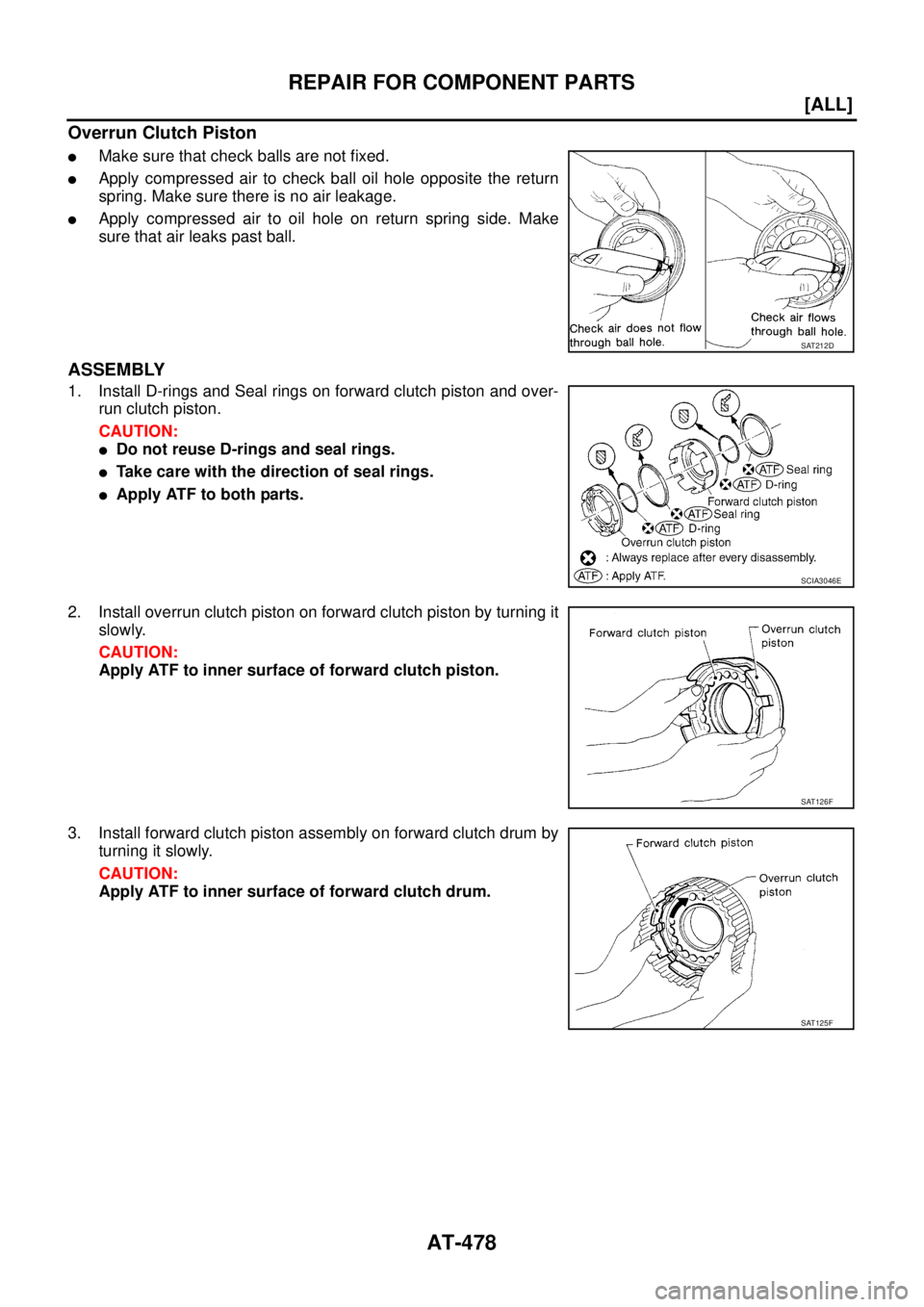
Overrun Clutch Piston
�Make sure that check balls are not fixed.
�Apply compressed air to check ball oil hole opposite the return
spring. Make sure there is no air leakage.
�Apply compressed air to oil hole on return spring side. Make
sure that air leaks past ball.
ASSEMBLY
1. Install D-rings and Seal rings on forward clutch piston and over-
run clutch piston.
CAUTION:
�Do not reuse D-rings and seal rings.
�Take care with the direction of seal rings.
�Apply ATF to both parts.
2. Install overrun clutch piston on forward clutch piston by turning it
slowly.
CAUTION:
Apply ATF to inner surface of forward clutch piston.
3. Install forward clutch piston assembly on forward clutch drum by
turning it slowly.
CAUTION:
Apply ATF to inner surface of forward clutch drum.
SAT212D
SCIA3046E
SAT126F
SAT125F
Page 2520 of 4179
AT-484
[ALL]
REPAIR FOR COMPONENT PARTS
6. In order to remove low & reverse brake piston, apply com-
pressed air to oil hole of retainer while holding low & reverse
brake piston.
CAUTION:
Apply air gradually and allow low & reverse brake piston to
come out evenly.
7. Remove D-rings from low & reverse brake piston.
INSPECTION
Low and Reverse Brake Snap Ring, Spring Retainer and Return Springs
�Check for deformation, fatigue or damage.
If necessary, replace.
�When replacing spring retainer and return springs, replace them as a set.
Low and Reverse Brake Drive Plate
�Check the facing for burns, cracks or damage.
�Measure the thickness of facing.
�If not within wear limit, replace.
ASSEMBLY
1. Install D-rings on piston.
CAUTION:
�Apply ATF to both parts.
�Do not reuse D-ring.
SCIA3651E
SCIA4381E
Thickness of drive plate:
Standard value 1.8 mm (0.071 in)
Wear limit 1.6 mm (0.063 in)
SAT162D
SCIA2998E
Page 2521 of 4179
REPAIR FOR COMPONENT PARTS
AT-485
[ALL]
D
E
F
G
H
I
J
K
L
MA
B
AT
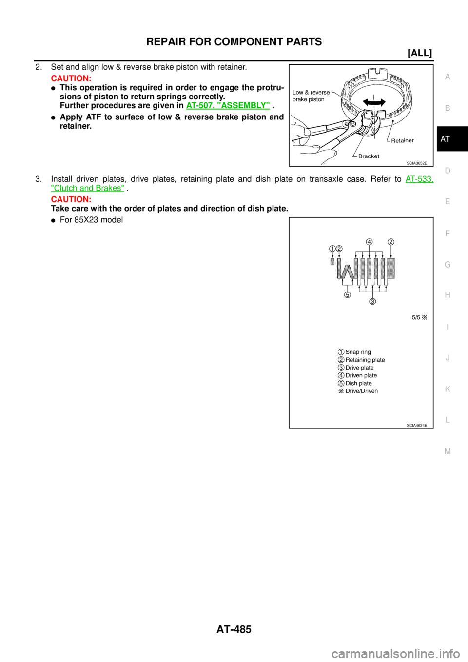
2. Set and align low & reverse brake piston with retainer.
CAUTION:
�This operation is required in order to engage the protru-
sions of piston to return springs correctly.
Further procedures are given in AT- 5 0 7 , "
ASSEMBLY" .
�Apply ATF to surface of low & reverse brake piston and
retainer.
3. Install driven plates, drive plates, retaining plate and dish plate on transaxle case. Refer to AT- 5 3 3 ,
"Clutch and Brakes" .
CAUTION:
Take care with the order of plates and direction of dish plate.
�For 85X23 model
SCIA3652E
SCIA4624E
Page 2530 of 4179
AT-494
[ALL]
REPAIR FOR COMPONENT PARTS
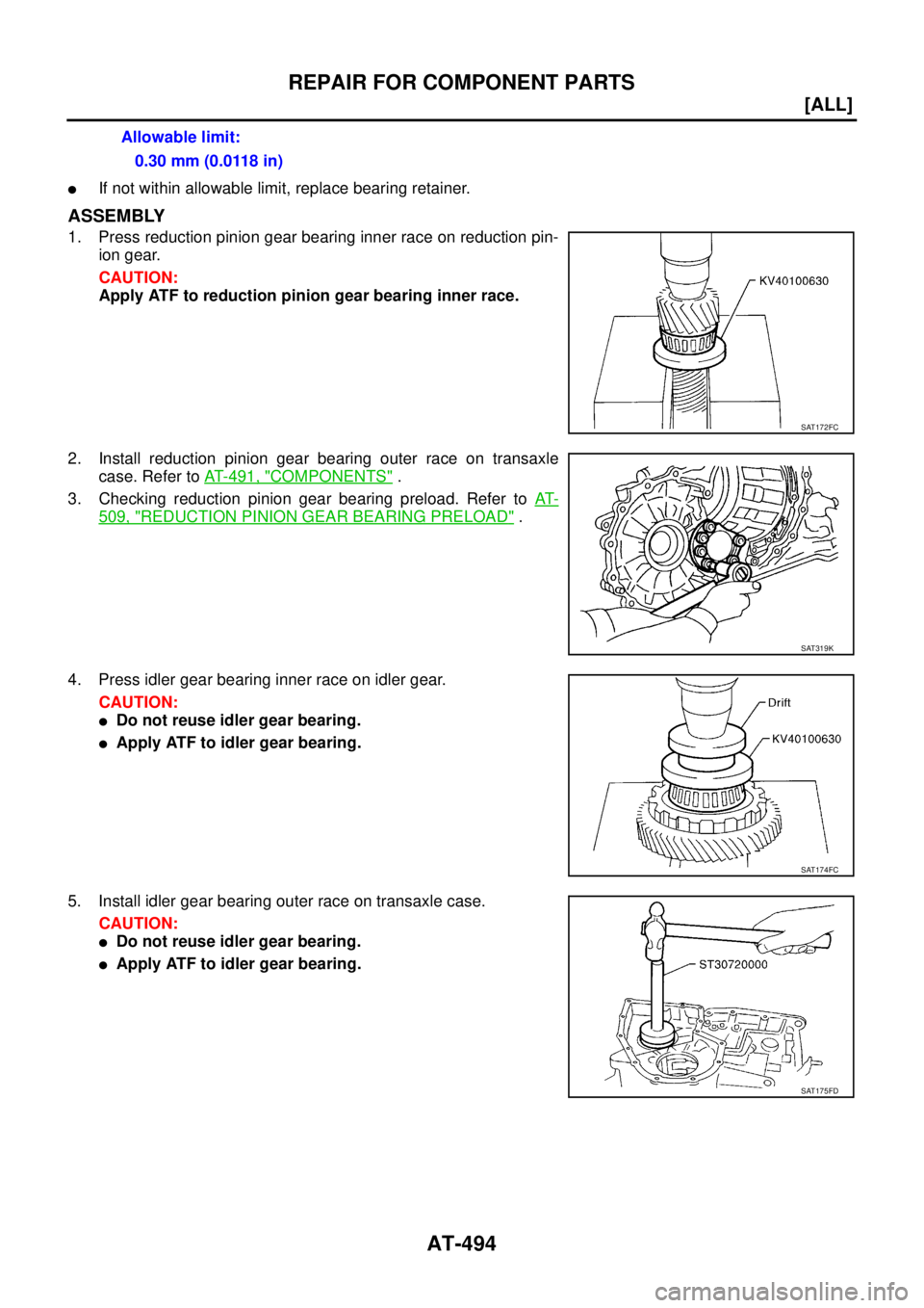
�If not within allowable limit, replace bearing retainer.
ASSEMBLY
1. Press reduction pinion gear bearing inner race on reduction pin-
ion gear.
CAUTION:
Apply ATF to reduction pinion gear bearing inner race.
2. Install reduction pinion gear bearing outer race on transaxle
case. Refer to AT- 4 9 1 , "
COMPONENTS" .
3. Checking reduction pinion gear bearing preload. Refer to AT-
509, "REDUCTION PINION GEAR BEARING PRELOAD" .
4. Press idler gear bearing inner race on idler gear.
CAUTION:
�Do not reuse idler gear bearing.
�Apply ATF to idler gear bearing.
5. Install idler gear bearing outer race on transaxle case.
CAUTION:
�Do not reuse idler gear bearing.
�Apply ATF to idler gear bearing.Allowable limit:
0.30 mm (0.0118 in)
SAT172FC
SAT319K
SAT174FC
SAT175FD
Page 2531 of 4179
REPAIR FOR COMPONENT PARTS
AT-495
[ALL]
D
E
F
G
H
I
J
K
L
MA
B
AT
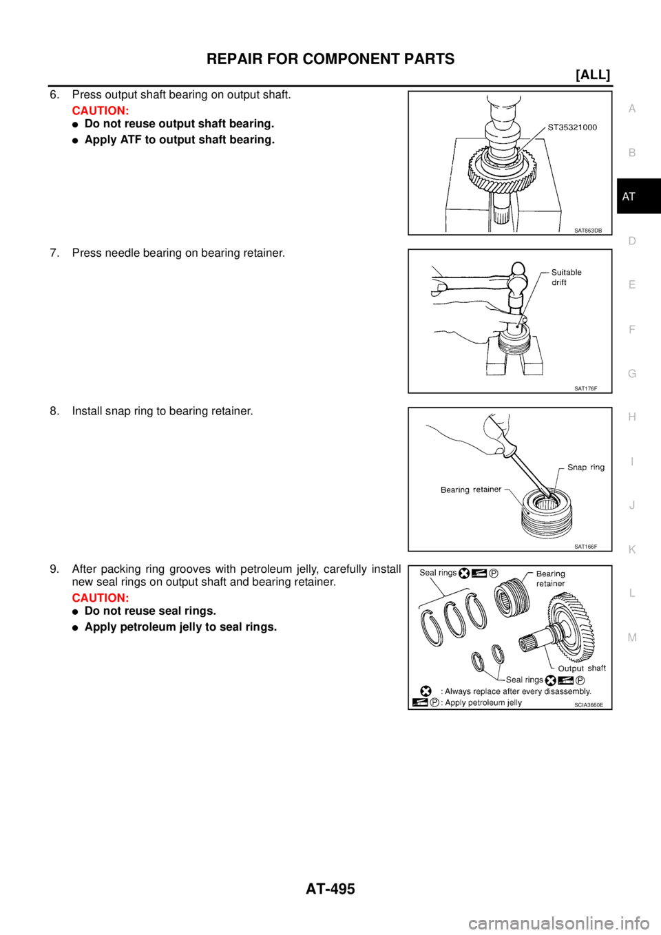
6. Press output shaft bearing on output shaft.
CAUTION:
�Do not reuse output shaft bearing.
�Apply ATF to output shaft bearing.
7. Press needle bearing on bearing retainer.
8. Install snap ring to bearing retainer.
9. After packing ring grooves with petroleum jelly, carefully install
new seal rings on output shaft and bearing retainer.
CAUTION:
�Do not reuse seal rings.
�Apply petroleum jelly to seal rings.
SAT863DB
SAT176F
SAT166F
SCIA3660E
Page 2536 of 4179
AT-500
[ALL]
REPAIR FOR COMPONENT PARTS
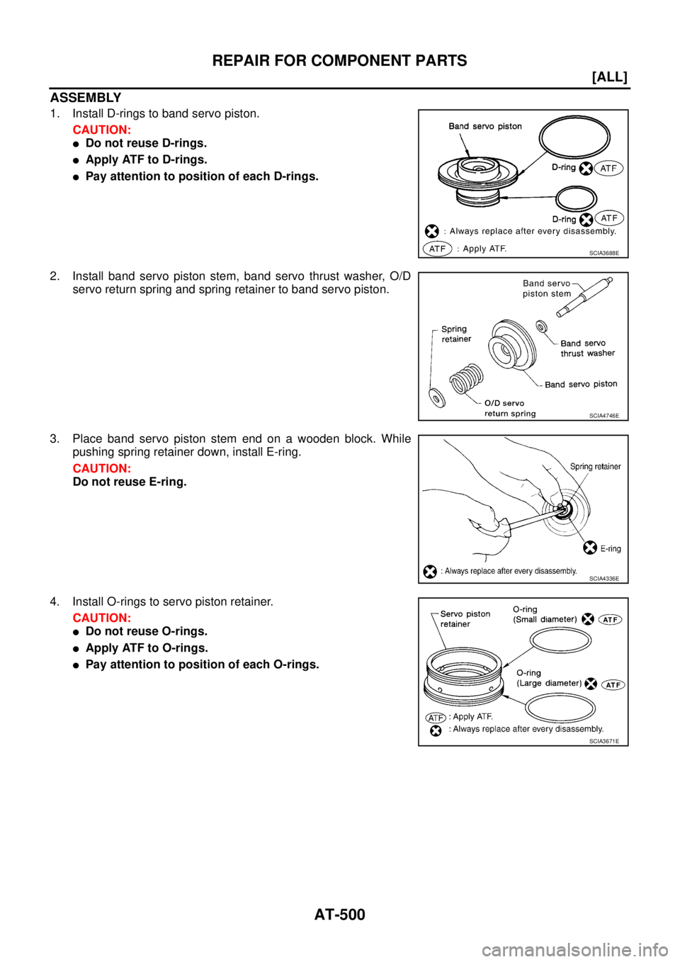
ASSEMBLY
1. Install D-rings to band servo piston.
CAUTION:
�Do not reuse D-rings.
�Apply ATF to D-rings.
�Pay attention to position of each D-rings.
2. Install band servo piston stem, band servo thrust washer, O/D
servo return spring and spring retainer to band servo piston.
3. Place band servo piston stem end on a wooden block. While
pushing spring retainer down, install E-ring.
CAUTION:
Do not reuse E-ring.
4. Install O-rings to servo piston retainer.
CAUTION:
�Do not reuse O-rings.
�Apply ATF to O-rings.
�Pay attention to position of each O-rings.
SCIA3688E
SCIA4746E
SCIA4336E
SCIA3671E
![NISSAN X-TRAIL 2003 Service Repair Manual AT-472
[ALL]
REPAIR FOR COMPONENT PARTS
2. Install high clutch piston by turning it slowly.
CAUTION:
Apply ATF to inner surface of input shaft assembly (high
clutch drum).
3. Install return springs](/manual-img/5/57404/w960_57404-2507.png "NISSAN X-TRAIL 2003 Service Repair Manual AT-472
[ALL]
REPAIR FOR COMPONENT PARTS
2. Install high clutch piston by turning it slowly.
CAUTION:
Apply ATF to inner surface of input shaft assembly (high
clutch drum).
3. Install return springs")
![NISSAN X-TRAIL 2003 Service Repair Manual AT-484
[ALL]
REPAIR FOR COMPONENT PARTS
6. In order to remove low & reverse brake piston, apply com-
pressed air to oil hole of retainer while holding low & reverse
brake piston.
CAUTION:
Apply air](/manual-img/5/57404/w960_57404-2519.png "NISSAN X-TRAIL 2003 Service Repair Manual AT-484
[ALL]
REPAIR FOR COMPONENT PARTS
6. In order to remove low & reverse brake piston, apply com-
pressed air to oil hole of retainer while holding low & reverse
brake piston.
CAUTION:
Apply air")