Page 1918 of 4179

CL-4
NOISE, VIBRATION AND HARSHNESS (NVH) TROUBLESHOOTING
NOISE, VIBRATION AND HARSHNESS (NVH) TROUBLESHOOTINGPFP:00003
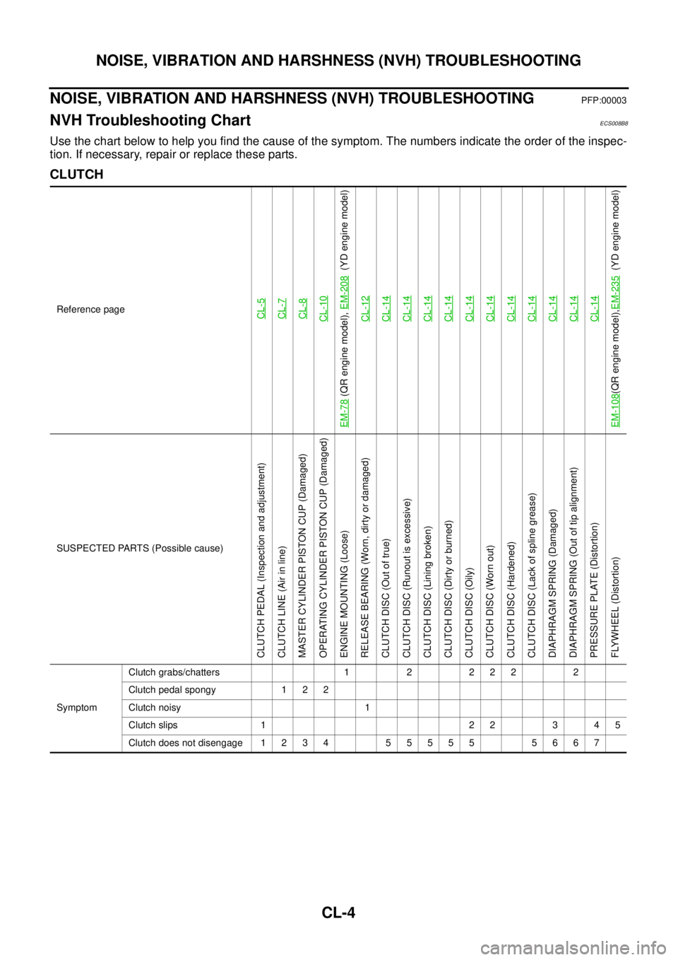
NVH Troubleshooting ChartECS008B8
Use the chart below to help you find the cause of the symptom. The numbers indicate the order of the inspec-
tion. If necessary, repair or replace these parts.
CLUTCH
Reference pageCL-5CL-7CL-8CL-10
EM-78
(QR engine model), EM-208
(YD engine model)
CL-12
CL-14CL-14CL-14CL-14CL-14CL-14CL-14CL-14CL-14CL-14CL-14
EM-108
(QR engine model),EM-235
(YD engine model)
SUSPECTED PARTS (Possible cause)
CLUTCH PEDAL (Inspection and adjustment)
CLUTCH LINE (Air in line)
MASTER CYLINDER PISTON CUP (Damaged)
OPERATING CYLINDER PISTON CUP (Damaged)
ENGINE MOUNTING (Loose)
RELEASE BEARING (Worn, dirty or damaged)
CLUTCH DISC (Out of true)
CLUTCH DISC (Runout is excessive)
CLUTCH DISC (Lining broken)
CLUTCH DISC (Dirty or burned)
CLUTCH DISC (Oily)
CLUTCH DISC (Worn out)
CLUTCH DISC (Hardened)
CLUTCH DISC (Lack of spline grease)
DIAPHRAGM SPRING (Damaged)
DIAPHRAGM SPRING (Out of tip alignment)
PRESSURE PLATE (Distortion)
FLYWHEEL (Distortion)
SymptomClutch grabs/chatters 1 2 2 2 2 2
Clutch pedal spongy 1 2 2
Clutch noisy 1
Clutch slips 1 2 2 3 4 5
Clutch does not disengage 1 2 3 4 5 5 5 5 5 5 6 6 7
Page 2696 of 4179

FAX-2
PRECAUTIONS
PRECAUTIONSPFP:00001
CautionEDS0005P
�When installing rubber parts, final tightening must be carried out under unladen condition* with tires on
ground.
�Oil will shorten the life of rubber bushes. Be sure to wipe off any spilled oil.
*: Fuel, radiator coolant and engine oil full. Spare tire, jack, hand tools and mats in designated positions.
�After installing removed suspension parts, check wheel alignment and adjust if necessary.
Observe the following precautions when disassembling and servicing drive shaft.
�Perform work in a location which is as dust-free as possible.
�Before disassembling and servicing, clean the outside of parts.
�Prevention of the entry of foreign objects must be taken into account during disassembly of the service
location.
�Disassembled parts must be carefully reassembled in the correct order. If work is interrupted, a clean
cover must be placed over parts.
�Paper shop cloths must be used. Fabric shop cloths must not be used because of the danger of lint adher-
ing to parts.
�Disassembled parts (except for rubber parts) should be cleaned with kerosene which shall be removed by
blowing with air or wiping with paper shop cloths.
Page 2716 of 4179

RAX-2
PRECAUTIONS
PRECAUTIONSPFP:00001
CautionEDS00060
�When installing rubber parts, final tightening must be carried out under unladen condition* with tires on
ground.
*: Fuel, radiator coolant and engine oil full. Spare tire, jack, hand tools and mats in designated positions.
�After installing removed suspension parts, check wheel alignment and adjust if necessary.
Observe the following precautions when disassembling and servicing drive shaft.
�Perform work in a location which is as dust-free and dirt-free as possible.
�Before disassembling and servicing, clean the outside of parts.
�The disassembly and service location must be clean. Care must be taken to prevent parts from becoming
dirty and to prevent the entry of foreign objects.
�Disassembled parts must be carefully reassembled in the correct order. If work is interrupted, a clean
cover must be placed over parts.
�Paper shop cloths must be used. Fabric shop cloths must not be used because of the danger of lint adher-
ing to parts.
�Disassembled parts (except for rubber parts) should be cleaned with kerosene which shall be removed by
blowing with air or wiping with paper shop cloths.
Page 2725 of 4179

REAR DRIVE SHAFT
RAX-11
C
E
F
G
H
I
J
K
L
MA
B
RAX
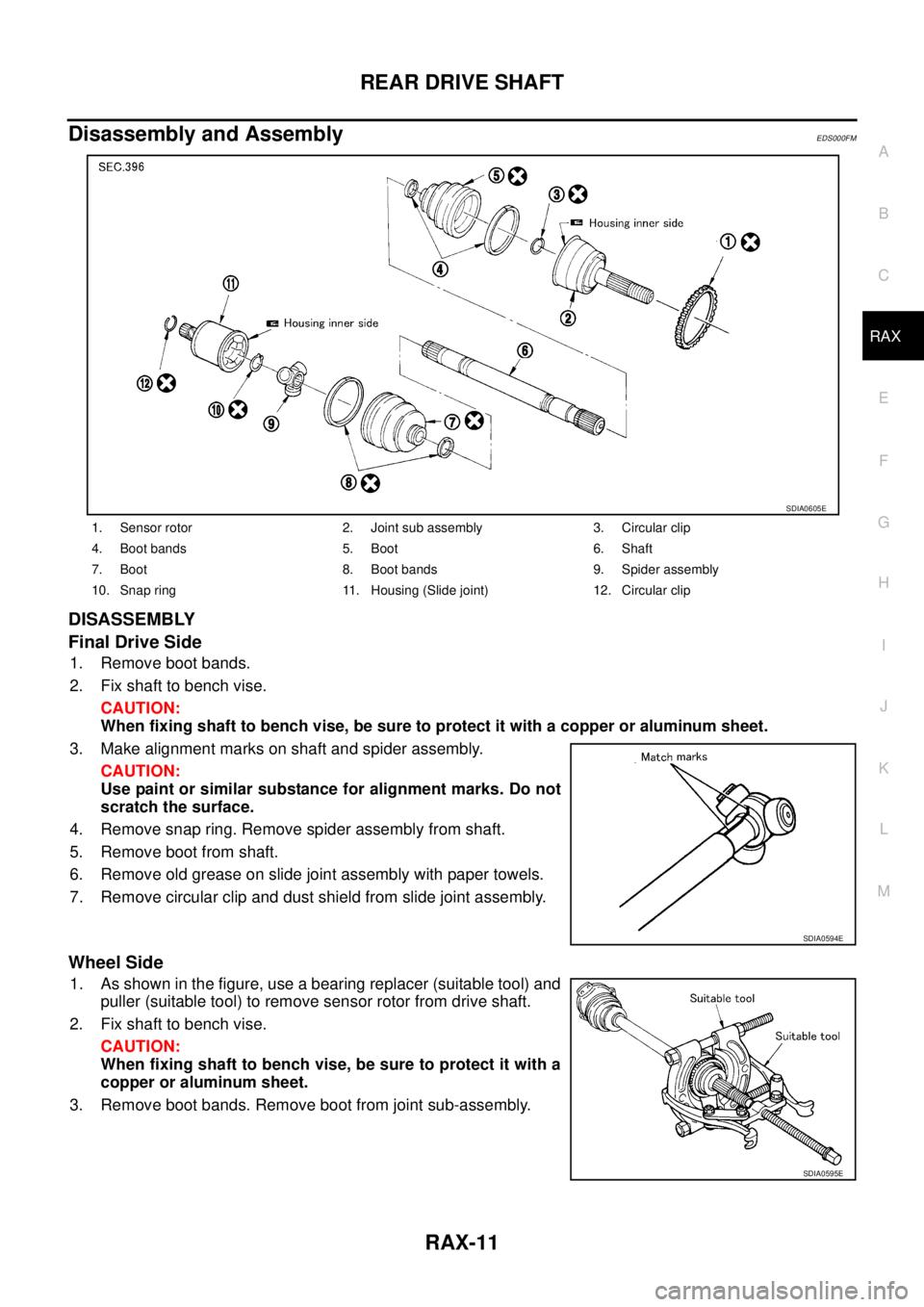
Disassembly and AssemblyEDS000FM
DISASSEMBLY
Final Drive Side
1. Remove boot bands.
2. Fix shaft to bench vise.
CAUTION:
When fixing shaft to bench vise, be sure to protect it with a copper or aluminum sheet.
3. Make alignment marks on shaft and spider assembly.
CAUTION:
Use paint or similar substance for alignment marks. Do not
scratch the surface.
4. Remove snap ring. Remove spider assembly from shaft.
5. Remove boot from shaft.
6. Remove old grease on slide joint assembly with paper towels.
7. Remove circular clip and dust shield from slide joint assembly.
Wheel Side
1. As shown in the figure, use a bearing replacer (suitable tool) and
puller (suitable tool) to remove sensor rotor from drive shaft.
2. Fix shaft to bench vise.
CAUTION:
When fixing shaft to bench vise, be sure to protect it with a
copper or aluminum sheet.
3. Remove boot bands. Remove boot from joint sub-assembly.
1. Sensor rotor 2. Joint sub assembly 3. Circular clip
4. Boot bands 5. Boot 6. Shaft
7. Boot 8. Boot bands 9. Spider assembly
10. Snap ring 11. Housing (Slide joint) 12. Circular clip
SDIA0605E
SDIA0594E
SDIA0595E
Page 2731 of 4179

FSU-1
FRONT SUSPENSION
E SUSPENSION
CONTENTS
C
D
F
G
H
I
J
K
L
M
SECTION
A
B
FSU
FRONT SUSPENSION
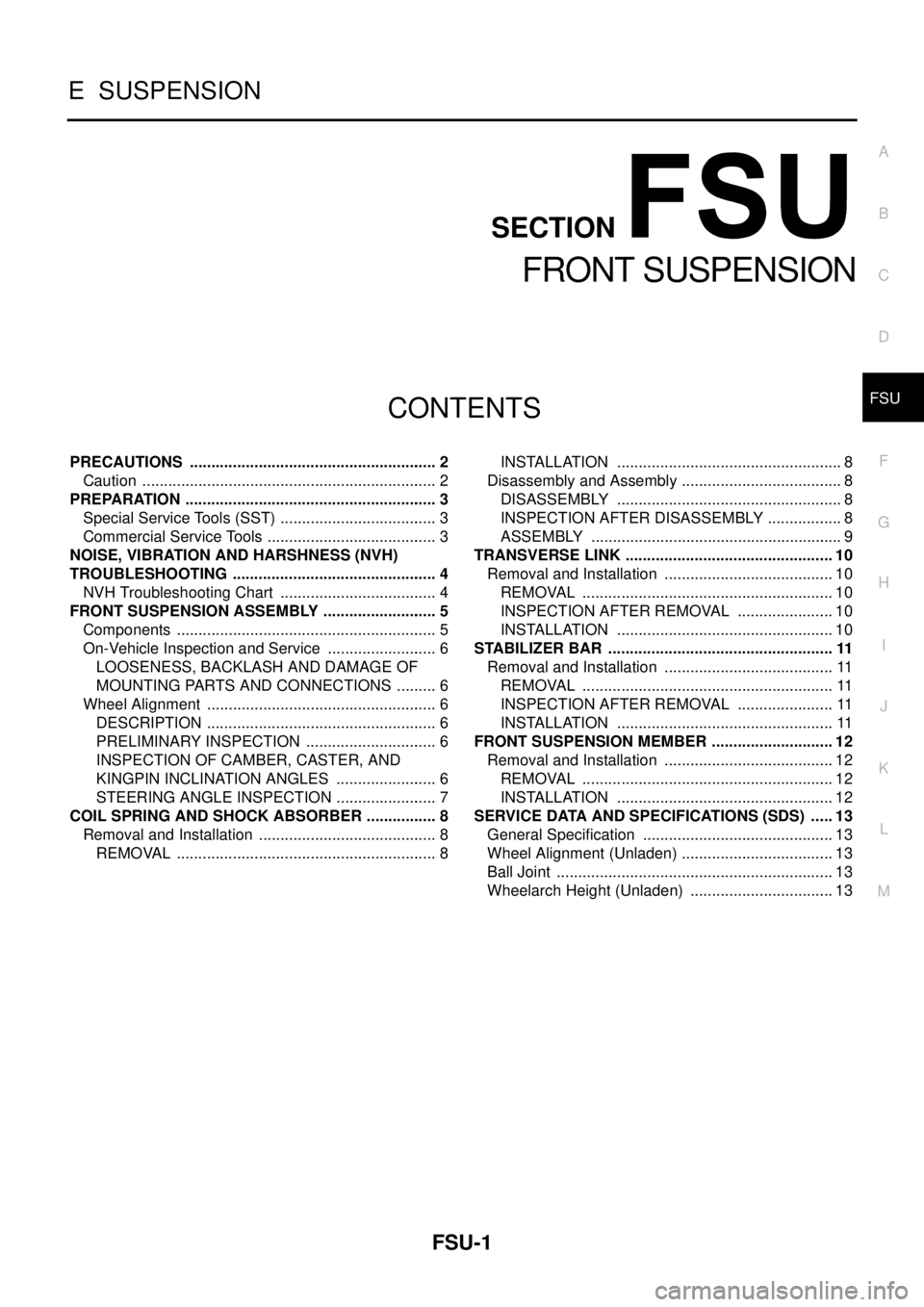
PRECAUTIONS .......................................................... 2
Caution ..................................................................... 2
PREPARATION ........................................................... 3
Special Service Tools (SST) ..................................... 3
Commercial Service Tools ........................................ 3
NOISE, VIBRATION AND HARSHNESS (NVH)
TROUBLESHOOTING ................................................ 4
NVH Troubleshooting Chart ..................................... 4
FRONT SUSPENSION ASSEMBLY ........................... 5
Components ............................................................. 5
On-Vehicle Inspection and Service .......................... 6
LOOSENESS, BACKLASH AND DAMAGE OF
MOUNTING PARTS AND CONNECTIONS .......... 6
Wheel Alignment ...................................................... 6
DESCRIPTION ...................................................... 6
PRELIMINARY INSPECTION ............................... 6
INSPECTION OF CAMBER, CASTER, AND
KINGPIN INCLINATION ANGLES ........................ 6
STEERING ANGLE INSPECTION ........................ 7
COIL SPRING AND SHOCK ABSORBER ................. 8
Removal and Installation .......................................... 8
REMOVAL ............................................................. 8INSTALLATION ..................................................... 8
Disassembly and Assembly ...................................... 8
DISASSEMBLY ..................................................... 8
INSPECTION AFTER DISASSEMBLY .................. 8
ASSEMBLY ........................................................... 9
TRANSVERSE LINK ................................................. 10
Removal and Installation ........................................ 10
REMOVAL ........................................................... 10
INSPECTION AFTER REMOVAL ....................... 10
INSTALLATION ................................................... 10
STABILIZER BAR ..................................................... 11
Removal and Installation ........................................ 11
REMOVAL ........................................................... 11
INSPECTION AFTER REMOVAL ....................... 11
INSTALLATION ................................................... 11
FRONT SUSPENSION MEMBER ............................. 12
Removal and Installation ........................................ 12
REMOVAL ........................................................... 12
INSTALLATION ................................................... 12
SERVICE DATA AND SPECIFICATIONS (SDS) ...... 13
General Specification ............................................. 13
Wheel Alignment (Unladen) .................................... 13
Ball Joint ................................................................. 13
Wheelarch Height (Unladen) .................................. 13
Page 2732 of 4179
FSU-2
PRECAUTIONS
PRECAUTIONSPFP:00001
CautionEES0006Z
�When installing rubber bushings, final tightening must be carried out under unladen conditions with tires
on flat, level ground. Oil will shorten the life of rubber bushings. Be sure to wipe off any spilled oil.
�“Unladen condition” means that fuel, coolant and lubricant are full and ready for drive. However, spare tire,
jack, and hand tools should be unloaded.
�After installing the removed suspension parts, always check wheel alignment and adjust if necessary.
�Replace the caulking nut with a new one. Install a new nut without wiping the oil off before tightening.
Page 2733 of 4179
PREPARATION
FSU-3
C
D
F
G
H
I
J
K
L
MA
B
FSU
PREPARATIONPFP:00002
Special Service Tools (SST)EES00070
Commercial Service ToolsEES000JC
Tool number
Tool nameDescription
HT7252000
Ball joint removerRemoving tie-rod outer and lower ball
joint
ST3127S000
Preload gaugeMeasuring ball joint sliding torque
KV991040S1
CCK gauge attachment
1. KV99104020 Adapter A
2. KV99104030 Adapter B
3. KV99104040 Adapter C
4. KV99104050 Adapter D
5. KV99104060 Plate
6. KV99104070 Guide bolt
7. KV99104080 Spring
8. KV99104090 Center plateMeasuring wheel alignment
ST35652000
Strut attachmentDisassembling and assembling strut
S-NT146
ZZA0806D
ZZA1167D
ZZA0807D
Tool nameDescription
Attachment wheel alignment
a: screw M24 x 1.5 pitch
b: 35 mm (1.38 in) dia.
c: 65 mm (2.56 in) dia.
d: 56 mm (2.20 in) dia.
e: 12 mm (0.47 in) dia.Measure wheel alignment
S-NT148
Page 2734 of 4179

FSU-4
NOISE, VIBRATION AND HARSHNESS (NVH) TROUBLESHOOTING
NOISE, VIBRATION AND HARSHNESS (NVH) TROUBLESHOOTINGPFP:00003
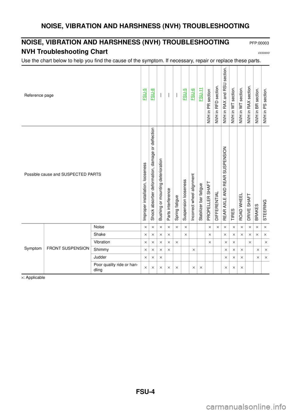
NVH Troubleshooting ChartEES000ID
Use the chart below to help you find the cause of the symptom. If necessary, repair or replace these parts.
×: ApplicableReference page
FSU-5 FSU-8—
—
—
FSU-5 FSU-6 FSU-11
NVH in PR section
NVH in RFD section.
NVH in RAX and RSU section.
NVH in WT section.
NVH in WT section.
NVH in RAX section.
NVH in BR section.
NVH in PS section.
Possible cause and SUSPECTED PARTS
Improper installation, looseness
Shock absorber deformation, damage or deflection
Bushing or mounting deterioration
Parts interference
Spring fatigue
Suspension looseness
Incorrect wheel alignment
Stabilizer bar fatigue
PROPELLER SHAFT
DIFFERENTIAL
REAR AXLE AND REAR SUSPENSION
TIRES
ROAD WHEEL
DRIVE SHAFT
BRAKES
STEERING
Symptom FRONT SUSPENSIONNoise××××× × ××× ×××××
Shake×××× × × × ×××××
Vibration××××× × ×× × ×
Shimmy×××× × ××× ××
Judder××× ××× ××
Poor quality ride or han-
dling×× × × × ×× × × ×