Page 2447 of 4179
ON-VEHICLE SERVICE
AT-411
[ALL]
D
E
F
G
H
I
J
K
L
MA
B
AT
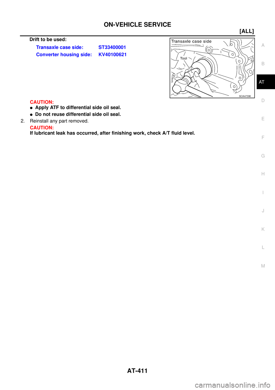
Drift to be used:
CAUTION:
�Apply ATF to differential side oil seal.
�Do not reuse differential side oil seal.
2. Reinstall any part removed.
CAUTION:
If lubricant leak has occurred, after finishing work, check A/T fluid level.Transaxle case side: ST33400001
Converter housing side: KV40100621
SCIA4739E
Page 2460 of 4179
AT-424
[ALL]
DISASSEMBLY
DISASSEMBLYPFP:31020
DisassemblyECS004LZ
1. Drain ATF through drain plug.
2. Remove torque converter.
3. Check torque converter one-way clutch using check tool as
shown in the right figure.
a. Insert check tool into the groove of bearing support built into
one-way clutch outer race.
b. When fixing bearing support with check tool, rotate one- way
clutch spline using screwdriver.
c. Check that inner race rotates clockwise only. If not, replace
torque converter assembly.
SCIA0003E
SAT008D
SAT009D
Page 2477 of 4179
REPAIR FOR COMPONENT PARTS
AT-441
[ALL]
D
E
F
G
H
I
J
K
L
MA
B
AT
3. Drive and pull out parking rod plate retaining pin.
4. Remove parking rod plate (with parking rod) from manual shaft.
5. Draw out parking rod (with parking rod plate) from transaxle
case.
6. Remove parking rod from parking rod plate.
7. Pull out manual shaft retaining pin.
8. Remove manual shaft and manual plate from transaxle case.
9. Remove manual shaft oil seal.
CAUTION:
Be careful not to scratch transaxle case.
INSPECTION
�Check component parts for wear or damage. Replace if necessary.
INSTALLATION
1. Use a drift [commercial service tool φ 22 mm (0.87 in)] to drive
manual shaft oil seal into the transaxle case.
CAUTION:
�Do not reuse manual shaft oil seal.
�Apply ATF to outer surface of manual shaft oil seal.
2. Install parking rod to parking rod plate.
SAT043FC
SAT049F
SAT080D
SAT081D
Page 2482 of 4179
AT-446
[ALL]
REPAIR FOR COMPONENT PARTS
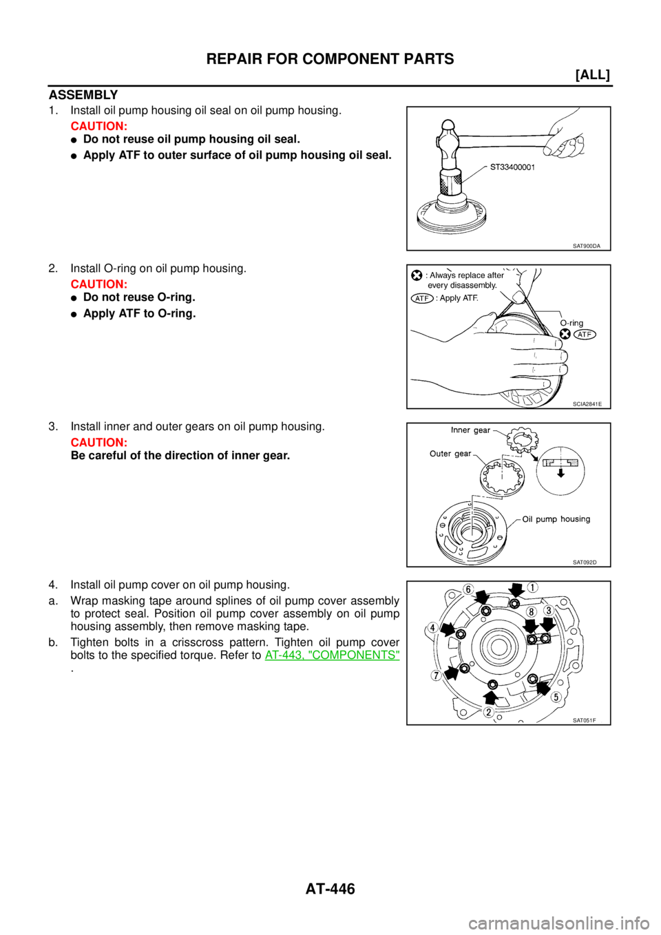
ASSEMBLY
1. Install oil pump housing oil seal on oil pump housing.
CAUTION:
�Do not reuse oil pump housing oil seal.
�Apply ATF to outer surface of oil pump housing oil seal.
2. Install O-ring on oil pump housing.
CAUTION:
�Do not reuse O-ring.
�Apply ATF to O-ring.
3. Install inner and outer gears on oil pump housing.
CAUTION:
Be careful of the direction of inner gear.
4. Install oil pump cover on oil pump housing.
a. Wrap masking tape around splines of oil pump cover assembly
to protect seal. Position oil pump cover assembly on oil pump
housing assembly, then remove masking tape.
b. Tighten bolts in a crisscross pattern. Tighten oil pump cover
bolts to the specified torque. Refer to AT- 4 4 3 , "
COMPONENTS"
.
SAT900DA
SCIA2841E
SAT092D
SAT051F
Page 2491 of 4179
REPAIR FOR COMPONENT PARTS
AT-455
[ALL]
D
E
F
G
H
I
J
K
L
MA
B
AT
2. Install O-rings to solenoid valves and terminal body.
CAUTION:
�Do not reuse O-rings.
�Apply ATF to O-rings.
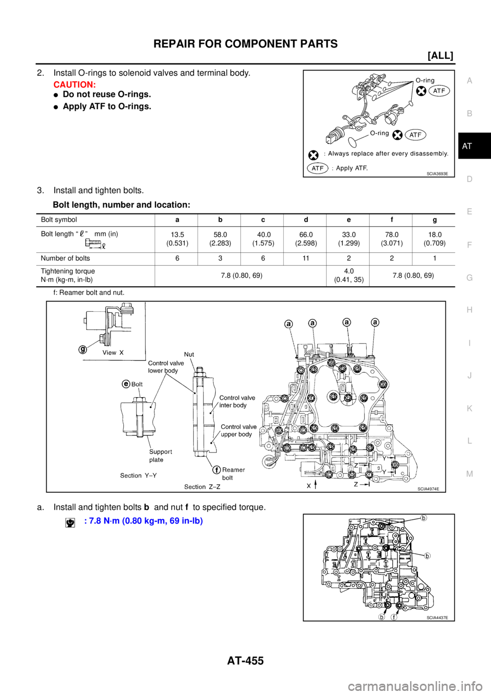
3. Install and tighten bolts.
Bolt length, number and location:
f: Reamer bolt and nut.
a. Install and tighten bolts b and nut f to specified torque.
SCIA3693E
Bolt symbolabcde f g
Bolt length “ ” mm (in)
13.5
(0.531)58.0
(2.283) 40.0
(1.575)66.0
(2.598)33.0
(1.299)78.0
(3.071)18.0
(0.709)
Number of bolts 6 3 6 11 2 2 1
Tightening torque
N·m (kg-m, in-lb)7.8 (0.80, 69)4.0
(0.41, 35)7.8 (0.80, 69)
SCIA4974E
: 7.8 N·m (0.80 kg-m, 69 in-lb)
SCIA4437E
Page 2495 of 4179
![NISSAN X-TRAIL 2003 Service Repair Manual REPAIR FOR COMPONENT PARTS
AT-459
[ALL]
D
E
F
G
H
I
J
K
L
MA
B
AT
c. Place mating surface of valve body face down, and remove
internal parts.
CAUTION:
�If a valve is hard to remove, place valve body](/manual-img/5/57404/w960_57404-2494.png "NISSAN X-TRAIL 2003 Service Repair Manual REPAIR FOR COMPONENT PARTS
AT-459
[ALL]
D
E
F
G
H
I
J
K
L
MA
B
AT
c. Place mating surface of valve body face down, and remove
internal parts.
CAUTION:
�If a valve is hard to remove, place valve body")
REPAIR FOR COMPONENT PARTS
AT-459
[ALL]
D
E
F
G
H
I
J
K
L
MA
B
AT
c. Place mating surface of valve body face down, and remove
internal parts.
CAUTION:
�If a valve is hard to remove, place valve body face down
and lightly tap it with a soft hammer.
�Be careful not to drop or damage valves and sleeves.
INSPECTION
Valve Spring
�Measure free length and outer diameter of each valve spring.
Also check for damage or deformation. Refer to AT- 5 3 0 , "
SER-
VICE DATA AND SPECIFICATIONS (SDS)" .
�Replace valve springs if deformed or fatigued.
Control Valves
�Check sliding surfaces of valves, sleeves and plugs.
ASSEMBLY
CAUTION:
�Apply ATF to all components before installation.
�Lay control valve body down when installing valves. Do not
stand control valve body upright.
�Lubricate control valve body and all valves with ATF. Install con-
trol valves by sliding them carefully into their bores.
CAUTION:
�Install each control valve one by one.
�Install control valves after checking, because some of
them are similar.
�Be careful not to scratch or damage valve body.
SAT137D
SAT138D
SAT139D
SAT140DA
Page 2498 of 4179
![NISSAN X-TRAIL 2003 Service Repair Manual AT-462
[ALL]
REPAIR FOR COMPONENT PARTS
DISASSEMBLY
�Remove valves at retainer plates.
For removal procedures, refer to AT- 4 5 8 , "
DISASSEMBLY" .
INSPECTION
Valve Springs
�Check each valve sprin](/manual-img/5/57404/w960_57404-2497.png "NISSAN X-TRAIL 2003 Service Repair Manual AT-462
[ALL]
REPAIR FOR COMPONENT PARTS
DISASSEMBLY
�Remove valves at retainer plates.
For removal procedures, refer to AT- 4 5 8 , \"
DISASSEMBLY\" .
INSPECTION
Valve Springs
�Check each valve sprin")
AT-462
[ALL]
REPAIR FOR COMPONENT PARTS
DISASSEMBLY
�Remove valves at retainer plates.
For removal procedures, refer to AT- 4 5 8 , "
DISASSEMBLY" .
INSPECTION
Valve Springs
�Check each valve spring for damage or deformation. Also mea-
sure free length and outer diameter. Refer to AT- 5 3 0 , "
SERVICE
DATA AND SPECIFICATIONS (SDS)" .
�Replace valve springs if deformed or fatigued.
Control Valves
�Check sliding surfaces of control valves, sleeves and plugs for damage.
ASSEMBLY
CAUTION:
�Apply ATF to all components before installation.
�Lay control valve body down when installing valves. Do not
stand control valve body upright.
1. Retainer plate 2. Pressure modifier piston spring 3. Pressure modifier piston
4. Parallel pin 5. Sleeve 6. Pressure modifier valve spring
7. Pressure modifier valve 8. Control valve lower body 9. Manual valve
10. Pressure regulator valve 11. Pressure regulator valve spring 12. Spring seat
13. Plug 14. Retainer plate 15. Sleeve
16. Overrun clutch control valve spring 17. Overrun clutch control valve 18. Plug
19. Retainer plate 20. Accumulator control valve spring 21. Accumulator control valve
22. Plug 23. Retainer plate 24. Retainer plate
25. Shift valve A spring 26. Shift valve A 27. Retainer plate
28. Plug 29. Shuttle plug 30. Shuttle valve spring
31. Shuttle valve 32. Shift valve B spring 33. Shift valve B
34. Plug 35. Retainer plate
SCIA4978E
SAT138D
SAT139D
Page 2502 of 4179
AT-466
[ALL]
REPAIR FOR COMPONENT PARTS
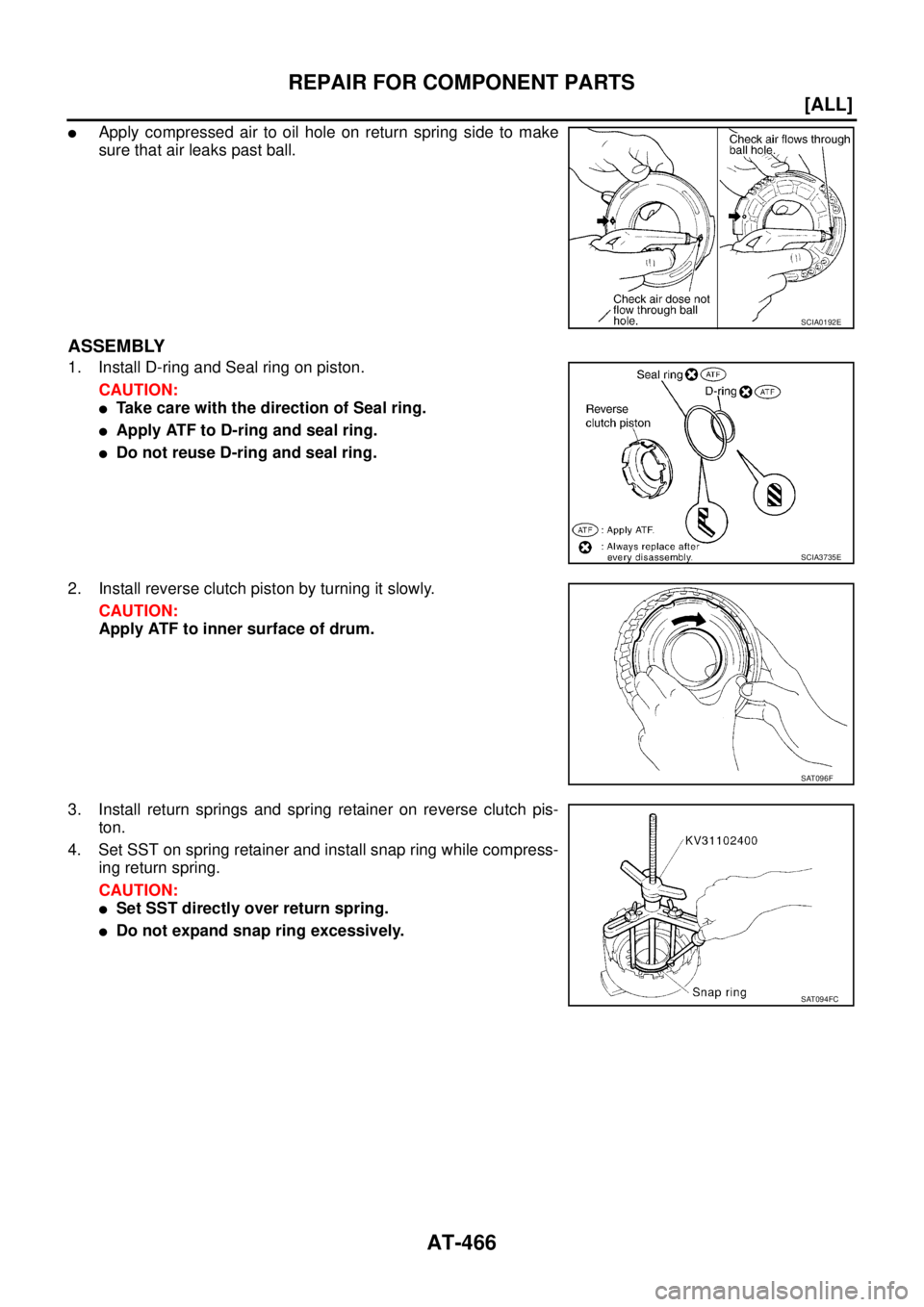
�Apply compressed air to oil hole on return spring side to make
sure that air leaks past ball.
ASSEMBLY
1. Install D-ring and Seal ring on piston.
CAUTION:
�Take care with the direction of Seal ring.
�Apply ATF to D-ring and seal ring.
�Do not reuse D-ring and seal ring.
2. Install reverse clutch piston by turning it slowly.
CAUTION:
Apply ATF to inner surface of drum.
3. Install return springs and spring retainer on reverse clutch pis-
ton.
4. Set SST on spring retainer and install snap ring while compress-
ing return spring.
CAUTION:
�Set SST directly over return spring.
�Do not expand snap ring excessively.
SCIA0192E
SCIA3735E
SAT096F
SAT094FC
![NISSAN X-TRAIL 2003 Service Repair Manual AT-424
[ALL]
DISASSEMBLY
DISASSEMBLYPFP:31020
DisassemblyECS004LZ
1. Drain ATF through drain plug.
2. Remove torque converter.
3. Check torque converter one-way clutch using check tool as
shown in t](/manual-img/5/57404/w960_57404-2459.png "NISSAN X-TRAIL 2003 Service Repair Manual AT-424
[ALL]
DISASSEMBLY
DISASSEMBLYPFP:31020
DisassemblyECS004LZ
1. Drain ATF through drain plug.
2. Remove torque converter.
3. Check torque converter one-way clutch using check tool as
shown in t")
![NISSAN X-TRAIL 2003 Service Repair Manual REPAIR FOR COMPONENT PARTS
AT-441
[ALL]
D
E
F
G
H
I
J
K
L
MA
B
AT
3. Drive and pull out parking rod plate retaining pin.
4. Remove parking rod plate (with parking rod) from manual shaft.
5. Draw out](/manual-img/5/57404/w960_57404-2476.png "NISSAN X-TRAIL 2003 Service Repair Manual REPAIR FOR COMPONENT PARTS
AT-441
[ALL]
D
E
F
G
H
I
J
K
L
MA
B
AT
3. Drive and pull out parking rod plate retaining pin.
4. Remove parking rod plate (with parking rod) from manual shaft.
5. Draw out")