Page 2081 of 4179
![NISSAN X-TRAIL 2003 Service Repair Manual ON BOARD DIAGNOSTIC SYSTEM DESCRIPTION
AT-45
[EURO-OBD]
D
E
F
G
H
I
J
K
L
MA
B
AT
SELF-DIAGNOSTIC PROCEDURE (WITH CONSULT-II)
1. Turn on CONSULT-II and touch “ENGINE” for EURO-OBD
detected item](/manual-img/5/57404/w960_57404-2080.png "NISSAN X-TRAIL 2003 Service Repair Manual ON BOARD DIAGNOSTIC SYSTEM DESCRIPTION
AT-45
[EURO-OBD]
D
E
F
G
H
I
J
K
L
MA
B
AT
SELF-DIAGNOSTIC PROCEDURE (WITH CONSULT-II)
1. Turn on CONSULT-II and touch “ENGINE” for EURO-OBD
detected item")
ON BOARD DIAGNOSTIC SYSTEM DESCRIPTION
AT-45
[EURO-OBD]
D
E
F
G
H
I
J
K
L
MA
B
AT
SELF-DIAGNOSTIC PROCEDURE (WITH CONSULT-II)
1. Turn on CONSULT-II and touch “ENGINE” for EURO-OBD
detected items or touch “A/T” for TCM self-diagnosis.
If A/T is not displayed, check TCM power supply and ground cir-
cuit. Refer to AT- 9 4 , "
TCM Terminals and Reference Value" . If
result is NG, refer to PG-2, "
POWER SUPPLY ROUTING" .
2. Touch “SELF DIAGNOSIS”.
Display shows malfunction experienced since the last erasing
operation.
CONSULT-II performs “real time diagnosis”.
Also, any malfunction detected while in this mode will be dis-
played at real time.
SELF-DIAGNOSTIC RESULT TEST MODE
SAT014K
SAT987J
Items (CONSULT-II screen terms) Malfunction is detected when... EURO-OBD (DTC)
CAN COMM CIRCUIT
�Malfunction is detected in CAN communication line. U1000
VHCL SPEED SEN·A/T
�TCM does not receive the proper voltage signal from the sensor.P0720
VHCL SPEED SEN·MTR—
THROTTLE POSI SEN
�TCM receives an excessively low or high voltage from this sensor P1705
SHIFT SOLENOID/V A
�TCM detects an improper voltage drop when it tries to operate the sole-
noid valve.P0750
SHIFT SOLENOID/V B
�TCM detects an improper voltage drop when it tries to operate the sole-
noid valve.P0755
OVERRUN CLUTCH S/V
�TCM detects an improper voltage drop when it tries to operate the sole-
noid valve.P1760
T/C CLUTCH SOL/V
�TCM detects an improper voltage drop when it tries to operate the sole-
noid valve.P0740
ATF TEMP SEN/CIRC
�TCM receives an excessively low or high voltage from the sensor.P0710
BATT/FLUID TEMP SEN—
ENGINE SPEED SIG
�TCM does not receive the proper voltage signal from the ECM. P0725
A/T 1ST GR FNCTN
�A/T cannot be shifted to the 1st gear position even if electrical circuit is
good.P0731*1
A/T 2ND GR FNCTN
�A/T cannot be shifted to the 2nd gear position even if electrical circuit is
good.P0732*1
A/T 3RD GR FNCTN
�A/T cannot be shifted to the 3rd gear position even if electrical circuit is
good.P0733*1
A/T 4TH GR FNCTN
�A/T cannot be shifted to the 4th gear position even if electrical circuit is
good.P0734*1
LINE PRESSURE S/V
�TCM detects an improper voltage drop when it tries to operate the sole-
noid valve.P0745
CONTROL UNIT (RAM)
�TCM memory (RAM) is malfunctioning —
CONTROL UNIT (ROM)
�TCM memory (ROM) is malfunctioning —
Page 2102 of 4179
![NISSAN X-TRAIL 2003 Service Repair Manual AT-66
[EURO-OBD]
TROUBLE DIAGNOSIS — BASIC INSPECTION
8. Move selector lever to N position.
9. Cool off ATF.
�Run engine at idle for at least one minute.
10. Repeat steps 5 through 9 with selector](/manual-img/5/57404/w960_57404-2101.png "NISSAN X-TRAIL 2003 Service Repair Manual AT-66
[EURO-OBD]
TROUBLE DIAGNOSIS — BASIC INSPECTION
8. Move selector lever to N position.
9. Cool off ATF.
�Run engine at idle for at least one minute.
10. Repeat steps 5 through 9 with selector")
AT-66
[EURO-OBD]
TROUBLE DIAGNOSIS — BASIC INSPECTION
8. Move selector lever to N position.
9. Cool off ATF.
�Run engine at idle for at least one minute.
10. Repeat steps 5 through 9 with selector lever in 2, 1 and R posi-
tions.
JUDGEMENT OF STALL TEST
The test result and possible damaged components relating to each result are shown in the illustrations on next
page.
In order to pinpoint the possible damaged components, follow the WORK FLOW shown in AT- 6 1 , "
Work Flow"
(EURO-OBD).
NOTE:
Stall revolution is too high in D, 2 or 1 position:
�Slippage occurs in 1st gear but not in 2nd and 3rd gears...... Low one-way clutch slippage
�Slippage occurs in the following gears:
1st through 3rd gears in D position and engine brake functions with overdrive control switch set to OFF.
1st and 2nd gears in 2 position and engine brake functions with accelerator pedal released (fully closed
throttle)...... Forward clutch or forward one-way clutch slippage
Stall revolution is too high in R position:
�Engine brake does not function in 1 position...... Low & reverse brake slippage
�Engine brake functions in 1 position...... Reverse clutch slippage
Stall revolution within specifications:
�Vehicle does not achieve speed of more than 80 km/h (50 MPH)...... One-way clutch seizure in torque
converter housing
CAUTION:
Be careful since automatic fluid temperature increases abnormally.
�Slippage occurs in 3rd and 4th gears in D position...... High clutch slippage
�Slippage occurs in 2nd and 4th gear in D position...... Brake band slippage
�Engine brake does not function in 2nd and 3rd gears in D position, 2nd gear in 2 position, and 1st gear in
1 position with overdrive control switch set to OFF...... Overrun clutch slippage
Stall revolution less than specifications:
�Poor acceleration during starts...... One-way clutch slippage in torque converter
SAT771B
Page 2104 of 4179
AT-68
[EURO-OBD]
TROUBLE DIAGNOSIS — BASIC INSPECTION
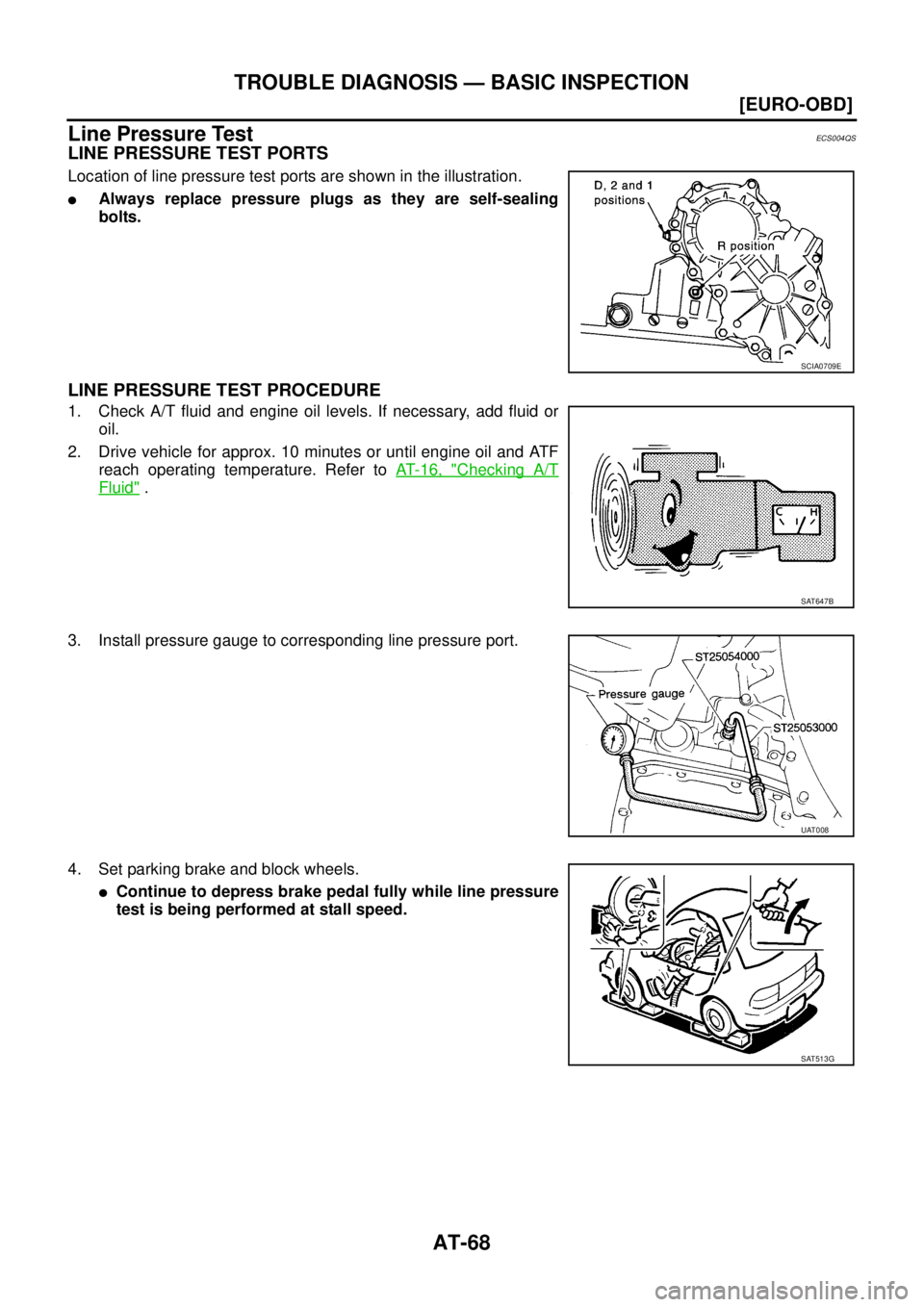
Line Pressure TestECS004QS
LINE PRESSURE TEST PORTS
Location of line pressure test ports are shown in the illustration.
�Always replace pressure plugs as they are self-sealing
bolts.
LINE PRESSURE TEST PROCEDURE
1. Check A/T fluid and engine oil levels. If necessary, add fluid or
oil.
2. Drive vehicle for approx. 10 minutes or until engine oil and ATF
reach operating temperature. Refer to AT- 1 6 , "
Checking A/T
Fluid" .
3. Install pressure gauge to corresponding line pressure port.
4. Set parking brake and block wheels.
�Continue to depress brake pedal fully while line pressure
test is being performed at stall speed.
SCIA0709E
SAT647B
UAT008
SAT513G
Page 2114 of 4179
AT-78
[EURO-OBD]
TROUBLE DIAGNOSIS — BASIC INSPECTION
Cruise Test — Part 1
1. CHECK STARTING GEAR (D1 ) POSITION
1. Drive vehicle for approximately 10 minutes to warm engine oil and ATF up to operating temperature.
2. Park vehicle on flat surface.
3. Set overdrive control switch to ON position.
4. Move selector lever to “P” position.
5. Start engine.
6. Move selector lever to “D” position.
7. Accelerate vehicle by constantly depressing accelerator pedal
half-way.
Read gear position. Refer to AT- 4 6 , "
DATA MONITOR
MODE (A/T)" .
Does vehicle start from D
1 ?
YES >> GO TO 2.
NO >>
�Mark the box on the “DIAGNOSTIC WORKSHEET”.
Refer to AT- 5 8
.
�GO TO AT- 2 1 4 , "Vehicle Cannot Be Started From D1"
.
�Continue “Road Test”. ATF operating temperature: 50 - 80°C (122 - 176°F)
SAT774B
SAT775B
SAT495G
Page 2128 of 4179
![NISSAN X-TRAIL 2003 Service Repair Manual AT-92
[EURO-OBD]
TROUBLE DIAGNOSIS — GENERAL DESCRIPTION
Does not change from “12 ” to “11 ”
in “1” position.ON vehicle1. PNP switchAT-100
2. Vehicle speed sensor·A/T (Revolution
se](/manual-img/5/57404/w960_57404-2127.png "NISSAN X-TRAIL 2003 Service Repair Manual AT-92
[EURO-OBD]
TROUBLE DIAGNOSIS — GENERAL DESCRIPTION
Does not change from “12 ” to “11 ”
in “1” position.ON vehicle1. PNP switchAT-100
2. Vehicle speed sensor·A/T (Revolution
se")
AT-92
[EURO-OBD]
TROUBLE DIAGNOSIS — GENERAL DESCRIPTION
Does not change from “12 ” to “11 ”
in “1” position.ON vehicle1. PNP switchAT-100
2. Vehicle speed sensor·A/T (Revolution
sensor) and vehicle speed sensor·MTRAT- 11 2, AT- 1 9 2
3. Shift solenoid valve AAT-161
4. Control valve assemblyAT-404
OFF vehicle5. Low one-way clutchAT-416
, AT- 4 2 3
6. Brake bandAT-497
7. Low & reverse brakeAT-483
Large shock changing from “12 ” to
“1
1 ” in “1” position.ON vehicle 1. Control valve assemblyAT-404OFF vehicle 2. Low & reverse brakeAT-483
Transmission overheats. ON vehicle1. Fluid levelAT- 6 4
2. Engine idling rpm EC-44
3. Accelerator pedal position (APP) sensorAT-173
4. Line pressure testAT- 6 8
5. Line pressure solenoid valveAT-154
6. Control valve assemblyAT-404
Transmission overheats. OFF vehicle7. Oil pumpAT-443
8. Reverse clutchAT-464
9. High clutchAT-469
10. Brake bandAT-497
11. Forward clutchAT-475
12. Overrun clutchAT-475
13. Low & reverse brakeAT-483
14. Torque converterAT-423
ATF shoots out during operation.
White smoke emitted from exhaust
pipe during operation.ON vehicle 1. Fluid levelAT- 6 4
OFF vehicle2. Reverse clutchAT-464
3. High clutchAT-469
4. Brake bandAT-497
5. Forward clutchAT-475
6. Overrun clutchAT-475
7. Low & reverse brakeAT-483
Offensive smell at fluid charging
pipe.ON vehicle 1. Fluid levelAT- 6 4
OFF vehicle2. Torque converterAT-423
3. Oil pumpAT-443
4. Reverse clutchAT-464
5. High clutchAT-469
6. Brake bandAT-497
7. Forward clutchAT-475
8. Overrun clutchAT-475
9. Low & reverse brakeAT-483
Symptom Condition Diagnostic Item Reference Page
Page 2132 of 4179
![NISSAN X-TRAIL 2003 Service Repair Manual AT-96
[EURO-OBD]
TROUBLE DIAGNOSIS — GENERAL DESCRIPTION
*1: These terminals are connected to the ECM.
*2: These terminals are connected to the data link connector.34 W/GPNP switch “D”
positi](/manual-img/5/57404/w960_57404-2131.png "NISSAN X-TRAIL 2003 Service Repair Manual AT-96
[EURO-OBD]
TROUBLE DIAGNOSIS — GENERAL DESCRIPTION
*1: These terminals are connected to the ECM.
*2: These terminals are connected to the data link connector.34 W/GPNP switch “D”
positi")
AT-96
[EURO-OBD]
TROUBLE DIAGNOSIS — GENERAL DESCRIPTION
*1: These terminals are connected to the ECM.
*2: These terminals are connected to the data link connector.34 W/GPNP switch “D”
position
and When setting selector lever to “D”
position.Battery voltage
When setting selector lever to other
positions.0V
35 Y/GPNP switch “R”
positionWhen setting selector lever to “R”
position.Battery voltage
When setting selector lever to other
positions.0V
36 GPNP switch “P”,
“N” positionWhen setting selector lever to “P”,
“N” position.Battery voltage
When setting selector lever to other
positions.0V
39 *1 L/OREngine speed sig-
nal
and Refer to EC-95
.—
40 L/BVehicle speed
sensorWhen moving vehicle at 2 to 3 km/h
(1 to 2 MPH) for 1 m (3 ft) or more.Voltage varies
between less
than 0V and
more than 4.5V
41 G/YAccelerator pedal
position (APP)
sensorWhen depressing accelerator pedal
slowly after warming up engine.
(Voltage rises gradually in response
to throttle position.)Fully-closed
throttle: 0.5V
Fully-open throt-
tle: 4V
42 B Sensor ground Always 0V
47 BRA/T fluid tempera-
ture sensorWhen ATF temperature is 20°C
(68°F).1.5V
When ATF temperature is 80°C
(176°F).0.5V
48 B Ground Always 0V Te r m i -
nal No.Wire color Item ConditionJudgementstan-
dard(Approx.)
Page 2142 of 4179
![NISSAN X-TRAIL 2003 Service Repair Manual AT-106
[EURO-OBD]
DTC P0710 A/T FLUID TEMPERATURE SENSOR CIRCUIT
DTC P0710 A/T FLUID TEMPERATURE SENSOR CIRCUITPFP:31940
DescriptionECS004R0
The A/T fluid temperature sensor detects the A/T fluid te](/manual-img/5/57404/w960_57404-2141.png "NISSAN X-TRAIL 2003 Service Repair Manual AT-106
[EURO-OBD]
DTC P0710 A/T FLUID TEMPERATURE SENSOR CIRCUIT
DTC P0710 A/T FLUID TEMPERATURE SENSOR CIRCUITPFP:31940
DescriptionECS004R0
The A/T fluid temperature sensor detects the A/T fluid te")
AT-106
[EURO-OBD]
DTC P0710 A/T FLUID TEMPERATURE SENSOR CIRCUIT
DTC P0710 A/T FLUID TEMPERATURE SENSOR CIRCUITPFP:31940
DescriptionECS004R0
The A/T fluid temperature sensor detects the A/T fluid temperature
and sends a signal to the TCM.
CONSULT-II REFERENCE VALUE IN DATA MONITOR MODE
Remarks: Specification data are reference values.
On Board Diagnosis LogicECS00CTJ
Possible CauseECS00CTK
Check the following items.
�Harness or connector
(The sensor circuit is open or shorted.)
�A/T fluid temperature sensor
DTC Confirmation ProcedureECS00CTL
CAUTION:
Always drive vehicle at a safe speed.
NOTE:
After the repair, perform the following procedure to confirm the malfunction is eliminated.
If “DTC Confirmation Procedure” has been previously conducted, always turn ignition switch “OFF”
and wait at least 5 seconds before conducting the next test.
SCIA0718E
SAT021J
Monitor item Condition Specification (Approximately)
A/T fluid temperature sensorCold [20°C (68°F)]
↓
Hot [80°C (176°F)]1.5V
↓
0.5V2.5 kΩ
↓
0.3 kΩ
Diagnostic trouble code Malfunction is detected when... Check items (Possible cause)
: ATF TEMP SEN/CIRC
TCM receives an excessively low or high
voltage from the sensor.
�Harness or connectors
(The sensor circuit is open or shorted.)
�A/T fluid temperature sensor
: P0710
Page 2145 of 4179
DTC P0710 A/T FLUID TEMPERATURE SENSOR CIRCUIT
AT-109
[EURO-OBD]
D
E
F
G
H
I
J
K
L
MA
B
AT
TERMINALS AND REFERENCE VALUE MEASURED BETWEEN EACH TERMINAL
Diagnostic ProcedureECS004R2
1. INSPECTION START
Do you have CONSULT-II?
YES or NO
YES >> GO TO 2.
NO >> GO TO 3.
2. CHECK INPUT SIGNAL OF A/T FLUID TEMPERATURE SENSOR (WITH CONSULT-II)
With CONSULT-II
1. Start engine.
2. Select “TCM INPUT SIGNALS” in “DATA MONITOR” mode for
“A/T” with CONSULT-II.
3. Read out the value of “FLUID TEMP SE”.
OK or NG
OK >> GO TO 4.
NG >> GO TO 5.
Termi-
nal No.Wire color Item ConditionJudgement stan-
dard
(Approx.)
42 B Sensor ground Always 0V
47 BRA/T fluid tempera-
ture sensorWhen ATF temperature is 20°C
(68°F).1.5V
When ATF temperature is 80°C
(176°F).0.5V
SAT014K
Vo l t a g e :
Cold [20°C (68°F)] → Hot [80°C (176°F)]
Approximately 1.5V → 0.5V
SAT614J
![NISSAN X-TRAIL 2003 Service Repair Manual AT-78
[EURO-OBD]
TROUBLE DIAGNOSIS — BASIC INSPECTION
Cruise Test — Part 1
1. CHECK STARTING GEAR (D1 ) POSITION
1. Drive vehicle for approximately 10 minutes to warm engine oil and ATF up to op](/manual-img/5/57404/w960_57404-2113.png "NISSAN X-TRAIL 2003 Service Repair Manual AT-78
[EURO-OBD]
TROUBLE DIAGNOSIS — BASIC INSPECTION
Cruise Test — Part 1
1. CHECK STARTING GEAR (D1 ) POSITION
1. Drive vehicle for approximately 10 minutes to warm engine oil and ATF up to op")
![NISSAN X-TRAIL 2003 Service Repair Manual DTC P0710 A/T FLUID TEMPERATURE SENSOR CIRCUIT
AT-109
[EURO-OBD]
D
E
F
G
H
I
J
K
L
MA
B
AT
TERMINALS AND REFERENCE VALUE MEASURED BETWEEN EACH TERMINAL
Diagnostic ProcedureECS004R2
1. INSPECTION ST](/manual-img/5/57404/w960_57404-2144.png "NISSAN X-TRAIL 2003 Service Repair Manual DTC P0710 A/T FLUID TEMPERATURE SENSOR CIRCUIT
AT-109
[EURO-OBD]
D
E
F
G
H
I
J
K
L
MA
B
AT
TERMINALS AND REFERENCE VALUE MEASURED BETWEEN EACH TERMINAL
Diagnostic ProcedureECS004R2
1. INSPECTION ST")