Page 1466 of 4179
![NISSAN X-TRAIL 2003 Service Repair Manual EC-1088
[YD (WITH EURO-OBD)]
DTC P0563 BATTERY VOLTAGE
3. CHECK JUMPER CABLES INSTALLATION
Check that the jumper cables are connected in the correct sequence.
OK or NG
OK >> GO TO 4.
NG >> Reconnect NISSAN X-TRAIL 2003 Service Repair Manual EC-1088
[YD (WITH EURO-OBD)]
DTC P0563 BATTERY VOLTAGE
3. CHECK JUMPER CABLES INSTALLATION
Check that the jumper cables are connected in the correct sequence.
OK or NG
OK >> GO TO 4.
NG >> Reconnect](/manual-img/5/57404/w960_57404-1465.png)
EC-1088
[YD (WITH EURO-OBD)]
DTC P0563 BATTERY VOLTAGE
3. CHECK JUMPER CABLES INSTALLATION
Check that the jumper cables are connected in the correct sequence.
OK or NG
OK >> GO TO 4.
NG >> Reconnect jumper cables properly.
4. CHECK BATTERY FOR BOOSTER
Check that the battery for the booster is a 12V battery.
OK or NG
OK >> GO TO 5.
NG >> Change the vehicle for booster.
5. PERFORM DTC CONFIRMATION PROCEDURE AGAIN
Perform EC-1087, "
DTC Confirmation Procedure" , again.
OK or NG
OK >> GO TO 7.
NG >> GO TO 6.
6. REPLACE ECM
1. Replace ECM.
2. Perform initialization of NATS system and registration of all NATS ignition key IDs. Refer to EC-896,
"NATS (Nissan Anti-theft System)" .
3. Perform Fuel Pump Learning Value Clearing. Refer to EC-890, "
Fuel Pump Learning Value Clearing" .
>>INSPECTION END
7. CHECK ELECTRICAL PARTS DAMAGE
Check the following for damage.
�Wiring harness and harness connectors for burn
�Fuses for short
OK or NG
OK >>INSPECTION END
NG >> Repair or replace malfunctioning part.
SEF439Z
Page 1755 of 4179
![NISSAN X-TRAIL 2003 Service Repair Manual DTC P0563 BATTERY VOLTAGE
EC-1377
[YD (WITHOUT EURO-OBD)]
C
D
E
F
G
H
I
J
K
L
MA
EC
3. CHECK JUMPER CABLES INSTALLATION
Check that the jumper cables are connected in the correct sequence.
OK or NG
O NISSAN X-TRAIL 2003 Service Repair Manual DTC P0563 BATTERY VOLTAGE
EC-1377
[YD (WITHOUT EURO-OBD)]
C
D
E
F
G
H
I
J
K
L
MA
EC
3. CHECK JUMPER CABLES INSTALLATION
Check that the jumper cables are connected in the correct sequence.
OK or NG
O](/manual-img/5/57404/w960_57404-1754.png)
DTC P0563 BATTERY VOLTAGE
EC-1377
[YD (WITHOUT EURO-OBD)]
C
D
E
F
G
H
I
J
K
L
MA
EC
3. CHECK JUMPER CABLES INSTALLATION
Check that the jumper cables are connected in the correct sequence.
OK or NG
OK >> GO TO 4.
NG >> Reconnect jumper cables properly.
4. CHECK BATTERY FOR BOOSTER
Check that the battery for the booster is a 12V battery.
OK or NG
OK >> GO TO 5.
NG >> Change the vehicle for booster.
5. PERFORM DTC CONFIRMATION PROCEDURE AGAIN
Perform EC-1376, "
DTC Confirmation Procedure" , again.
OK or NG
OK >> GO TO 7.
NG >> GO TO 6.
6. REPLACE ECM
1. Replace ECM.
2. Perform initialization of NATS system and registration of all NATS ignition key IDs. Refer to EC-1224,
"NATS (Nissan Anti-theft System)" .
3. Perform Fuel Pump Learning Value Clearing. Refer to EC-1221, "
Fuel Pump Learning Value Clearing" .
>>INSPECTION END
7. CHECK ELECTRICAL PARTS DAMAGE
Check the following for damage.
�Wiring harness and harness connectors for burn
�Fuses for short
OK or NG
OK >>INSPECTION END
NG >> Repair or replace malfunctioning part.
SEF439Z
Page 3464 of 4179
ATC-68
TROUBLE DIAGNOSIS
Potentio Temperature Control (PTC)
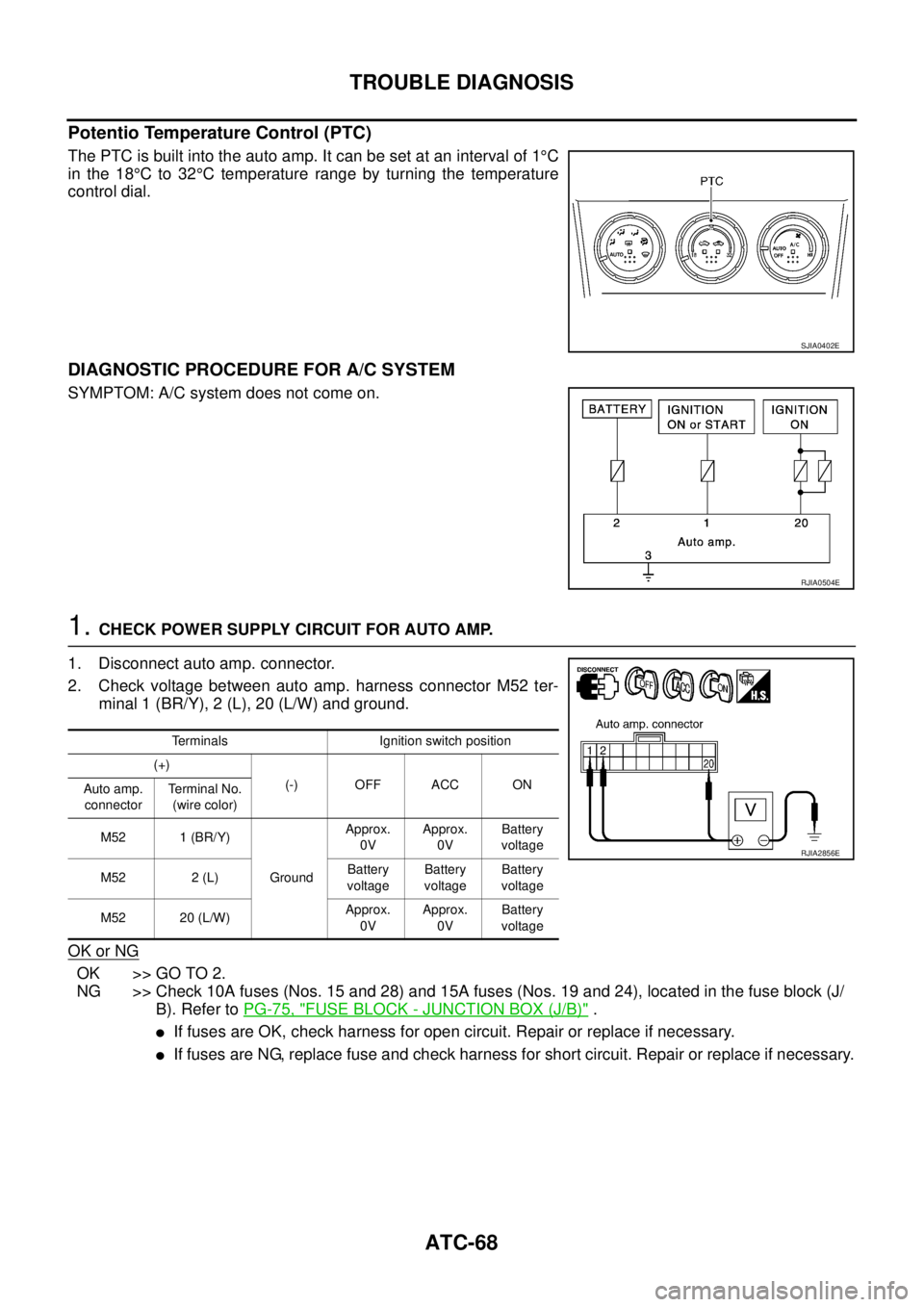
The PTC is built into the auto amp. It can be set at an interval of 1°C
in the 18°C to 32°C temperature range by turning the temperature
control dial.
DIAGNOSTIC PROCEDURE FOR A/C SYSTEM
SYMPTOM: A/C system does not come on.
1. CHECK POWER SUPPLY CIRCUIT FOR AUTO AMP.
1. Disconnect auto amp. connector.
2. Check voltage between auto amp. harness connector M52 ter-
minal 1 (BR/Y), 2 (L), 20 (L/W) and ground.
OK or NG
OK >> GO TO 2.
NG >> Check 10A fuses (Nos. 15 and 28) and 15A fuses (Nos. 19 and 24), located in the fuse block (J/
B). Refer to PG-75, "
FUSE BLOCK - JUNCTION BOX (J/B)" .
�If fuses are OK, check harness for open circuit. Repair or replace if necessary.
�If fuses are NG, replace fuse and check harness for short circuit. Repair or replace if necessary.
SJIA0402E
RJIA0504E
Terminals Ignition switch position
(+)
(-) OFF ACC ON
Auto amp.
connectorTe r m i n a l N o .
(wire color)
M52 1 (BR/Y)
GroundApprox.
0VApprox.
0VBattery
voltage
M52 2 (L)Battery
voltageBattery
voltageBattery
voltage
M52 20 (L/W)Approx.
0VApprox.
0VBattery
voltage
RJIA2856E
Page 3481 of 4179
TROUBLE DIAGNOSIS
ATC-85
C
D
E
F
G
H
I
K
L
MA
B
AT C
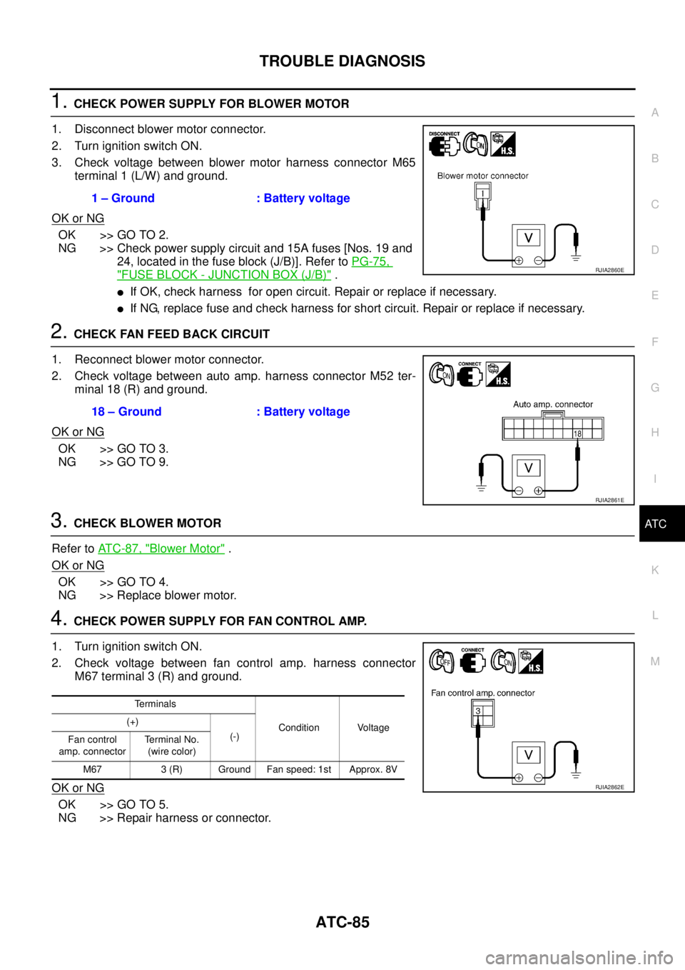
1. CHECK POWER SUPPLY FOR BLOWER MOTOR
1. Disconnect blower motor connector.
2. Turn ignition switch ON.
3. Check voltage between blower motor harness connector M65
terminal 1 (L/W) and ground.
OK or NG
OK >> GO TO 2.
NG >> Check power supply circuit and 15A fuses [Nos. 19 and
24, located in the fuse block (J/B)]. Refer to PG-75,
"FUSE BLOCK - JUNCTION BOX (J/B)" .
�If OK, check harness for open circuit. Repair or replace if necessary.
�If NG, replace fuse and check harness for short circuit. Repair or replace if necessary.
2. CHECK FAN FEED BACK CIRCUIT
1. Reconnect blower motor connector.
2. Check voltage between auto amp. harness connector M52 ter-
minal 18 (R) and ground.
OK or NG
OK >> GO TO 3.
NG >> GO TO 9.
3. CHECK BLOWER MOTOR
Refer to AT C - 8 7 , "
Blower Motor" .
OK or NG
OK >> GO TO 4.
NG >> Replace blower motor.
4. CHECK POWER SUPPLY FOR FAN CONTROL AMP.
1. Turn ignition switch ON.
2. Check voltage between fan control amp. harness connector
M67 terminal 3 (R) and ground.
OK or NG
OK >> GO TO 5.
NG >> Repair harness or connector.1 – Ground : Battery voltage
RJIA2860E
18 – Ground : Battery voltage
RJIA2861E
Terminals
Condition Voltage (+)
(-)
Fan control
amp. connectorTerminal No.
(wire color)
M67 3 (R) Ground Fan speed: 1st Approx. 8V
RJIA2862E
Page 3624 of 4179
MTC-16
TROUBLE DIAGNOSIS
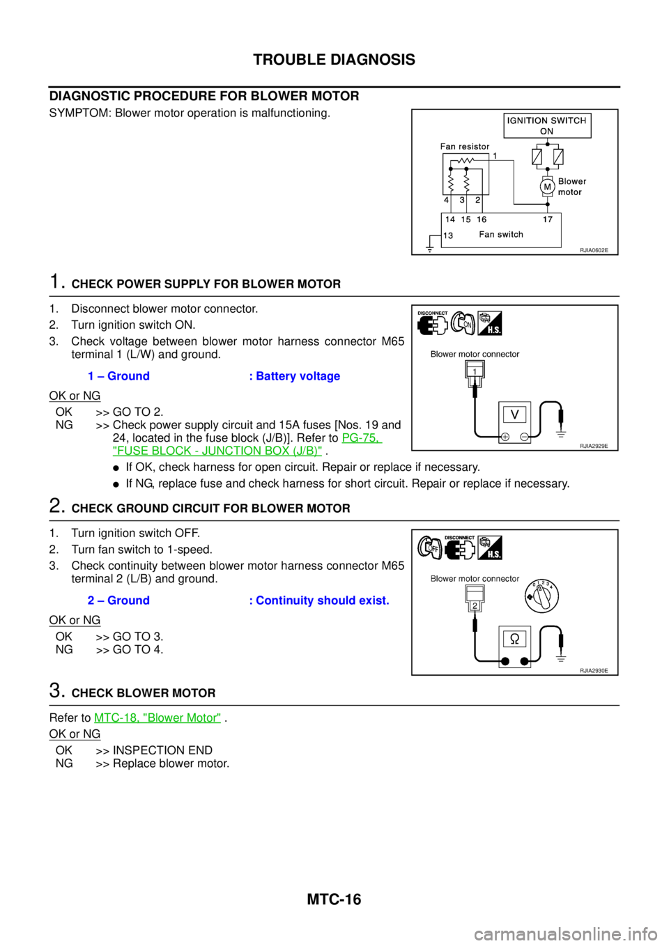
DIAGNOSTIC PROCEDURE FOR BLOWER MOTOR
SYMPTOM: Blower motor operation is malfunctioning.
1. CHECK POWER SUPPLY FOR BLOWER MOTOR
1. Disconnect blower motor connector.
2. Turn ignition switch ON.
3. Check voltage between blower motor harness connector M65
terminal 1 (L/W) and ground.
OK or NG
OK >> GO TO 2.
NG >> Check power supply circuit and 15A fuses [Nos. 19 and
24, located in the fuse block (J/B)]. Refer to PG-75,
"FUSE BLOCK - JUNCTION BOX (J/B)" .
�If OK, check harness for open circuit. Repair or replace if necessary.
�If NG, replace fuse and check harness for short circuit. Repair or replace if necessary.
2. CHECK GROUND CIRCUIT FOR BLOWER MOTOR
1. Turn ignition switch OFF.
2. Turn fan switch to 1-speed.
3. Check continuity between blower motor harness connector M65
terminal 2 (L/B) and ground.
OK or NG
OK >> GO TO 3.
NG >> GO TO 4.
3. CHECK BLOWER MOTOR
Refer to MTC-18, "
Blower Motor" .
OK or NG
OK >> INSPECTION END
NG >> Replace blower motor.
RJIA0602E
1 – Ground : Battery voltage
RJIA2929E
2 – Ground : Continuity should exist.
RJIA2930E
Page 3699 of 4179
COMBINATION METERS
DI-21
C
D
E
F
G
H
I
J
L
MA
B
DI
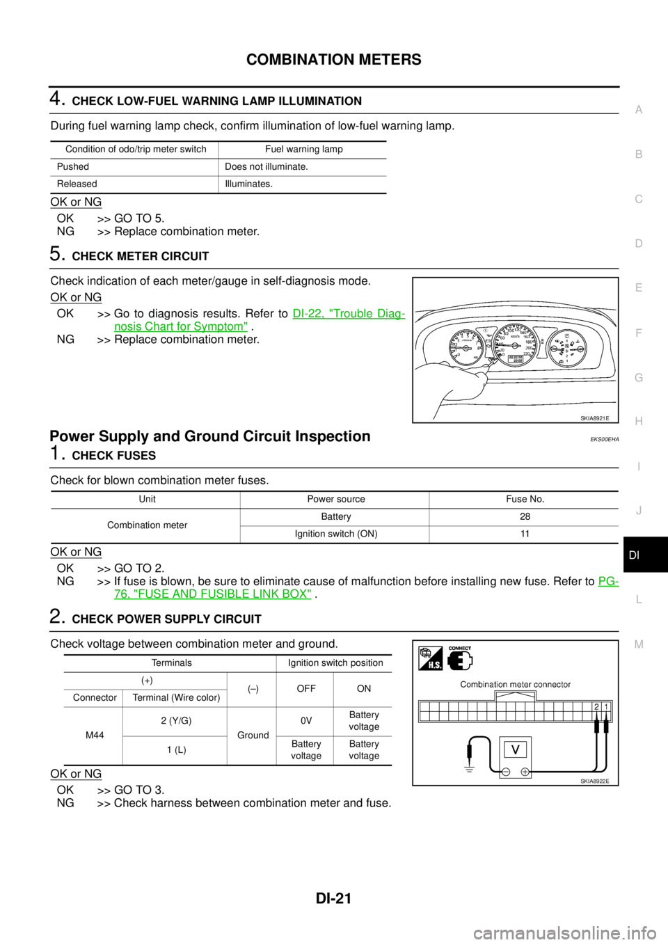
4. CHECK LOW-FUEL WARNING LAMP ILLUMINATION
During fuel warning lamp check, confirm illumination of low-fuel warning lamp.
OK or NG
OK >> GO TO 5.
NG >> Replace combination meter.
5. CHECK METER CIRCUIT
Check indication of each meter/gauge in self-diagnosis mode.
OK or NG
OK >> Go to diagnosis results. Refer to DI-22, "Trouble Diag-
nosis Chart for Symptom" .
NG >> Replace combination meter.
Power Supply and Ground Circuit InspectionEKS00EHA
1. CHECK FUSES
Check for blown combination meter fuses.
OK or NG
OK >> GO TO 2.
NG >> If fuse is blown, be sure to eliminate cause of malfunction before installing new fuse. Refer to PG-
76, "FUSE AND FUSIBLE LINK BOX" .
2. CHECK POWER SUPPLY CIRCUIT
Check voltage between combination meter and ground.
OK or NG
OK >> GO TO 3.
NG >> Check harness between combination meter and fuse.
Condition of odo/trip meter switch Fuel warning lamp
Pushed Does not illuminate.
Released Illuminates.
SKIA8921E
Unit Power source Fuse No.
Combination meterBattery 28
Ignition switch (ON) 11
Terminals Ignition switch position
(+)
(–) OFF ON
Connector Terminal (Wire color)
M442 (Y/G)
Ground0VBattery
voltage
1 (L)Battery
voltageBattery
voltage
SKIA8922E
Page 3736 of 4179
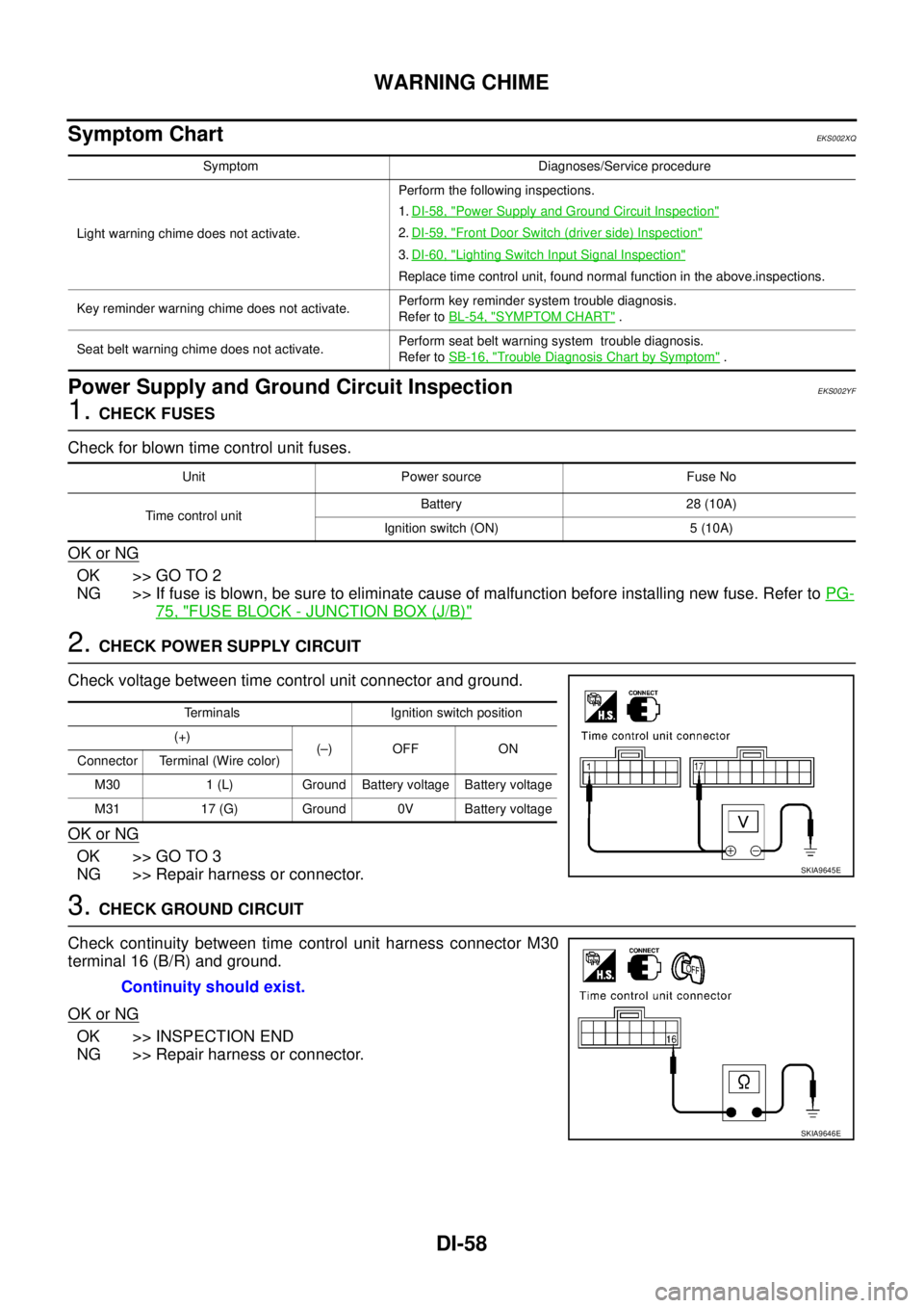
DI-58
WARNING CHIME
Symptom ChartEKS002XQ
Power Supply and Ground Circuit InspectionEKS002YF
1. CHECK FUSES
Check for blown time control unit fuses.
OK or NG
OK >> GO TO 2
NG >> If fuse is blown, be sure to eliminate cause of malfunction before installing new fuse. Refer to PG-
75, "FUSE BLOCK - JUNCTION BOX (J/B)"
2. CHECK POWER SUPPLY CIRCUIT
Check voltage between time control unit connector and ground.
OK or NG
OK >> GO TO 3
NG >> Repair harness or connector.
3. CHECK GROUND CIRCUIT
Check continuity between time control unit harness connector M30
terminal 16 (B/R) and ground.
OK or NG
OK >> INSPECTION END
NG >> Repair harness or connector.
Symptom Diagnoses/Service procedure
Light warning chime does not activate.Perform the following inspections.
1.DI-58, "
Power Supply and Ground Circuit Inspection"
2.DI-59, "Front Door Switch (driver side) Inspection"
3.DI-60, "Lighting Switch Input Signal Inspection"
Replace time control unit, found normal function in the above.inspections.
Key reminder warning chime does not activate. Perform key reminder system trouble diagnosis.
Refer to BL-54, "
SYMPTOM CHART" .
Seat belt warning chime does not activate.Perform seat belt warning system trouble diagnosis.
Refer to SB-16, "
Trouble Diagnosis Chart by Symptom" .
Unit Power source Fuse No
Time control unitBattery 28 (10A)
Ignition switch (ON) 5 (10A)
Terminals Ignition switch position
(+)
(–) OFF ON
Connector Terminal (Wire color)
M30 1 (L) Ground Battery voltage Battery voltage
M31 17 (G) Ground 0V Battery voltage
SKIA9645E
Continuity should exist.
SKIA9646E
Page 3972 of 4179

AV-82
NAVIGATION SYSTEM
Power Supply and Ground Circuit Check for NAVI control unitEKS00F35
1. CHECK FUSE
Check that the following fuses of the NAVI control unit are not blown.
OK or NG
OK >> GO TO 2.
NG >> If fuse is blown, be sure to eliminate cause of problem before installing new fuse. Refer toPG-2,
"POWER SUPPLY ROUTING" .
2. POWER SUPPLY CIRCUIT CHECK
Check voltage between NAVI control unit and ground.
OK or NG
OK >> GO TO 3.
NG >> Repair or replace harness.
3. GROUND CIRCUIT CHECK
1. Turn ignition switch OFF.
2. Disconnect NAVI control unit connector.
3. Check continuity between NAVI control unit and ground.
OK or NG
OK >> INSPECTION END.
NG >> Repair or replace harness.
Te r m i n a l s
Power source Fuse No.
Connector Terminal (wire color)
NAVI control unit
M1162 (Y/G)
Battery 32
3 (Y/G)
6 (GY/L) Ignition switch ACC or ON 4
Terminals
OFF ACC ON (+)
(-)
ConnectorTerminal
(wire color)
NAVI control
unit
M1162 (Y/G)
GroundBattery
voltageBattery
voltageBattery
voltage
3 (Y/G)Battery
voltageBattery
voltageBattery
voltage
6 (GY/L) 0VBattery
voltageBattery
voltage
SKIA8719E
Terminals
Continuity (+)
(-)
Connector Terminal (wire color)
NAVI control unit
M1161 (B/R)
Ground Yes
4 (B/R)
SKIA8720E