Page 2059 of 4179

OVERALL SYSTEM
AT-23
D
E
F
G
H
I
J
K
L
MA
B
AT
CLUTCH AND BAND CHART
�*1: Operates when overdrive control switch is set in “OFF” position.
�*2: Oil pressure is applied to both 2nd “apply” side and 3rd “release” side of band servo piston. However, brake band does not con-
tract because oil pressure area on the “release” side is greater than that on the “apply” side.
�*3: Oil pressure is applied to 4th “apply” side in condition *2 above, and brake band contracts.
�*4: A/T will not shift to 4th when overdrive control switch is set in “OFF” position.
�: Operates.
�A: Operates when throttle opening is less than 3/16, activating engine brake.
�B: Operates during “progressive” acceleration.
�C: Operates but does not affect power transmission.
�D: Operates when throttle opening is less than 3/16, but does not affect engine brake. Shift positionRever
se
clutch
5High
clutch
6For-
ward
clutch
15Over-
run
clutch
17Band servo
Forward
one-way
clutch
16Low
one-
way
clutch
18Low &
revers
e
brake
19Lock-
upRemarks
2nd
apply3rd
releas
e4th
apply
PPA R K
POSITION
RREVERSE
POSITION
NNEUTRAL
POSITION
D*41st *1D B B
Automatic
shift
1 ⇔ 2 ⇔ 3 ⇔
4 2nd *1A B
3rd *1A *2C C B
*1
4th C *3C C
21stBB
Automatic
shift
1 ⇔ 2⇐3 2ndB
3rd *2C C B
11stB
Locks (held
stationary) in
1st speed
1 ⇐ 2⇐3 2ndB
3rd *2C C B
Page 2061 of 4179
OVERALL SYSTEM
AT-25
D
E
F
G
H
I
J
K
L
MA
B
AT
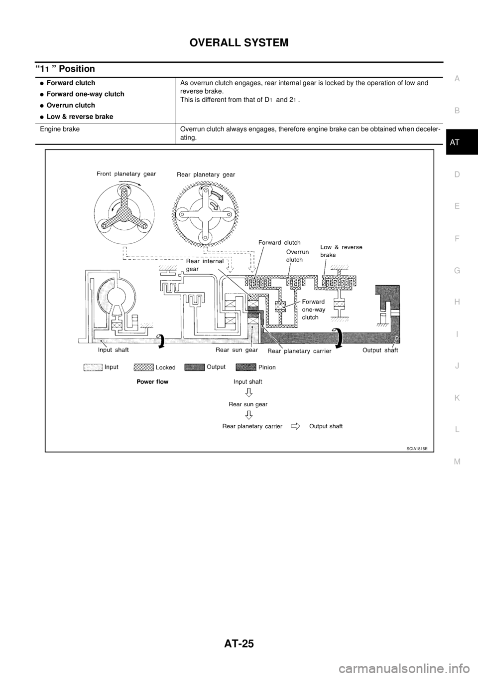
“11 ” Position
�Forward clutch
�Forward one-way clutch
�Overrun clutch
�Low & reverse brakeAs overrun clutch engages, rear internal gear is locked by the operation of low and
reverse brake.
This is different from that of D
1 and 21 .
Engine brake Overrun clutch always engages, therefore engine brake can be obtained when deceler-
ating.
SCIA1816E
Page 2062 of 4179
AT-26
OVERALL SYSTEM
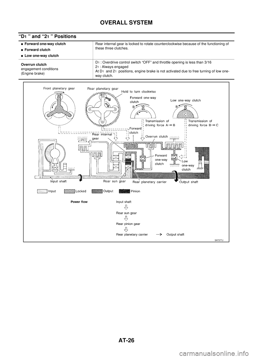
“D1 ” and “21 ” Positions
�Forward one-way clutch
�Forward clutch
�Low one-way clutchRear internal gear is locked to rotate counterclockwise because of the functioning of
these three clutches.
Overrun clutch
engagement conditions
(Engine brake)D
1 : Overdrive control switch “OFF” and throttle opening is less than 3/16
2
1 : Always engaged
At D
1 and 21 positions, engine brake is not activated due to free turning of low one-
way clutch.
SAT377J
Page 2065 of 4179
OVERALL SYSTEM
AT-29
D
E
F
G
H
I
J
K
L
MA
B
AT
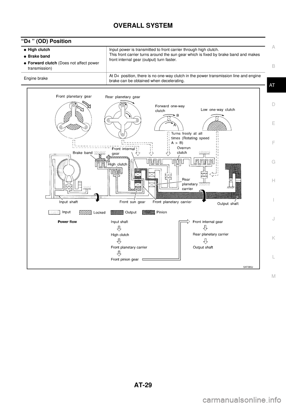
“D4 ” (OD) Position
�High clutch
�Brake band
�Forward clutch (Does not affect power
transmission)Input power is transmitted to front carrier through high clutch.
This front carrier turns around the sun gear which is fixed by brake band and makes
front internal gear (output) turn faster.
Engine brakeAt D
4 position, there is no one-way clutch in the power transmission line and engine
brake can be obtained when decelerating.
SAT380J
Page 2066 of 4179
AT-30
OVERALL SYSTEM
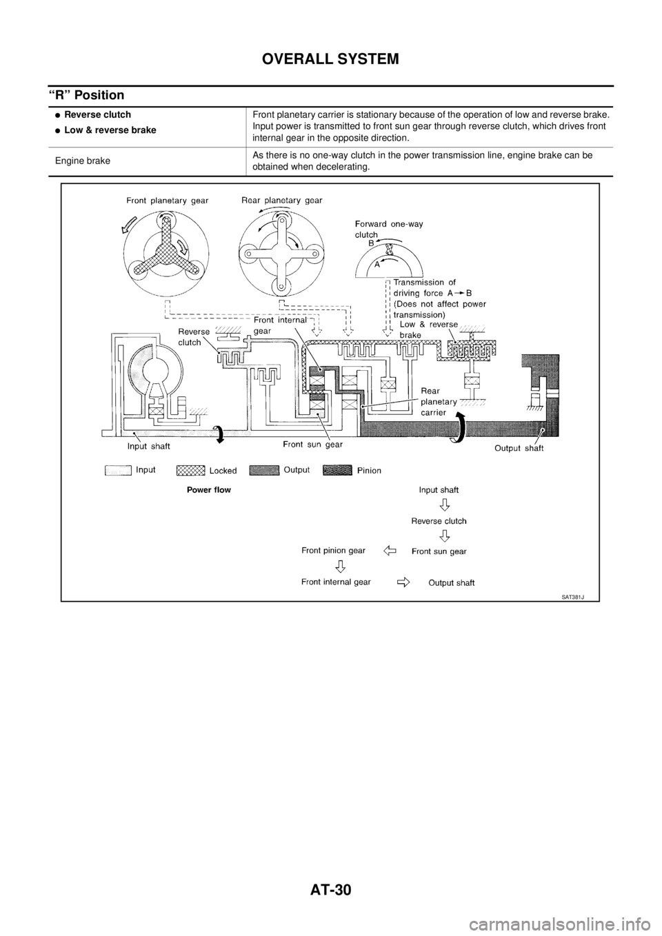
“R” Position
�Reverse clutch
�Low & reverse brakeFront planetary carrier is stationary because of the operation of low and reverse brake.
Input power is transmitted to front sun gear through reverse clutch, which drives front
internal gear in the opposite direction.
Engine brakeAs there is no one-way clutch in the power transmission line, engine brake can be
obtained when decelerating.
SAT381J
Page 2067 of 4179

OVERALL SYSTEM
AT-31
D
E
F
G
H
I
J
K
L
MA
B
AT
TCM FunctionECS004QE
The function of the TCM is to:
�Receive input signals sent from various switches and sensors.
�Determine required line pressure, shifting point, lock-up operation, and engine brake operation.
�Send required output signals to the respective solenoids.
CONTROL SYSTEM OUTLINE
The automatic transaxle senses vehicle operating conditions through various switches and sensors. It always
controls the optimum shift position and reduces shifting and lock-up shocks.
CONTROL SYSTEM
SWITCHES & SENSORS
�TCM
�ACTUATORS
PNP switch
Accelerator pedal position (APP)
sensor
Closed throttle position signal
Wide open throttle position signal
Engine speed signal
A/T fluid temperature sensor
Revolution sensor
Vehicle speed sensor
Overdrive control switch signal
Stop lamp switch signalShift control
Line pressure control
Lock-up control
Overrun clutch control
Timing control
Fail-safe control
Self-diagnosis
CONSULT-II communication line
control
CAN systemShift solenoid valve A
Shift solenoid valve B
Overrun clutch solenoid valve
Torque converter clutch solenoid
valve
Line pressure solenoid valve
O/D OFF indicator lamp
SCIA4505E
Page 2068 of 4179
 is a serial communication line for real time application. It is an on-vehicle mul-
tiplex communicatio")
AT-32
OVERALL SYSTEM
CAN CommunicationECS00CTB
SYSTEM DESCRIPTION
CAN (Controller Area Network) is a serial communication line for real time application. It is an on-vehicle mul-
tiplex communication line with high data communication speed and excellent error detection ability. Many elec-
tronic control units are equipped onto a vehicle, and each control unit shares information and links with other
control units during operation (not independent). In CAN communication, control units are connected with 2
communication lines (CAN H line, CAN L line) allowing a high rate of information transmission with less wiring.
Each control unit transmits/receives data but selectively reads required data only.
ABS MODELS
System diagram
Input/output signal chart
T: Transmit R: Receive
PKIA6457E
Signals TCM ECM Combination meter
Stop lamp switch signal R T
P·N range signal R T
A/T position indicator lamp signal T R
Overdrive control switch signal R T
O/D OFF indicator signal T R
Closed throttle position signal R T
Wide open throttle position signal R T
Output shaft revolution signal T R
Engine A/T integrated control signalRT
TR
A/T self-diagnosis signal T R
Page 2069 of 4179
OVERALL SYSTEM
AT-33
D
E
F
G
H
I
J
K
L
MA
B
AT
ESP MODELS
System diagram
Input/output signal chart
T: Transmit R: Receive
PKIA6460E
Signals TCM ECM Combination meter
Stop lamp switch signal R T
P·N range signal R T
A/T position indicator lamp signal T R
O/D OFF indicator signal T R
Overdrive control switch signal R T
Closed throttle position signal R T
Wide open throttle position signal R T
Output shaft revolution signal T R
Engine and A/T integratedRT
TR
A/T self-diagnosis signal R T