Page 1911 of 4179
ACC-1
ACCELERATOR CONTROL SYSTEM
B ENGINE
CONTENTS
C
D
E
F
G
H
I
J
K
L
M
SECTION
A
ACC
ACCELERATOR CONTROL SYSTEM
ACCELERATOR CONTROL SYSTEM ...................... 2
Removal and Installation .......................................... 2
REMOVAL ............................................................. 2
INSTALLATION ..................................................... 2
INSPECTION AFTER INSTALLATION ................. 2SERVICE DATA AND SPECIFICATIONS (SDS) ........ 3
Tightening Torque ..................................................... 3
Page 1917 of 4179
PREPARATION
CL-3
D
E
F
G
H
I
J
K
L
MA
B
CL
PREPARATIONPFP:00002
Special Service ToolsECS008B7
Commercial Service ToolsECS00CRA
Tool number
Tool nameDescription
ST20050240
Diaphragm adjusting wrenchAdjusting unevenness of diaphragm spring of
clutch cover
KV30101600
Clutch aligning bar
a: 15.9 mm (0.626 in) dia.
b: 17.9 mm (0.705 in) dia.
c: 40 mm (1.57 in) dia.Installing clutch cover and clutch disc
(QR engine model)
ST20630000
Clutch aligning bar
a: 15.8 mm (0.622 in) dia.
b: 22.9 mm (0.902 in) dia.
c: 45.0 mm (1.077 in)Installing clutch cover and clutch disc
(YD engine model)
ZZA0508D
S-NT405
S-NT405
Tool nameDescription
Pin punch
Tip diameter: 4.5 mm (0.177 in) dia.Removing and installing master cylinder
spring pin
GG94310000
Flare nut torque wrench
a: 10 mm (0.39 in)Removing and installing clutch piping
ZZA0515D
S-NT406
Page 1918 of 4179

CL-4
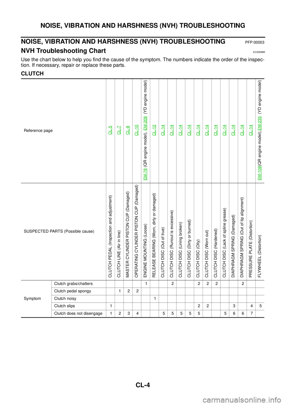
NOISE, VIBRATION AND HARSHNESS (NVH) TROUBLESHOOTING
NOISE, VIBRATION AND HARSHNESS (NVH) TROUBLESHOOTINGPFP:00003
NVH Troubleshooting ChartECS008B8
Use the chart below to help you find the cause of the symptom. The numbers indicate the order of the inspec-
tion. If necessary, repair or replace these parts.
CLUTCH
Reference pageCL-5CL-7CL-8CL-10
EM-78
(QR engine model), EM-208
(YD engine model)
CL-12
CL-14CL-14CL-14CL-14CL-14CL-14CL-14CL-14CL-14CL-14CL-14
EM-108
(QR engine model),EM-235
(YD engine model)
SUSPECTED PARTS (Possible cause)
CLUTCH PEDAL (Inspection and adjustment)
CLUTCH LINE (Air in line)
MASTER CYLINDER PISTON CUP (Damaged)
OPERATING CYLINDER PISTON CUP (Damaged)
ENGINE MOUNTING (Loose)
RELEASE BEARING (Worn, dirty or damaged)
CLUTCH DISC (Out of true)
CLUTCH DISC (Runout is excessive)
CLUTCH DISC (Lining broken)
CLUTCH DISC (Dirty or burned)
CLUTCH DISC (Oily)
CLUTCH DISC (Worn out)
CLUTCH DISC (Hardened)
CLUTCH DISC (Lack of spline grease)
DIAPHRAGM SPRING (Damaged)
DIAPHRAGM SPRING (Out of tip alignment)
PRESSURE PLATE (Distortion)
FLYWHEEL (Distortion)
SymptomClutch grabs/chatters 1 2 2 2 2 2
Clutch pedal spongy 1 2 2
Clutch noisy 1
Clutch slips 1 2 2 3 4 5
Clutch does not disengage 1 2 3 4 5 5 5 5 5 5 6 6 7
Page 1928 of 4179
CL-14
CLUTCH DISC, CLUTCH COVER AND FLYWHEEL
CLUTCH DISC, CLUTCH COVER AND FLYWHEELPFP:30100
Removal and InstallationECS008BG
—QR engine model—
—YD engine model—
CAUTION:
Be careful not to bring any grease into contact with the clutch disc facing, pressure plate surface, or
flywheel surface.
REMOVAL
1. Remove manual transaxle from the vehicle. Refer to MT-17, "Removal and Installation"
2. Loosen clutch cover mounting bolts evenly. Remove clutch cover and clutch disc.
PCIB0768E
1. Flywheel 2. Clutch disc 3. Clutch cover
PCIB0769E
1. Flywheel 2. Clutch disc 3. Clutch cover
Page 1929 of 4179

CLUTCH DISC, CLUTCH COVER AND FLYWHEEL
CL-15
D
E
F
G
H
I
J
K
L
MA
B
CL
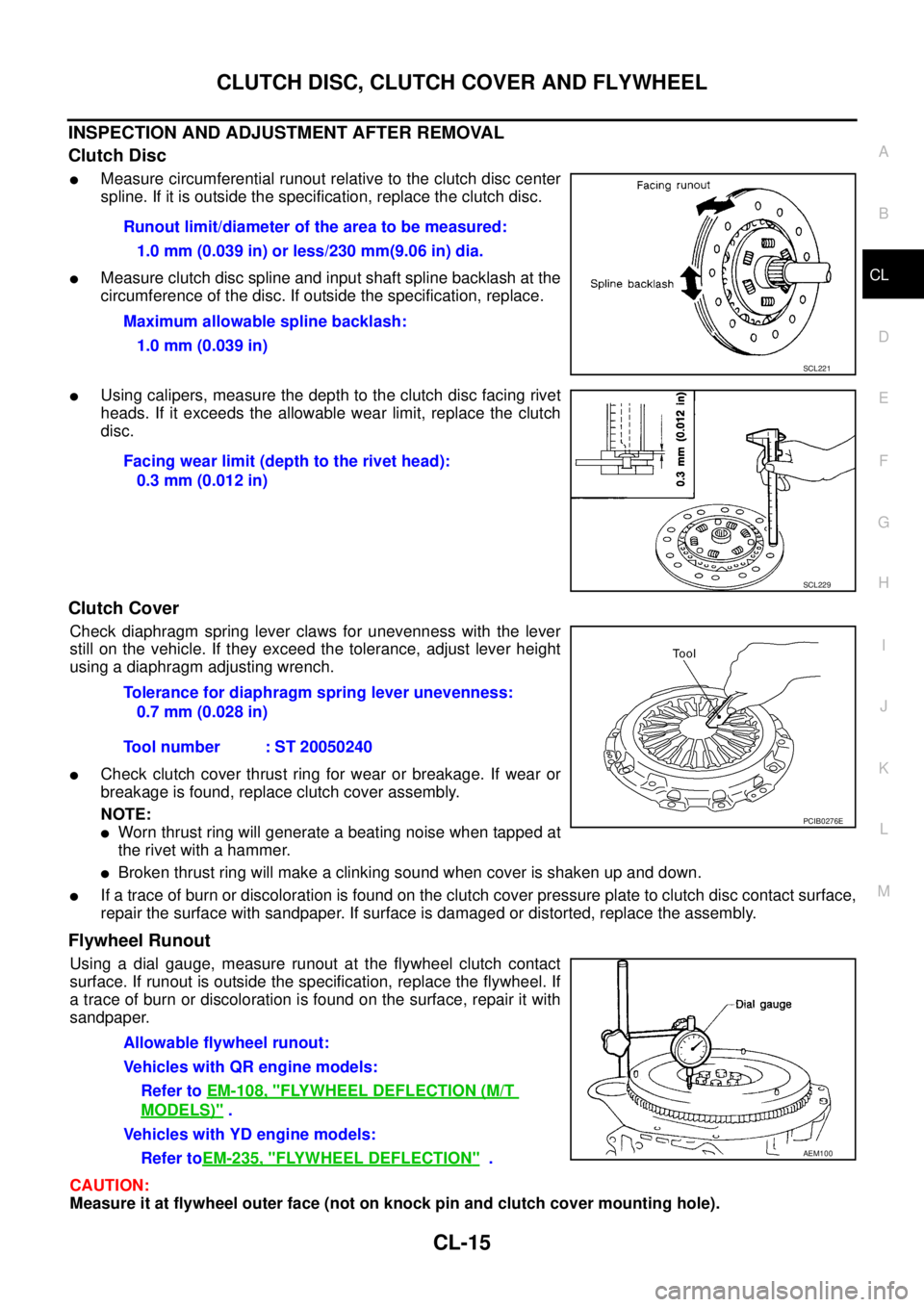
INSPECTION AND ADJUSTMENT AFTER REMOVAL
Clutch Disc
�Measure circumferential runout relative to the clutch disc center
spline. If it is outside the specification, replace the clutch disc.
�Measure clutch disc spline and input shaft spline backlash at the
circumference of the disc. If outside the specification, replace.
�Using calipers, measure the depth to the clutch disc facing rivet
heads. If it exceeds the allowable wear limit, replace the clutch
disc.
Clutch Cover
Check diaphragm spring lever claws for unevenness with the lever
still on the vehicle. If they exceed the tolerance, adjust lever height
using a diaphragm adjusting wrench.
�Check clutch cover thrust ring for wear or breakage. If wear or
breakage is found, replace clutch cover assembly.
NOTE:
�Worn thrust ring will generate a beating noise when tapped at
the rivet with a hammer.
�Broken thrust ring will make a clinking sound when cover is shaken up and down.
�If a trace of burn or discoloration is found on the clutch cover pressure plate to clutch disc contact surface,
repair the surface with sandpaper. If surface is damaged or distorted, replace the assembly.
Flywheel Runout
Using a dial gauge, measure runout at the flywheel clutch contact
surface. If runout is outside the specification, replace the flywheel. If
a trace of burn or discoloration is found on the surface, repair it with
sandpaper.
CAUTION:
Measure it at flywheel outer face (not on knock pin and clutch cover mounting hole).Runout limit/diameter of the area to be measured:
1.0 mm (0.039 in) or less/230 mm(9.06 in) dia.
Maximum allowable spline backlash:
1.0 mm (0.039 in)
SCL221
Facing wear limit (depth to the rivet head):
0.3 mm (0.012 in)
SCL229
Tolerance for diaphragm spring lever unevenness:
0.7 mm (0.028 in)
Tool number : ST 20050240
PCIB0276E
Allowable flywheel runout:
Vehicles with QR engine models:
Refer to EM-108, "
FLYWHEEL DEFLECTION (M/T
MODELS)" .
Vehicles with YD engine models:
Refer toEM-235, "
FLYWHEEL DEFLECTION" .AEM100
Page 1930 of 4179
CL-16
CLUTCH DISC, CLUTCH COVER AND FLYWHEEL
INSTALLATION
1. Apply recommended grease to clutch disc and input shaft splines.
CAUTION:
Be sure to apply grease to the points specified. Otherwise, noise, poor disengagement, or damage
to the clutch may result. Excessive grease may cause slip or quiver. Wipe off any grease oozing
from the parts.
2. Install clutch disc and clutch cover. Pre-tighten mounting bolts
and install clutch aligning bar.
3. Tighten clutch cover attaching bolts evenly in two steps in the
order shown in the figure. Refer to CL-14, "
Removal and Instal-
lation" .
4. Install manual transaxle. Refer to MT-17, "
Removal and Installa-
tion" .
Engine type Tool number
QR engine KV30101600
YD engine ST20630000
SCIA0909E
Page 1931 of 4179

SERVICE DATA AND SPECIFICATIONS (SDS)CL-17
DE
F
G H
I
J
K L
M A
B
CL
SERVICE DATA AND SPECIFICATIONS (SDS)PFP:00030
Clutch Control SystemECS008BH
Clutch Master CylinderECS008BI
Clutch Operating CylinderECS008BJ
Clutch DiscECS008BK
Clutch CoverECS008BL
Type of clutch control Hydraulic
Inner diameter15.87 mm (5/8 in)
Inner diameter19.05 mm (3/4 in)
Engine type QR20DE QR25DE YD22DDTi
Model240
Facing size
(outer dia. x inner dia. x thickness) 240 mm x 160 mm x 3.5 mm (9.45 in x 6.30 in x 0.138 in)
Thickness of disc assembly with load 7.90 - 8.30 mm (0.3110 - 0.3268 in) with 5,688 N (580 kg,
1,279lb) 7.70 - 8.10 mm (0.303 -
0.319 in) with 7,845N (800
kg, 1,764 lb)
Wear limit of facing surface to rivet head 0.3 mm (0.012 in)
Runout limit/diameter of the area to be
measured 1.0 mm (0.039 in) or less/ 230 mm (9.06 in) dia.
Maximum spline backlash
(at outer edge of disc) 1.0 mm (0.039 in)
Engine type QR20DE QR25DE YD22DDTi
Model \
240 250
Set-load
4,903 N (500 kg, 1,103 lb) 5,884 N (600 kg, 1,323 lb) 7,600 N (755 kg, 1,708 lb)
Diaphragm spring lever height 37.0 - 39.0 mm (1.457 - 1.535 in)
Uneven limit diaphragm spring toe height 0.7 mm (0.028 in) or less
Page 1943 of 4179

M/T OIL
MT-11
D
E
F
G
H
I
J
K
L
MA
B
MT
M/T OILPFP:KLD20
Changing M/T OilECS008BR
DRAINING
1. Start engine and let it run to warm up transaxle.
2. Stop engine. Remove drain plug and drain oil.
3. Set a new gasket on drain plug and install it to transaxle. Refer to MT-19, "
CASE AND HOUSING COM-
PONENTS" , MT-24, "CASE AND HOUSING COMPONENTS" .
CAUTION:
Do not reuse gasket.
FILLING
1. Remove filler plug. Fill with new oil until oil level reaches the specified limit near filler plug mounting hole.
2. After refilling oil, check oil level. Assemble a new gasket to filler plug, then install it to transaxle. Refer to
MT-19, "
CASE AND HOUSING COMPONENTS" , MT-24, "CASE AND HOUSING COMPONENTS" .
CAUTION:
Do not reuse gasket.
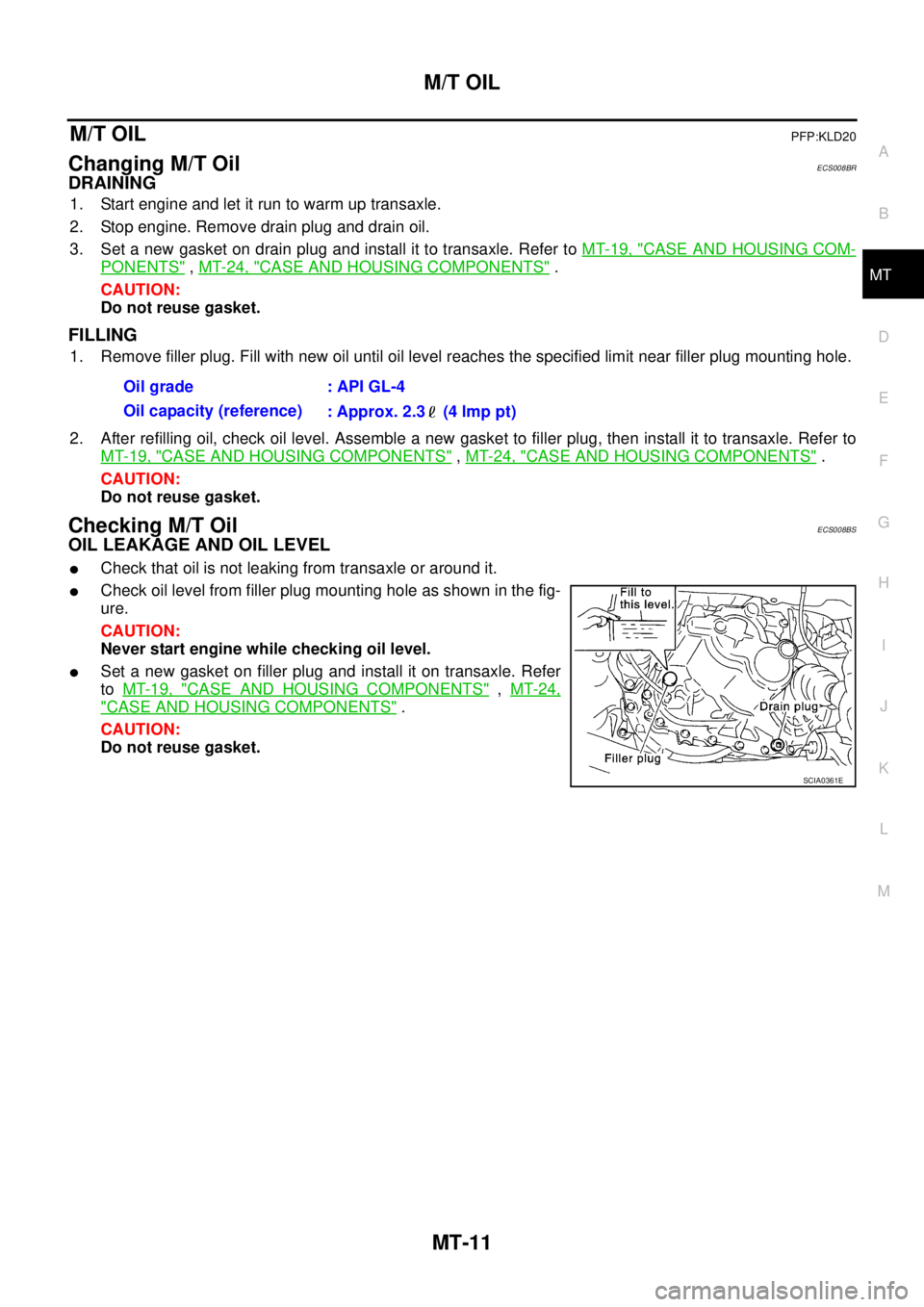
Checking M/T OilECS008BS
OIL LEAKAGE AND OIL LEVEL
�Check that oil is not leaking from transaxle or around it.
�Check oil level from filler plug mounting hole as shown in the fig-
ure.
CAUTION:
Never start engine while checking oil level.
�Set a new gasket on filler plug and install it on transaxle. Refer
to MT-19, "
CASE AND HOUSING COMPONENTS" , MT-24,
"CASE AND HOUSING COMPONENTS" .
CAUTION:
Do not reuse gasket.Oil grade : API GL-4
Oil capacity (reference)
: Approx. 2.3 (4 lmp pt)
SCIA0361E