Page 1894 of 4179
![NISSAN X-TRAIL 2003 Service Repair Manual FL-16
[YD22DDTi]
FUEL SYSTEM
FUEL SYSTEMPFP:17503
Checking Fuel LinesEBS00BKH
Inspect fuel lines, filler cap and tank for improper attachment, leaks,
cracks, damage, loose connections, chafing or de](/manual-img/5/57404/w960_57404-1893.png "NISSAN X-TRAIL 2003 Service Repair Manual FL-16
[YD22DDTi]
FUEL SYSTEM
FUEL SYSTEMPFP:17503
Checking Fuel LinesEBS00BKH
Inspect fuel lines, filler cap and tank for improper attachment, leaks,
cracks, damage, loose connections, chafing or de")
FL-16
[YD22DDTi]
FUEL SYSTEM
FUEL SYSTEMPFP:17503
Checking Fuel LinesEBS00BKH
Inspect fuel lines, filler cap and tank for improper attachment, leaks,
cracks, damage, loose connections, chafing or deterioration.
If necessary, repair or replace damaged parts.
General PrecautionsEBS00BKI
WARNING:
When replacing fuel line parts, be sure to observe the following.
�Put a “CAUTION: INFLAMMABLE” sign in workshop.
�Be sure to work in a well-ventilated area and furnish workshop with a CO2 fire extinguisher.
�Do not smoke while servicing fuel system. Keep open flames and spark away from work area.
CAUTION:
�Before removing fuel line parts, perform the following procedures:
–Put drained fuel in an explosion-proof container and put the lid on securely. Keep the container in
safe area.
–Disconnect negative battery terminal.
�Always replace O-ring and clamps with new ones.
�Do not kink or twist tubes when they are being installed.
�Do not tighten hose clamps excessively to avoid damaging hoses.
�After connecting fuel tube quick connectors, make sure
quick connectors are secure.
Ensure that connector and resin tube do not contact any
adjacent parts.
�After installing tubes, make sure there is no fuel leakage at
connections in the following steps.
–Start the engine and rev it up and check for fuel leaks at
connections.
SMA803A
SBIA0504E
Page 1895 of 4179
![NISSAN X-TRAIL 2003 Service Repair Manual FUEL FILTER
FL-17
[YD22DDTi]
C
D
E
F
G
H
I
J
K
L
MA
FL
FUEL FILTERPFP:16400
Removal and InstallationEBS00BLA
REMOVAL
1. Remove air duct, air cleaner case and mass air flow sensor assembly. Refer to](/manual-img/5/57404/w960_57404-1894.png "NISSAN X-TRAIL 2003 Service Repair Manual FUEL FILTER
FL-17
[YD22DDTi]
C
D
E
F
G
H
I
J
K
L
MA
FL
FUEL FILTERPFP:16400
Removal and InstallationEBS00BLA
REMOVAL
1. Remove air duct, air cleaner case and mass air flow sensor assembly. Refer to")
FUEL FILTER
FL-17
[YD22DDTi]
C
D
E
F
G
H
I
J
K
L
MA
FL
FUEL FILTERPFP:16400
Removal and InstallationEBS00BLA
REMOVAL
1. Remove air duct, air cleaner case and mass air flow sensor assembly. Refer to EM-133, "AIR CLEANER
AND AIR DUCT" .
2. Remove fuel filter protector.
3. Disconnect fuel hoses at fuel filter bracket.
CAUTION:
Plug the pipe to prevent fuel from draining.
4. Remove fuel filter with fuel filter bracket.
CAUTION:
Do not splash fuel during removal. If fuel is splashed,
immediately wipe it off.
5. Using band-type fuel filter wrench (commercial service tool),
remove fuel filter.
6. Turn fuel filter upside down to drain fuel.
7. Remove drain plug from fuel filter.
INSTALLATION
Note the following, and install in the reverse order of removal.
�Replace O-ring on drain plug with new one.
�Screw the fuel filter by hand until packing contacts sealing surface of bracket. Then tighten it by turning
approximately 2/3 turn.
�After installation, bleed air from fuel line. Refer to FL-18, "Air Bleeding" .
INSPECTION AFTER INSTALLATION
Make sure there is no fuel leakage at connections in the following steps.
�Start the engine and rev it up and make sure there is no fuel leakage at connections.
PBIC2501E
SBIA0135E
SBIA0136E
Drain plug
: 4.9 N·m (0.5 kg-m, 43 in-lb)
Page 1896 of 4179
![NISSAN X-TRAIL 2003 Service Repair Manual FL-18
[YD22DDTi]
FUEL FILTER
Air BleedingEBS00BLB
After fuel filter is replaced and after fuel system components are
removed/installed, bleed air from fuel line as follows:
�Move priming pump up and](/manual-img/5/57404/w960_57404-1895.png "NISSAN X-TRAIL 2003 Service Repair Manual FL-18
[YD22DDTi]
FUEL FILTER
Air BleedingEBS00BLB
After fuel filter is replaced and after fuel system components are
removed/installed, bleed air from fuel line as follows:
�Move priming pump up and")
FL-18
[YD22DDTi]
FUEL FILTER
Air BleedingEBS00BLB
After fuel filter is replaced and after fuel system components are
removed/installed, bleed air from fuel line as follows:
�Move priming pump up and down to bleed air from fuel path.
�When air is bled, pumping of priming pump becomes heavy stop
operation at that time.
�Crank engine until it starts. Do not crank engine for more than
30 seconds.
�If engine does not start, stop cranking and repeat step 1 above.
�If engine does not operate smoothly after it has started, race it
two or three times.
�If air cannot be bled easily (pumping of priming pump does not
become heavy), disconnect feed-side of hose between fuel filter and electronically controlled fuel pump.
After that, operate priming pump and confirm that fuel comes out.
CAUTION:
Prepare a tray to collect fuel. Prevent fuel from adhering to rubber parts, especially the engine
mounting insulator.
Draining Water from Fuel FilterEBS00MRU
1. Prepare a tray at the drain hose open end.
2. Loosen drain cock, and operate priming pump to drain water
from fuel filter.
CAUTION:
�Water in filter is drained with fuel. Prepare larger capacity
pan than fuel filter volume.
�Drained water is mixed with fuel. Prevent fuel from adher-
ing to rubber parts such as engine mounting insulator.
3. After draining, close drain cock by hand.
CAUTION:
If drain cock is tightened excessively, it may be damaged
and fuel will leak. Do not use tools to tighten drain cock.
4. Bleed air in fuel piping. Refer to FL-18, "
Air Bleeding" .
5. Start engine and make sure there is no fuel leakage.
SBIA0137E
SBIA0138E
Page 1900 of 4179
![NISSAN X-TRAIL 2003 Service Repair Manual FL-22
[YD22DDTi]
FUEL LEVEL SENSOR UNIT
INSPECTION AFTER REMOVAL
Make sure fuel pump strainer is free from foreign materials. If any are found, remove them.
INSTALLATION
Note the following, and inst](/manual-img/5/57404/w960_57404-1899.png "NISSAN X-TRAIL 2003 Service Repair Manual FL-22
[YD22DDTi]
FUEL LEVEL SENSOR UNIT
INSPECTION AFTER REMOVAL
Make sure fuel pump strainer is free from foreign materials. If any are found, remove them.
INSTALLATION
Note the following, and inst")
FL-22
[YD22DDTi]
FUEL LEVEL SENSOR UNIT
INSPECTION AFTER REMOVAL
Make sure fuel pump strainer is free from foreign materials. If any are found, remove them.
INSTALLATION
Note the following, and install in the reverse order of removal.
�Connect quick connector as follows.
1. Check connection for damage and foreign materials.
2. Align the connector with the tube, then insert connector straight into tube until a click is heard.
3. After connecting, make sure that the connection is secure by following the steps below.
�Visually confirm that the two tabs are connected to connector.
�Pull the tube and connector to make sure they are securely
connected.
�Install fuel level sensor unit with mating mark (triangular pro-
trusion) facing between two carved lines on fuel tank. (Figure
shows left side of fuel tank.)
NOTE:
On right side of fuel tank, there are three carved lines on fuel
tank. Set mating mark between two outer carved lines.
�Install inspection hole cover with the front mark (arrow) facing front of vehicle (both for RH and LH).
INSPECTION AFTER INSTALLATION
Make sure there is no fuel leakage at connections in the following steps.
�Start engine and rev it up and make sure there is no fuel leakage at connections.
PBIC1653E
PBIC2032E
Page 1903 of 4179
FUEL TANK
FL-25
[YD22DDTi]
C
D
E
F
G
H
I
J
K
L
MA
FL
INSPECTION AFTER INSTALLATION
Make sure there is no fuel leakage at connections in the following steps.
�Start engine and rev it up and make sure there is no fuel leakage at connections.
Page 1905 of 4179
EX-1
EXHAUST SYSTEM
B ENGINE
CONTENTS
C
D
E
F
G
H
I
J
K
L
M
SECTION
A
EX
EXHAUST SYSTEM
EXHAUST SYSTEM ................................................... 2
Checking Exhaust System ....................................... 2
Removal and Installation .......................................... 2
QR20DE AND QR25DE ........................................ 2
YD22DDTI ............................................................. 3
REMOVAL ............................................................. 3
INSTALLATION ..................................................... 3
INSPECTION AFTER INSTALLATION ................. 4SERVICE DATA AND SPECIFICATIONS (SDS) ........ 5
Tightening Torque ..................................................... 5
QR20DE AND QR25DE ........................................ 5
YD22DDTI ............................................................. 5
Page 1906 of 4179
EX-2
EXHAUST SYSTEM
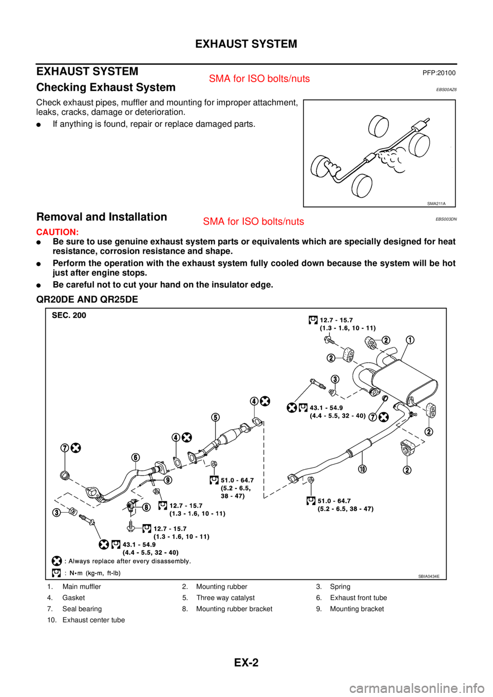
EXHAUST SYSTEMPFP:20100
Checking Exhaust SystemEBS00AZ6
Check exhaust pipes, muffler and mounting for improper attachment,
leaks, cracks, damage or deterioration.
�If anything is found, repair or replace damaged parts.
Removal and InstallationEBS003DN
CAUTION:
�Be sure to use genuine exhaust system parts or equivalents which are specially designed for heat
resistance, corrosion resistance and shape.
�Perform the operation with the exhaust system fully cooled down because the system will be hot
just after engine stops.
�Be careful not to cut your hand on the insulator edge.
QR20DE AND QR25DE
SMA211A
1. Main muffler 2. Mounting rubber 3. Spring
4. Gasket 5. Three way catalyst 6. Exhaust front tube
7. Seal bearing 8. Mounting rubber bracket 9. Mounting bracket
10. Exhaust center tube
SBIA0434E
Page 1908 of 4179
EX-4
EXHAUST SYSTEM
Exhaust Front Tube Side (QR20DE and QR25DE)
Insert seal bearing in the direction shown in the figure.
CAUTION:
Tighten mounting bolt without causing interference with
exhaust front tube flange.
Main Muffler Side (QR20DE, QR25DE and YD22DDTi)
Insert seal bearing in the direction shown in the figure.
CAUTION:
Tighten mounting bolt without causing interference with main
muffler flange.
INSPECTION AFTER INSTALLATION
�With the engine running, check exhaust tube joints for gas leakage and unusual noises.
�Check to ensure that mounting brackets and mounting rubbers are installed properly and free from undue
stress. Improper installation could result in excessive noise and vibration.
PBIC2274E
PBIC2275E


Insert seal bearing in the direction shown in the figure.
CAUTION:
Tighten mounting bolt without causing interference with
exhaust fro")