Page 2094 of 4179
AT-58
[EURO-OBD]
TROUBLE DIAGNOSIS — INTRODUCTION
DIAGNOSTIC WORKSHEET
Information from Customer
KEY POINTS
�WHAT..... Vehicle & A/T model
�WHEN..... Date, Frequencies
�WHERE..... Road conditions
�HOW..... Operating conditions, Symptoms
Customer name MR/MS Model & Year VIN
Trans. model Engine Mileage
Incident Date Manuf. Date In Service Date
Frequency❏ Continuous❏ Intermittent ( times a day)
Symptoms❏ Vehicle does not move. (❏ Any position❏ Particular position)
❏ No up-shift (❏ 1st → 2nd❏ 2nd → 3rd❏ 3rd → O/D)
❏ No down-shift (❏ O/D → 3rd❏ 3rd → 2nd❏ 2nd → 1st)
❏ Lockup malfunction
❏ Shift point too high or too low.
❏ Shift shock or slip (❏ N → D❏ Lockup❏ Any drive position)
❏ Noise or vibration
❏ No kick down
❏ No pattern select
❏ Others
()
O/D OFF indicator lamp Blinks for about 8 seconds.
❏ Continuously lit❏ Not lit
Malfunction indicator lamp (MIL)❏ Continuously lit❏ Not lit
Page 2095 of 4179
![NISSAN X-TRAIL 2003 Service Repair Manual TROUBLE DIAGNOSIS — INTRODUCTION
AT-59
[EURO-OBD]
D
E
F
G
H
I
J
K
L
MA
B
AT
Diagnostic Worksheet
1.❏ Read the Fail-safe and listen to customer complaints.AT- 5 8
2.❏ Check A/T fluidAT- 6 4
❏](/manual-img/5/57404/w960_57404-2094.png "NISSAN X-TRAIL 2003 Service Repair Manual TROUBLE DIAGNOSIS — INTRODUCTION
AT-59
[EURO-OBD]
D
E
F
G
H
I
J
K
L
MA
B
AT
Diagnostic Worksheet
1.❏ Read the Fail-safe and listen to customer complaints.AT- 5 8
2.❏ Check A/T fluidAT- 6 4
❏")
TROUBLE DIAGNOSIS — INTRODUCTION
AT-59
[EURO-OBD]
D
E
F
G
H
I
J
K
L
MA
B
AT
Diagnostic Worksheet
1.❏ Read the Fail-safe and listen to customer complaints.AT- 5 8
2.❏ Check A/T fluidAT- 6 4
❏ Leakage (Follow specified procedure)
❏ Fluid condition
❏ Fluid level
3.❏ Perform Stall Test and Line Pressure Test.AT- 6 5
, AT- 6 8
❏ Stall test — Mark possible damaged components/others.
❏ Torque converter one-way clutch
❏ Reverse clutch
❏ Forward clutch
❏ Overrun clutch
❏ Forward one-way clutch❏ Low & reverse brake
❏ Low one-way clutch
❏ Engine
❏ Line pressure is low
❏ Clutches and brakes except high clutch and
brake band are OK
❏ Line Pressure test — Suspected parts:
4.❏ Perform all Road Test and mark required procedures.AT- 7 0
4-1. Check before engine is started.AT- 7 1
❏ O/D OFF Indicator Lamp Does Not Come On, AT-204 .
❏ SELF-DIAGNOSTIC PROCEDURE/DIAGNOSTIC TROUBLE CODE (DTC) CONFIRMATION PRO-
CEDURE. — Mark detected items.
❏ PNP switch, AT- 1 0 0
.
❏ A/T fluid temperature sensor, AT- 1 0 6
.
❏ Vehicle speed sensor·A/T (Revolution sensor), AT- 11 2
.
❏ Engine speed signal, AT- 11 9
.
❏ Torque converter clutch solenoid valve, AT-148
.
❏ Line pressure solenoid valve, AT-154
.
❏ Shift solenoid valve A, AT- 1 6 1
.
❏ Shift solenoid valve B, AT- 1 6 7
.
❏ Accelerator pedal position (App) sensor, AT- 1 7 3
.
❏ Overrun clutch solenoid valve, AT- 1 7 8
.
❏ PNP & overdrive control switches, and throttle position sensor, AT- 2 3 7
.
❏ Batt/fluid temp sen (A/T fluid temperature sensor and TCM power source), AT- 1 8 4
.
❏ Vehicle speed sensor·MTR, AT-192
.
❏ CAN communication line, AT- 9 7
.
❏ Control unit (RAM), control unit (ROM), AT-198
.
❏ Control unit (EEP ROM), AT-200
.
❏ Battery
❏ Others
4-2. Check at idleAT- 7 2
❏ Engine Cannot Be Started In “P” And “N” Position, AT-206 .
❏ In “P” Position, Vehicle Moves Forward Or Backward When Pushed, AT-207
.
❏ In “N” Position, Vehicle Moves, AT- 2 0 8
.
❏ Large Shock. “N” → “R” Position, AT-209
.
❏ Vehicle Does Not Creep Backward In “R” Position, AT-210
.
❏ Vehicle Does Not Creep Forward In “D”, “2” Or “1” Position, AT- 2 1 2
.
Page 2096 of 4179
![NISSAN X-TRAIL 2003 Service Repair Manual AT-60
[EURO-OBD]
TROUBLE DIAGNOSIS — INTRODUCTION
4. 4-3. Cruise testAT- 7 4
AT- 7 8Part-1
❏ Vehicle Cannot Be Started From D
1 , AT-214 .
❏ A/T Does Not Shift: D
1 → D2 Or Does Not Kickdo](/manual-img/5/57404/w960_57404-2095.png "NISSAN X-TRAIL 2003 Service Repair Manual AT-60
[EURO-OBD]
TROUBLE DIAGNOSIS — INTRODUCTION
4. 4-3. Cruise testAT- 7 4
AT- 7 8Part-1
❏ Vehicle Cannot Be Started From D
1 , AT-214 .
❏ A/T Does Not Shift: D
1 → D2 Or Does Not Kickdo")
AT-60
[EURO-OBD]
TROUBLE DIAGNOSIS — INTRODUCTION
4. 4-3. Cruise testAT- 7 4
AT- 7 8Part-1
❏ Vehicle Cannot Be Started From D
1 , AT-214 .
❏ A/T Does Not Shift: D
1 → D2 Or Does Not Kickdown: D4 → D2 , AT- 2 1 7 .
❏ A/T Does Not Shift: D
2 → D3 , AT-220 .
❏ A/T Does Not Shift: D
3 → D4 , AT-222 .
❏ A/T Does Not Perform Lock-up, AT- 2 2 4
.
❏ A/T Does Not Hold Lock-up Condition, AT- 2 2 5
.
❏ Lock-up Is Not Released, AT- 2 2 7
.
❏ Engine Speed Does Not Return To Idle (Light Braking D
4 → D3 ), AT- 2 2 8 .
Part-2AT- 8 1
❏ Vehicle Does Not Start From D1 , AT-230 .
❏ A/T Does Not Shift: D
1 → D2 Or Does Not Kickdown: D4 → D2 , AT- 2 1 7 .
❏ A/T Does Not Shift: D
2 → D3 , AT-220 .
❏ A/T Does Not Shift: D
3 → D4 , AT-222 .
Part-3AT- 8 2
❏ A/T Does Not Shift: D4 → D3 When Overdrive Control Switch “ON” → “OFF”, AT- 2 3 1 .
❏ Engine Speed Does Not Return To Idle (Engine Brake In D
3 ), AT-228 .
❏ A/T Does Not Shift: D
3 → 22 , When Selector Lever “D” → “2” Position, AT-232 .
❏ Engine Speed Does Not Return To Idle (Engine Brake In 2
2 ), AT- 2 2 8 .
❏ A/T Does Not Shift: 2
2 → 11 , When Selector Lever “2” → “1” Position, AT- 2 3 3 .
❏ Vehicle Does Not Decelerate By Engine Brake, AT-235
.
❏ TCM Self-diagnosis Does Not Activate (PNP & Overdrive control switches, and throttle position sensor
circuit checks), AT-237
.
❏ SELF-DIAGNOSTIC PROCEDURE/DIAGNOSTIC TROUBLE CODE (DTC) CONFIRMATION PRO-
CEDURE — Mark detected items.
❏ PNP switch, AT-100
.
❏ A/T fluid temperature sensor, AT-106
.
❏ Vehicle speed sensor·A/T (Revolution sensor), AT- 11 2
.
❏ Engine speed signal, AT- 11 9
.
❏ Torque converter clutch solenoid valve, AT- 1 4 8
.
❏ Line pressure solenoid valve, AT-154
.
❏ Shift solenoid valve A, AT-161
.
❏ Shift solenoid valve B, AT-167
.
❏ Accelerator pedal position (App) sensor, AT-173
.
❏ Overrun clutch solenoid valve, AT-178
.
❏ PNP & overdrive control switches, and throttle position sensor, AT- 2 3 7
.
❏ A/T fluid temperature sensor and TCM power source, AT-184
.
❏ Vehicle speed sensor·MTR, AT- 1 9 2
.
❏ CAN communication line, AT- 9 7
.
❏ Control unit (RAM), control unit (ROM), AT- 1 9 8
.
❏ Control unit (EEP ROM), AT- 2 0 0
.
❏ Battery
❏ Others
5.❏ For self-diagnosis NG items, inspect each component. Repair or replace the damaged parts.AT- 5 2
6.❏ Perform all Road Test and re-mark required procedures.AT- 7 0
7.❏ Perform DTC Confirmation Procedure for following MILL indicating items and check out NG items.EC-52
❏ DTC (P0731) A/T 1st gear function, AT-125 .
❏ DTC (P0732) A/T 2nd gear function, AT- 1 3 0
.
❏ DTC (P0733) A/T 3rd gear function, AT-135
.
❏ DTC (P0734) A/T 4th gear function, AT-140
.
8.❏ Perform the Diagnostic Procedures for all remaining items marked NG. Repair or replace the damaged parts.
Refer to the Symptom Chart when you perform the procedures. (The chart also shows some other possible
symptoms and the component inspection orders.)AT- 8 5
9.❏ Erase DTC from TCM and ECM memories.AT- 4 2
Page 2100 of 4179
AT-64
[EURO-OBD]
TROUBLE DIAGNOSIS — BASIC INSPECTION
TROUBLE DIAGNOSIS — BASIC INSPECTIONPFP:00000
A/T Fluid CheckECS004QQ
FLUID LEAKAGE CHECK
1. Clean area suspected of leaking. — for example, mating surface
of converter housing and transmission case.
2. Start engine, apply foot brake, place selector lever in D position
and wait a few minutes.
3. Stop engine.
4. Check for fresh leakage.
FLUID CONDITION CHECK
FLUID LEVEL CHECK
Refer to AT- 1 6 , "Checking A/T Fluid" .
SAT767B
SAT288G
Fluid color Suspected problem
Dark or black with burned odor Wear of frictional material
Milky pink Water contamination — Road water
entering through filler tube or breather
Varnished fluid, light to dark brown and
tackyOxidation — Over or under filling, —
Overheating
SAT638A
Page 2101 of 4179
TROUBLE DIAGNOSIS — BASIC INSPECTION
AT-65
[EURO-OBD]
D
E
F
G
H
I
J
K
L
MA
B
AT
Stall TestECS004QR
STALL TEST PROCEDURE
1. Check A/T fluid and engine oil levels. If necessary, add.
2. Drive vehicle for approx. 10 minutes or until fluid and oil reach
operating temperature. Refer to AT- 1 6 , "
Checking A/T Fluid" .
3. Set parking brake and block wheels.
4. Install a tachometer where it can be seen by driver during test.
�It is good practice to mark the point of specified engine
rpm on indicator.
5. Start engine, apply foot brake, and place selector lever in D
position.
6. Accelerate to wide open throttle gradually while applying foot
brake.
7. Quickly note the engine stall revolution and immediately release
throttle.
�During test, never hold throttle wide open for more than 5
seconds.
SAT647B
SAT513G
SAT775B
Stall revolution:
QR20DE: 2,450 - 2,950 rpm
QR25DE: 2,300 - 2,750 rpm
SAT514G
Page 2102 of 4179
![NISSAN X-TRAIL 2003 Service Repair Manual AT-66
[EURO-OBD]
TROUBLE DIAGNOSIS — BASIC INSPECTION
8. Move selector lever to N position.
9. Cool off ATF.
�Run engine at idle for at least one minute.
10. Repeat steps 5 through 9 with selector](/manual-img/5/57404/w960_57404-2101.png "NISSAN X-TRAIL 2003 Service Repair Manual AT-66
[EURO-OBD]
TROUBLE DIAGNOSIS — BASIC INSPECTION
8. Move selector lever to N position.
9. Cool off ATF.
�Run engine at idle for at least one minute.
10. Repeat steps 5 through 9 with selector")
AT-66
[EURO-OBD]
TROUBLE DIAGNOSIS — BASIC INSPECTION
8. Move selector lever to N position.
9. Cool off ATF.
�Run engine at idle for at least one minute.
10. Repeat steps 5 through 9 with selector lever in 2, 1 and R posi-
tions.
JUDGEMENT OF STALL TEST
The test result and possible damaged components relating to each result are shown in the illustrations on next
page.
In order to pinpoint the possible damaged components, follow the WORK FLOW shown in AT- 6 1 , "
Work Flow"
(EURO-OBD).
NOTE:
Stall revolution is too high in D, 2 or 1 position:
�Slippage occurs in 1st gear but not in 2nd and 3rd gears...... Low one-way clutch slippage
�Slippage occurs in the following gears:
1st through 3rd gears in D position and engine brake functions with overdrive control switch set to OFF.
1st and 2nd gears in 2 position and engine brake functions with accelerator pedal released (fully closed
throttle)...... Forward clutch or forward one-way clutch slippage
Stall revolution is too high in R position:
�Engine brake does not function in 1 position...... Low & reverse brake slippage
�Engine brake functions in 1 position...... Reverse clutch slippage
Stall revolution within specifications:
�Vehicle does not achieve speed of more than 80 km/h (50 MPH)...... One-way clutch seizure in torque
converter housing
CAUTION:
Be careful since automatic fluid temperature increases abnormally.
�Slippage occurs in 3rd and 4th gears in D position...... High clutch slippage
�Slippage occurs in 2nd and 4th gear in D position...... Brake band slippage
�Engine brake does not function in 2nd and 3rd gears in D position, 2nd gear in 2 position, and 1st gear in
1 position with overdrive control switch set to OFF...... Overrun clutch slippage
Stall revolution less than specifications:
�Poor acceleration during starts...... One-way clutch slippage in torque converter
SAT771B
Page 2104 of 4179
AT-68
[EURO-OBD]
TROUBLE DIAGNOSIS — BASIC INSPECTION
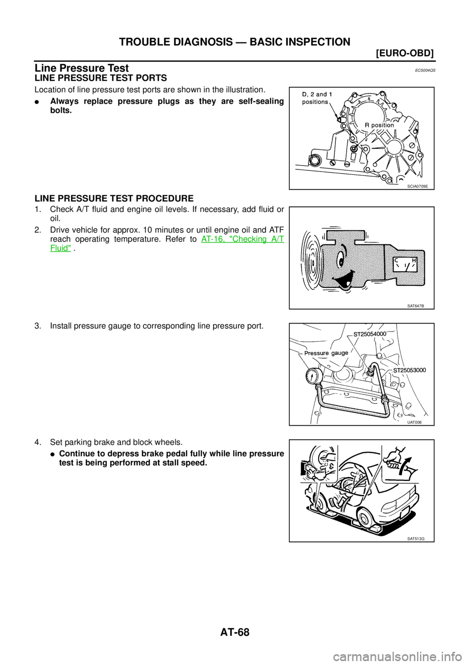
Line Pressure TestECS004QS
LINE PRESSURE TEST PORTS
Location of line pressure test ports are shown in the illustration.
�Always replace pressure plugs as they are self-sealing
bolts.
LINE PRESSURE TEST PROCEDURE
1. Check A/T fluid and engine oil levels. If necessary, add fluid or
oil.
2. Drive vehicle for approx. 10 minutes or until engine oil and ATF
reach operating temperature. Refer to AT- 1 6 , "
Checking A/T
Fluid" .
3. Install pressure gauge to corresponding line pressure port.
4. Set parking brake and block wheels.
�Continue to depress brake pedal fully while line pressure
test is being performed at stall speed.
SCIA0709E
SAT647B
UAT008
SAT513G
Page 2105 of 4179
![NISSAN X-TRAIL 2003 Service Repair Manual TROUBLE DIAGNOSIS — BASIC INSPECTION
AT-69
[EURO-OBD]
D
E
F
G
H
I
J
K
L
MA
B
AT
5. Start engine and measure line pressure at idle and stall speed.
�When measuring line pressure at stall speed, fol](/manual-img/5/57404/w960_57404-2104.png "NISSAN X-TRAIL 2003 Service Repair Manual TROUBLE DIAGNOSIS — BASIC INSPECTION
AT-69
[EURO-OBD]
D
E
F
G
H
I
J
K
L
MA
B
AT
5. Start engine and measure line pressure at idle and stall speed.
�When measuring line pressure at stall speed, fol")
TROUBLE DIAGNOSIS — BASIC INSPECTION
AT-69
[EURO-OBD]
D
E
F
G
H
I
J
K
L
MA
B
AT
5. Start engine and measure line pressure at idle and stall speed.
�When measuring line pressure at stall speed, follow the
stall test procedure.
LINE PRESSURE
JUDGEMENT OF LINE PRESSURE TEST
SAT493G
Check lock-up hold.Line pressure kPa (bar, kg/cm2 , psi)
“D”, “2” and “1” positions “R” position
Idle 500 (5.00, 5.1, 73) 778 (7.78, 7.9, 113)
Stall 1,233 (12.33, 12.6, 179) 1,918 (19.18, 19.6, 278)
Judgement Suspected parts
At idleLine pressure is low in all positions.
�Oil pump wear
�Control piston damage
�Pressure regulator valve or plug sticking
�Spring for pressure regulator valve damaged
�Fluid pressure leakage between oil strainer and pressure regulator valve
�Clogged strainer
Line pressure is low in particular posi-
tion.
�Fluid pressure leakage between manual valve and particular clutch
�For example, line pressure is:
− Low in “R” and “1” positions, but
− Normal in “D” and “2” positions.
Therefore, fluid leakage exists at or around low and reverse brake circuit.
Refer to AT- 2 3
.
Line pressure is high.
�Maladjustment of throttle position sensor
�A/T fluid temperature sensor damaged
�Line pressure solenoid valve sticking
�Short circuit of line pressure solenoid valve circuit
�Pressure modifier valve sticking
�Pressure regulator valve or plug sticking
�Open in dropping resistor circuit
At stall
speedLine pressure is low.
�Maladjustment of throttle position sensor
�Line pressure solenoid valve sticking
�Short circuit of line pressure solenoid valve circuit
�Pressure regulator valve or plug sticking
�Pressure modifier valve sticking
�Pilot valve sticking

![NISSAN X-TRAIL 2003 Service Repair Manual AT-64
[EURO-OBD]
TROUBLE DIAGNOSIS — BASIC INSPECTION
TROUBLE DIAGNOSIS — BASIC INSPECTIONPFP:00000
A/T Fluid CheckECS004QQ
FLUID LEAKAGE CHECK
1. Clean area suspected of leaking. — for exampl](/manual-img/5/57404/w960_57404-2099.png "NISSAN X-TRAIL 2003 Service Repair Manual AT-64
[EURO-OBD]
TROUBLE DIAGNOSIS — BASIC INSPECTION
TROUBLE DIAGNOSIS — BASIC INSPECTIONPFP:00000
A/T Fluid CheckECS004QQ
FLUID LEAKAGE CHECK
1. Clean area suspected of leaking. — for exampl")
![NISSAN X-TRAIL 2003 Service Repair Manual TROUBLE DIAGNOSIS — BASIC INSPECTION
AT-65
[EURO-OBD]
D
E
F
G
H
I
J
K
L
MA
B
AT
Stall TestECS004QR
STALL TEST PROCEDURE
1. Check A/T fluid and engine oil levels. If necessary, add.
2. Drive vehicl](/manual-img/5/57404/w960_57404-2100.png "NISSAN X-TRAIL 2003 Service Repair Manual TROUBLE DIAGNOSIS — BASIC INSPECTION
AT-65
[EURO-OBD]
D
E
F
G
H
I
J
K
L
MA
B
AT
Stall TestECS004QR
STALL TEST PROCEDURE
1. Check A/T fluid and engine oil levels. If necessary, add.
2. Drive vehicl")