2003 NISSAN X-TRAIL display
[x] Cancel search: displayPage 579 of 3066

ATC-1
AUTOMATIC AIR CONDITIONER
J AIR CONDITIONER
CONTENTS
C
D
E
F
G
H
I
K
L
M
SECTION
A
B
AT C
AUTOMATIC AIR CONDITIONER
PRECAUTIONS .......................................................... 4
Precautions for Supplemental Restraint System
(SRS) “AIR BAG” and “SEAT BELT PRE-TEN-
SIONER” .................................................................. 4
Precautions for Working with HFC-134a (R-134a)..... 4
General Refrigerant Precautions .............................. 4
Lubricant Precautions .............................................. 5
Precautions for Refrigerant Connection ................... 5
FEATURES OF NEW TYPE REFRIGERANT
CONNECTION ...................................................... 5
O-RING AND REFRIGERANT CONNECTION..... 6
Precautions for Servicing Compressor ..................... 7
Precautions for Service Equipment .......................... 8
RECOVERY/RECYCLING EQUIPMENT .............. 8
ELECTRONIC LEAK DETECTOR ........................ 8
VACUUM PUMP ................................................... 8
MANIFOLD GAUGE SET ...................................... 8
SERVICE HOSES ................................................. 9
SERVICE COUPLERS .......................................... 9
REFRIGERANT WEIGHT SCALE ........................ 9
CALIBRATING ACR4 WEIGHT SCALE ................ 9
CHARGING CYLINDER ...................................... 10
Precautions for Leak Detection Dye ....................... 10
IDENTIFICATION ................................................ 10
IDENTIFICATION LABEL FOR VEHICLE ........... 10
Wiring Diagrams and Trouble Diagnosis ................ 10
PREPARATION ..........................................................11
Special Service Tools ..............................................11
WITH GASOLINE ENGINE (CWV-615M COM-
PRESSOR) ..........................................................11
WITH DIESEL ENGINE (DKV-11G COMPRES-
SOR) ....................................................................11
HFC-134a (R-134a) Service Tools and Equipment... 12
REFRIGERATION SYSTEM ..................................... 16
Refrigerant Cycle ................................................... 16
REFRIGERANT FLOW ....................................... 16
FREEZE PROTECTION (WITH GASOLINE
ENGINE: CWV-615M COMPRESSOR) .............. 16
Refrigerant System Protection ............................... 16
REFRIGERANT PRESSURE SENSOR (WITHGASOLINE ENGINE: CWV-615M COMPRES-
SOR) ................................................................... 16
DUAL-PRESSURE SWITCH (WITH DIESEL
ENGINE: DKV-11G COMPRESSOR) .................. 16
PRESSURE RELIEF VALVE (WITH GASOLINE
ENGINE: CWV-615M COMPRESSOR) .............. 16
V-6 Variable Displacement Compressor (With Gas-
oline Engine: CWV-165M Compressor) .................. 17
GENERAL INFORMATION ................................. 17
DESCRIPTION .................................................... 17
Component Layout ................................................. 20
LUBRICANT .............................................................. 21
Maintenance of Lubricant Quantity in Compressor... 21
LUBRICANT ........................................................ 21
LUBRICANT RETURN OPERATION .................. 21
LUBRICANT ADJUSTING PROCEDURE FOR
COMPONENTS REPLACEMENT EXCEPT
COMPRESSOR .................................................. 22
LUBRICANT ADJUSTING PROCEDURE FOR
COMPRESSOR REPLACEMENT ....................... 22
AIR CONDITIONER CONTROL ............................... 24
Overview Air Conditioner LAN Control System ...... 24
System Construction .............................................. 24
OPERATION ........................................................ 24
TRANSMISSION DATA AND TRANSMISSION
ORDER ............................................................... 25
AIR MIX DOOR CONTROL (AUTOMATIC TEM-
PERATURE CONTROL) ..................................... 25
FAN SPEED CONTROL ...................................... 26
INTAKE DOOR CONTROL ................................. 26
OUTLET DOOR CONTROL ................................ 26
MAGNET CLUTCH CONTROL ........................... 26
SELF-DIAGNOSTIC SYSTEM ............................ 26
Overview of Control system .................................... 26
Control Operation ................................................... 27
DISPLAY SCREEN .............................................. 27
AUTO SWITCH ................................................... 27
TEMPERATURE DIAL (POTENTIO TEMPERA-
TURE CONTROL) ............................................... 27
A/C SWITCH ....................................................... 27
Page 587 of 3066
PRECAUTIONS
ATC-9
C
D
E
F
G
H
I
K
L
MA
B
AT C
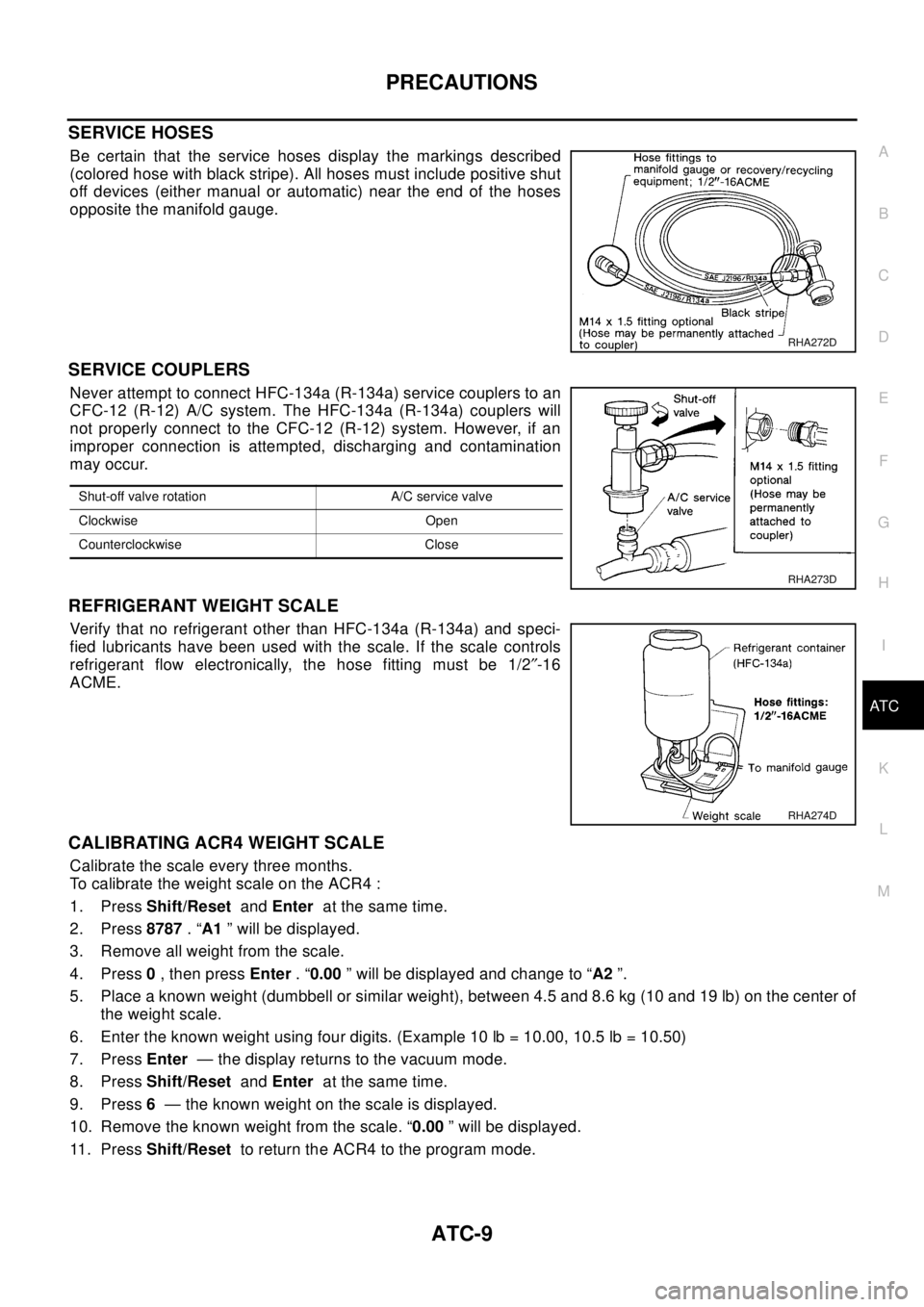
SERVICE HOSES
Be certain that the service hoses display the markings described
(colored hose with black stripe). All hoses must include positive shut
off devices (either manual or automatic) near the end of the hoses
opposite the manifold gauge.
SERVICE COUPLERS
Never attempt to connect HFC-134a (R-134a) service couplers to an
CFC-12 (R-12) A/C system. The HFC-134a (R-134a) couplers will
not properly connect to the CFC-12 (R-12) system. However, if an
improper connection is attempted, discharging and contamination
may occur.
REFRIGERANT WEIGHT SCALE
Verify that no refrigerant other than HFC-134a (R-134a) and speci-
fied lubricants have been used with the scale. If the scale controls
refrigerant flow electronically, the hose fitting must be 1/2²-16
ACME.
CALIBRATING ACR4 WEIGHT SCALE
Calibrate the scale every three months.
To calibrate the weight scale on the ACR4 :
1. PressShift/ResetandEnterat the same time.
2. Press8787.“A1” will be displayed.
3. Remove all weight from the scale.
4. Press0,thenpressEnter.“0.00” will be displayed and change to “A2”.
5. Place a known weight (dumbbell or similar weight), between 4.5 and 8.6 kg (10 and 19 lb) on the center of
the weight scale.
6. Enter the known weight using four digits. (Example 10 lb = 10.00, 10.5 lb = 10.50)
7. PressEnter— the display returns to the vacuum mode.
8. PressShift/ResetandEnterat the same time.
9. Press6— the known weight on the scale is displayed.
10. Remove the known weight from the scale. “0.00” will be displayed.
11 . P r e s sShift/Resetto return the ACR4 to the program mode.
RHA272D
Shut-off valve rotation A/C service valve
Clockwise Open
Counterclockwise Close
RHA273D
RHA274D
Page 600 of 3066

ATC-22
LUBRICANT
4.CHECK ANY PART
Is there any part to be replaced? (Evaporator, condenser,liquid tank or in case there is evidence of a large
amount of lubricant leakage.)
Ye s o r N o
Ye s > > G o t oAT C - 2 2 , "LUBRICANT ADJUSTING PROCEDURE FOR COMPONENTS REPLACEMENT
EXCEPT COMPRESSOR".
No >> Carry out the A/C performance test.
LUBRICANT ADJUSTING PROCEDURE FOR COMPONENTS REPLACEMENT EXCEPT COM-
PRESSOR
After replacing any of the following major components, add the correct amount of lubricant to the system.
Amount of lubricant to be added
*1:If refrigerant leak is small, no addition of lubricant is needed.
LUBRICANT ADJUSTING PROCEDURE FOR COMPRESSOR REPLACEMENT
1. Before connecting ACR4 to vehicle, check ACR4 gauges. No refrigerant pressure should be displayed. If
NG, recover refrigerant from equipment lines.
2. Discharge refrigerant into the refrigerant recovery/recycling equipment. Measure lubricant discharged into
the recovery/recycling equipment.
3. Drain the lubricant from the old (removed) compressor into a graduated container and recover the amount
of lubricant drained.
4. Drain the lubricant from the new compressor into a separate, clean container.
5. Measure an amount of new lubricant installed equal to amount drained from old compressor. Add this
lubricant to new compressor through the suction port opening.
6. Measure an amount of new lubricant equal to the amount recovered during discharging. Add this lubricant
to new compressor through the suction port opening.
7. If the liquid tank also needs to be replaced, add an additional 5 ml [Litre] (0.2 Imp fl oz) of lubricant at this
time.
Do not add this 5 ml (0.2 Imp fl oz) of lubricant if only replacing the compressor.
Part replacedLubricant to be added to system
Remarks
Amount of lubricant
ml [Litre] (Imp fl oz)
Evaporator 75 (2.6) -
Condenser 35 (1.2) -
Liquid tank 10 (0.4) -
In case of refrigerant leak30 (1.1) Large leak
- Small leak *1
Page 605 of 3066
AIR CONDITIONER CONTROL
ATC-27
C
D
E
F
G
H
I
K
L
MA
B
AT C
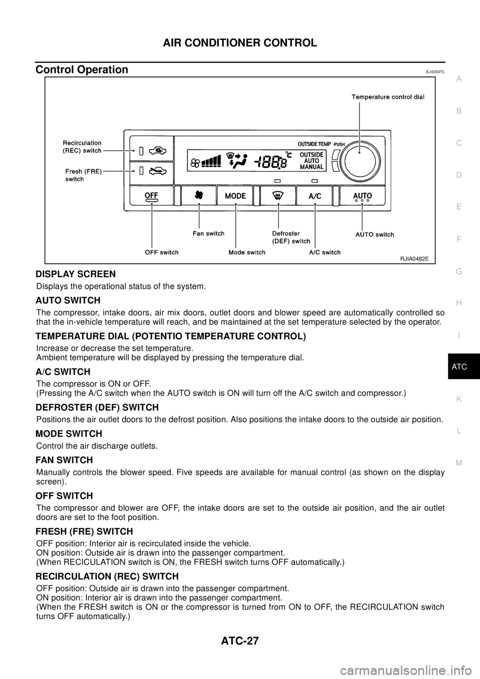
Control OperationEJS000TL
DISPLAY SCREEN
Displays the operational status of the system.
AUTO SWITCH
The compressor, intake doors, air mix doors, outlet doors and blower speed are automatically controlled so
that the in-vehicle temperature will reach, and be maintained at the set temperature selected by the operator.
TEMPERATURE DIAL (POTENTIO TEMPERATURE CONTROL)
Increase or decrease the set temperature.
Ambient temperature will be displayed by pressing the temperature dial.
A/C SWITCH
The compressor is ON or OFF.
(Pressing the A/C switch when the AUTO switch is ON will turn off the A/C switch and compressor.)
DEFROSTER (DEF) SWITCH
Positions the air outlet doors to the defrost position. Also positions the intake doors to the outside air position.
MODE SWITCH
Control the air discharge outlets.
FAN S WIT CH
Manually controls the blower speed. Five speeds are available for manual control (as shown on the display
screen).
OFF SWITCH
The compressor and blower are OFF, the intake doors are set to the outside air position, and the air outlet
doors are set to the foot position.
FRESH (FRE) SWITCH
OFF position: Interior air is recirculated inside the vehicle.
ON position: Outside air is drawn into the passenger compartment.
(When RECICULATION switch is ON, the FRESH switch turns OFF automatically.)
RECIRCULATION (REC) SWITCH
OFF position: Outside air is drawn into the passenger compartment.
ON position: Interior air is drawn into the passenger compartment.
(When the FRESH switch is ON or the compressor is turned from ON to OFF, the RECIRCULATION switch
turns OFF automatically.)
RJIA0482E
Page 622 of 3066
ATC-44
TROUBLE DIAGNOSIS
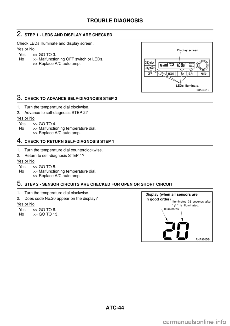
2.STEP 1 - LEDS AND DISPLAY ARE CHECKED
Check LEDs illuminate and display screen.
Ye s o r N o
Yes >>GOTO3.
No >> Malfunctioning OFF switch or LEDs.
>> Replace A/C auto amp.
3.CHECK TO ADVANCE SELF-DIAGNOSIS STEP 2
1. Turn the temperature dial clockwise.
2. Advance to self-diagnosis STEP 2?
Ye s o r N o
Yes >>GOTO4.
No >> Malfunctioning temperature dial.
>> Replace A/C auto amp.
4.CHECK TO RETURN SELF-DIAGNOSIS STEP 1
1. Turn the temperature dial counterclockwise.
2. Return to self-diagnosis STEP 1?
Ye s o r N o
Yes >>GOTO5.
No >> Malfunctioning temperature dial.
>> Replace A/C auto amp.
5.STEP 2 - SENSOR CIRCUITS ARE CHECKED FOR OPEN OR SHORT CIRCUIT
1. Turn the temperature dial clockwise.
2. Does code No.20 appear on the display?
Ye s o r N o
Yes >>GOTO6.
No >> GO TO 13.
RJIA0491E
RHA970DB
Page 623 of 3066
TROUBLE DIAGNOSIS
ATC-45
C
D
E
F
G
H
I
K
L
MA
B
AT C
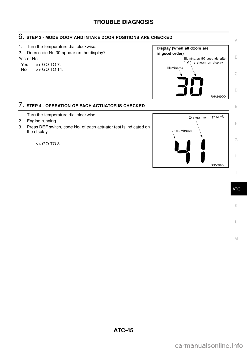
6.STEP 3 - MODE DOOR AND INTAKE DOOR POSITIONS ARE CHECKED
1. Turn the temperature dial clockwise.
2. Does code No.30 appear on the display?
Ye s o r N o
Yes >>GOTO7.
No >> GO TO 14.
7.STEP 4 - OPERATION OF EACH ACTUATOR IS CHECKED
1. Turn the temperature dial clockwise.
2. Engine running.
3. Press DEF switch, code No. of each actuator test is indicated on
the display.
>> GO TO 8.
RHA869DD
RHA495A
Page 624 of 3066
ATC-46
TROUBLE DIAGNOSIS
8.CHECK ACTUATORS
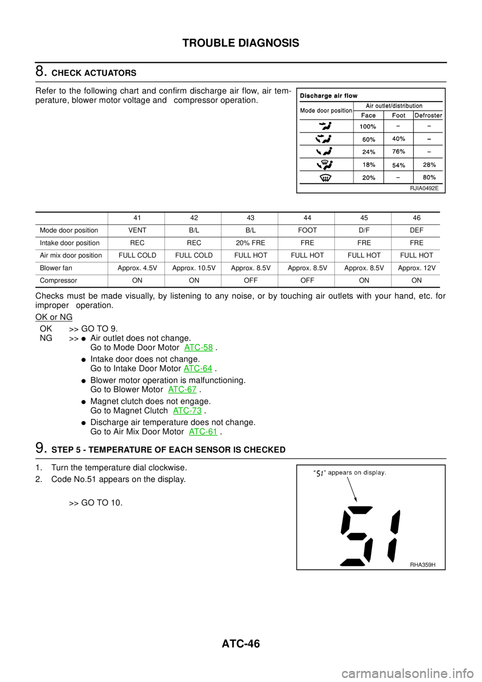
Refer to the following chart and confirm discharge air flow, air tem-
perature, blower motor voltage and compressor operation.
Checks must be made visually, by listening to any noise, or by touching air outlets with your hand, etc. for
improper operation.
OK or NG
OK >> GO TO 9.
NG >>
lAir outlet does not change.
Go to Mode Door MotorAT C - 5 8
.
lIntake door does not change.
Go to Intake Door MotorAT C - 6 4
.
lBlower motor operation is malfunctioning.
Go to Blower MotorAT C - 6 7
.
lMagnet clutch does not engage.
Go to Magnet ClutchAT C - 7 3
.
lDischarge air temperature does not change.
Go to Air Mix Door MotorAT C - 6 1
.
9.STEP 5 - TEMPERATURE OF EACH SENSOR IS CHECKED
1. Turn the temperature dial clockwise.
2. Code No.51 appears on the display.
>> GO TO 10.
RJIA0492E
41 42 43 44 45 46
Mode door position VENT B/L B/L FOOT D/F DEF
Intake door position REC REC 20% FRE FRE FRE FRE
Air mix door position FULL COLD FULL COLD FULL HOT FULL HOT FULL HOT FULL HOT
Blower fan Approx. 4.5V Approx. 10.5V Approx. 8.5V Approx. 8.5V Approx. 8.5V Approx. 12V
Compressor ON ON OFF OFF ON ON
RHA359H
Page 625 of 3066
TROUBLE DIAGNOSIS
ATC-47
C
D
E
F
G
H
I
K
L
MA
B
AT C
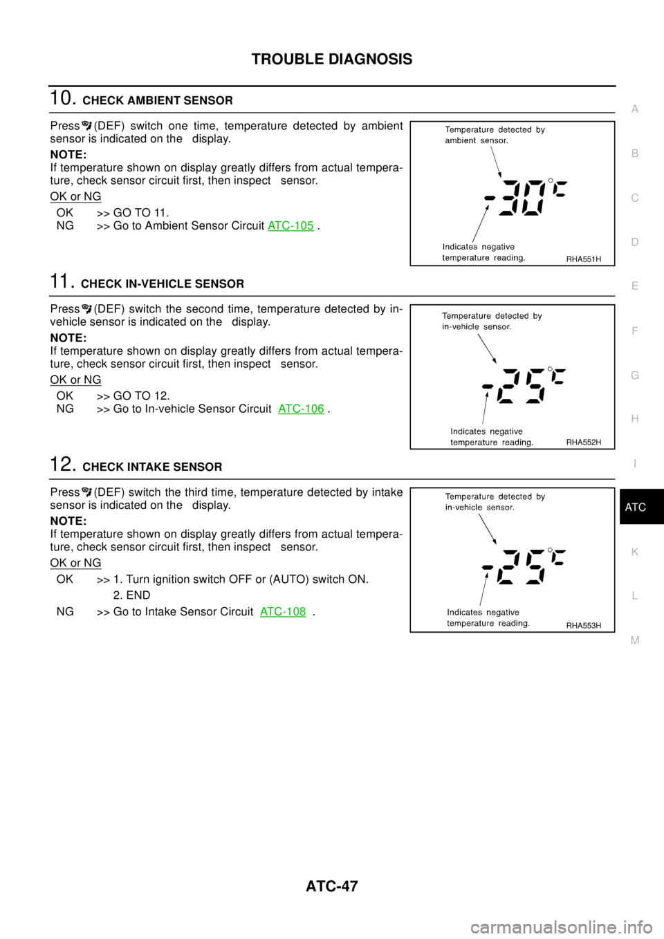
10.CHECK AMBIENT SENSOR
Press (DEF) switch one time, temperature detected by ambient
sensor is indicated on the display.
NOTE:
If temperature shown on display greatly differs from actual tempera-
ture, check sensor circuit first, then inspect sensor.
OK or NG
OK >> GO TO 11.
NG >> Go to Ambient Sensor CircuitAT C - 1 0 5
.
11 .CHECK IN-VEHICLE SENSOR
Press (DEF) switch the second time, temperature detected by in-
vehicle sensor is indicated on the display.
NOTE:
If temperature shown on display greatly differs from actual tempera-
ture, check sensor circuit first, then inspect sensor.
OK or NG
OK >> GO TO 12.
NG >> Go to In-vehicle Sensor CircuitATC-106
.
12.CHECK INTAKE SENSOR
Press (DEF) switch the third time, temperature detected by intake
sensor is indicated on the display.
NOTE:
If temperature shown on display greatly differs from actual tempera-
ture, check sensor circuit first, then inspect sensor.
OK or NG
OK >> 1. Turn ignition switch OFF or (AUTO) switch ON.
2. END
NG >> Go to Intake Sensor CircuitAT C - 1 0 8
.
RHA551H
RHA552H
RHA553H