2003 NISSAN X-TRAIL display
[x] Cancel search: displayPage 824 of 3066
BL-80
NATS (NISSAN ANTI-THEFT SYSTEM)
Diagnostic Procedure 1
EIS001T7
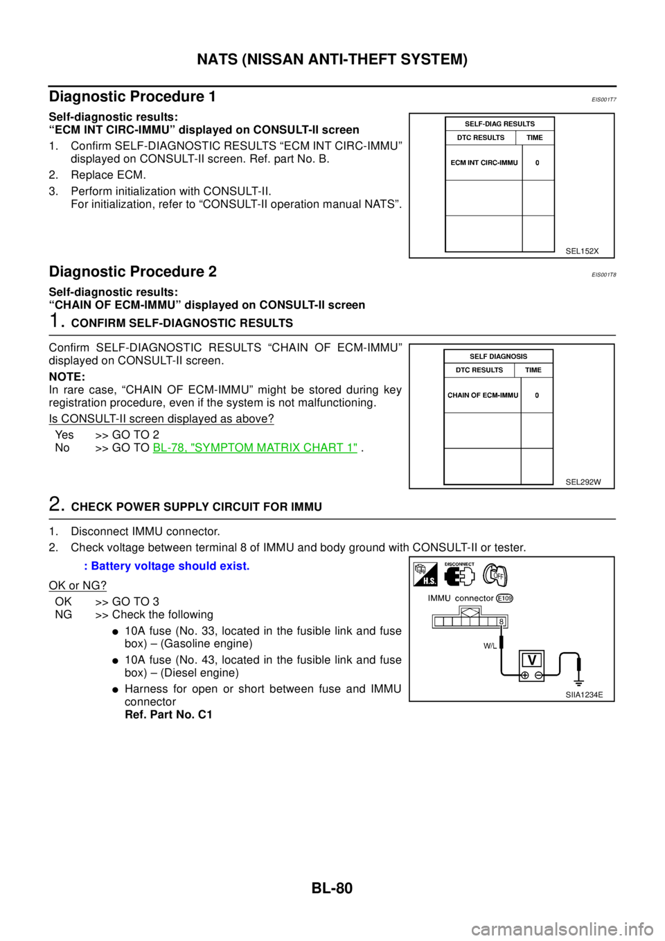
Self-diagnostic results:
“ECM INT CIRC-IMMU” displayed on CONSULT-II screen
1. Confirm SELF-DIAGNOSTIC RESULTS “ECM INT CIRC-IMMU”
displayed on CONSULT-II screen. Ref. part No. B.
2. Replace ECM.
3. Perform initialization with CONSULT-II.
For initialization, refer to “CONSULT-II operation manual NATS”.
Diagnostic Procedure 2EIS001T8
Self-diagnostic results:
“CHAIN OF ECM-IMMU” displayed on CONSULT-II screen
1.CONFIRM SELF-DIAGNOSTIC RESULTS
Confirm SELF-DIAGNOSTIC RESULTS “CHAIN OF ECM-IMMU”
displayed on CONSULT-II screen.
NOTE:
In rare case, “CHAIN OF ECM-IMMU” might be stored during key
registration procedure, even if the system is not malfunctioning.
Is CONSULT-II screen displayed as above?
Yes >>GOTO2
No >> GO TOBL-78, "
SYMPTOM MATRIX CHART 1".
2.CHECK POWER SUPPLY CIRCUIT FOR IMMU
1. Disconnect IMMU connector.
2. Check voltage between terminal 8 of IMMU and body ground with CONSULT-II or tester.
OK or NG?
OK >> GO TO 3
NG >> Check the following
l10A fuse (No. 33, located in the fusible link and fuse
box) – (Gasoline engine)
l10A fuse (No. 43, located in the fusible link and fuse
box) – (Diesel engine)
lHarness for open or short between fuse and IMMU
connector
Ref. Part No. C1
SEL152X
SEL292W
: Battery voltage should exist.
SIIA1234E
Page 826 of 3066
BL-82
NATS (NISSAN ANTI-THEFT SYSTEM)
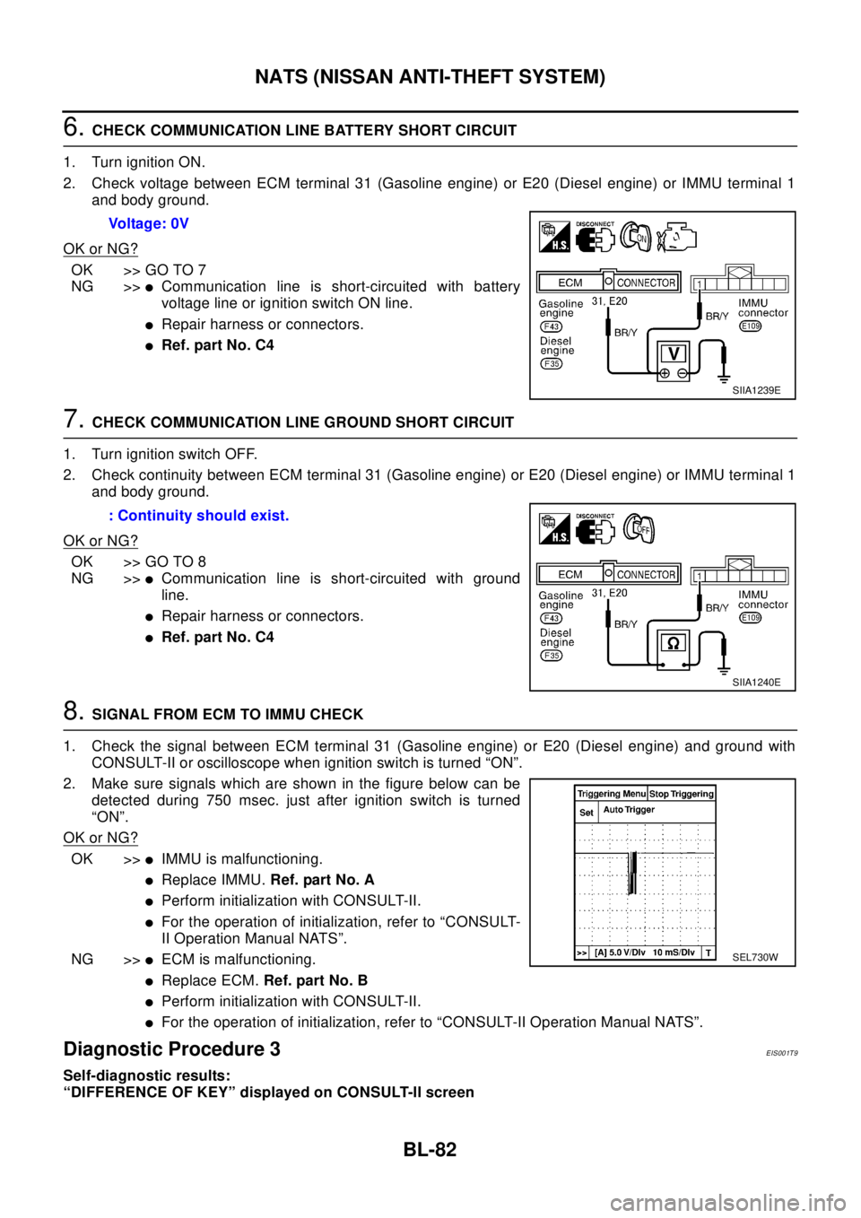
6.CHECK COMMUNICATION LINE BATTERY SHORT CIRCUIT
1. Turn ignition ON.
2. Check voltage between ECM terminal 31 (Gasoline engine) or E20 (Diesel engine) or IMMU terminal 1
and body ground.
OK or NG?
OK >> GO TO 7
NG >>
lCommunication line is short-circuited with battery
voltage line or ignition switch ON line.
lRepair harness or connectors.
lRef. part No. C4
7.CHECK COMMUNICATION LINE GROUND SHORT CIRCUIT
1. Turn ignition switch OFF.
2. Check continuity between ECM terminal 31 (Gasoline engine) or E20 (Diesel engine) or IMMU terminal 1
and body ground.
OK or NG?
OK >> GO TO 8
NG >>
lCommunication line is short-circuited with ground
line.
lRepair harness or connectors.
lRef. part No. C4
8.SIGNAL FROM ECM TO IMMU CHECK
1. Check the signal between ECM terminal 31 (Gasoline engine) or E20 (Diesel engine) and ground with
CONSULT-II or oscilloscope when ignition switch is turned “ON”.
2. Make sure signals which are shown in the figure below can be
detected during 750 msec. just after ignition switch is turned
“ON”.
OK or NG?
OK >>lIMMU is malfunctioning.
lReplace IMMU.Ref. part No. A
lPerform initialization with CONSULT-II.
lFor the operation of initialization, refer to “CONSULT-
II Operation Manual NATS”.
NG >>
lECM is malfunctioning.
lReplace ECM.Ref. part No. B
lPerform initialization with CONSULT-II.
lFor the operation of initialization, refer to “CONSULT-II Operation Manual NATS”.
Diagnostic Procedure 3EIS001T9
Self-diagnostic results:
“DIFFERENCE OF KEY” displayed on CONSULT-II screenVoltage: 0V
SIIA1239E
: Continuity should exist.
SIIA1240E
SEL730W
Page 827 of 3066
NATS (NISSAN ANTI-THEFT SYSTEM)
BL-83
C
D
E
F
G
H
J
K
L
MA
B
BL
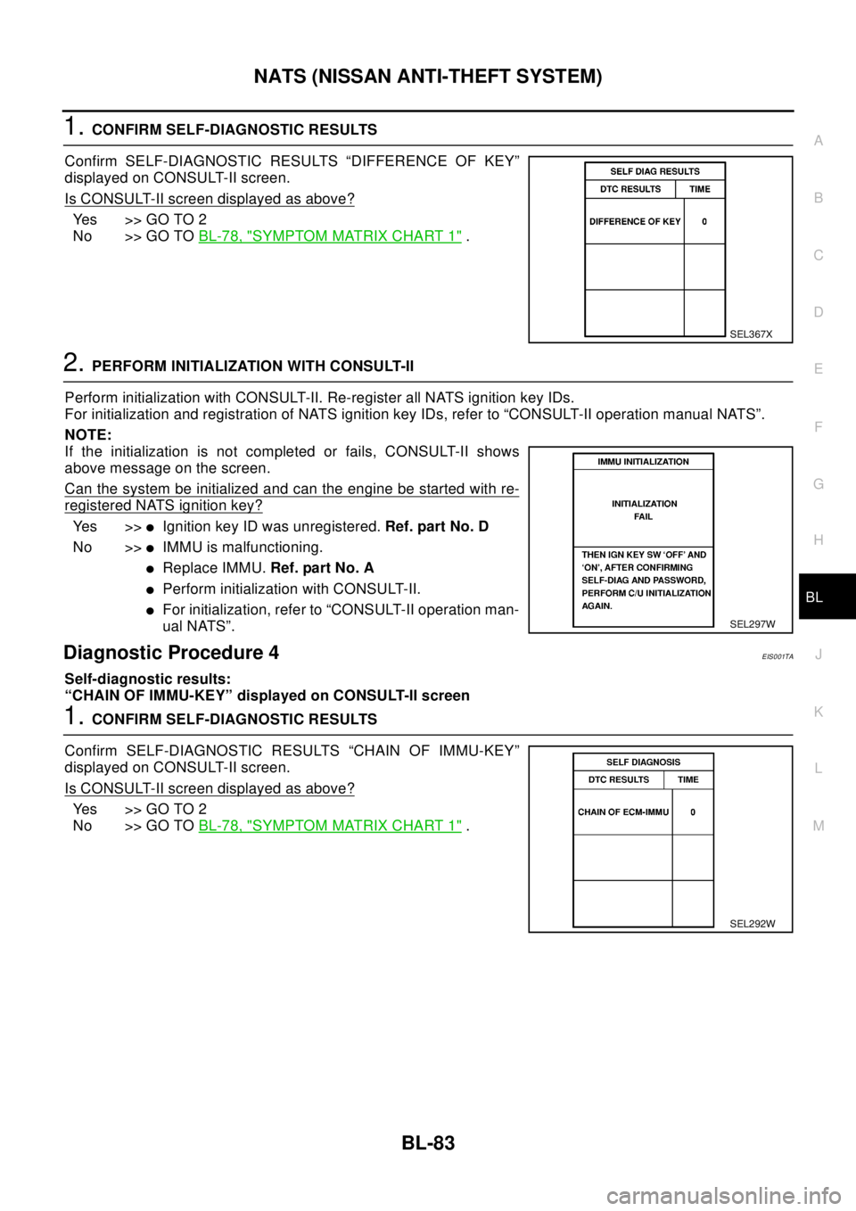
1.CONFIRM SELF-DIAGNOSTIC RESULTS
Confirm SELF-DIAGNOSTIC RESULTS “DIFFERENCE OF KEY”
displayed on CONSULT-II screen.
Is CONSULT-II screen displayed as above?
Yes >>GOTO2
No >> GO TOBL-78, "
SYMPTOM MATRIX CHART 1".
2.PERFORM INITIALIZATION WITH CONSULT-II
Perform initialization with CONSULT-II. Re-register all NATS ignition key IDs.
For initialization and registration of NATS ignition key IDs, refer to “CONSULT-II operation manual NATS”.
NOTE:
If the initialization is not completed or fails, CONSULT-II shows
above message on the screen.
Can the system be initialized and can the engine be started with re-
registered NATS ignition key?
Ye s > >lIgnition key ID was unregistered.Ref. part No. D
No >>
lIMMU is malfunctioning.
lReplace IMMU.Ref. part No. A
lPerform initialization with CONSULT-II.
lFor initialization, refer to “CONSULT-II operation man-
ual NATS”.
Diagnostic Procedure 4EIS001TA
Self-diagnostic results:
“CHAIN OF IMMU-KEY” displayed on CONSULT-II screen
1.CONFIRM SELF-DIAGNOSTIC RESULTS
Confirm SELF-DIAGNOSTIC RESULTS “CHAIN OF IMMU-KEY”
displayed on CONSULT-II screen.
Is CONSULT-II screen displayed as above?
Yes >>GOTO2
No >> GO TOBL-78, "
SYMPTOM MATRIX CHART 1".
SEL367X
SEL297W
SEL292W
Page 829 of 3066
NATS (NISSAN ANTI-THEFT SYSTEM)
BL-85
C
D
E
F
G
H
J
K
L
MA
B
BL
Diagnostic Procedure 5EIS001TB
Self-diagnostic results:
“ID DISCORD, IMM-ECM” displayed on CONSULT-II screen
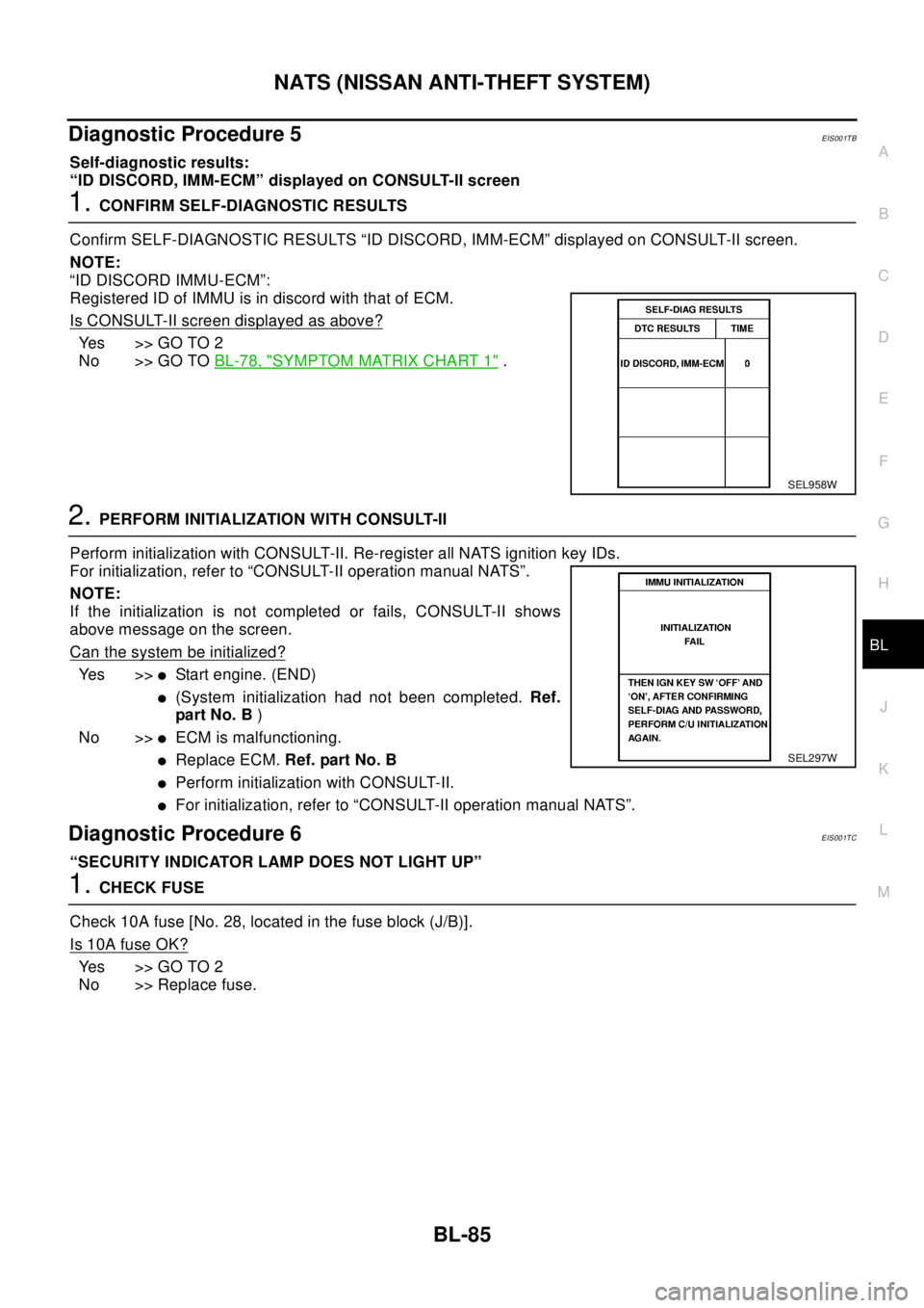
1.CONFIRM SELF-DIAGNOSTIC RESULTS
Confirm SELF-DIAGNOSTIC RESULTS “ID DISCORD, IMM-ECM” displayed on CONSULT-II screen.
NOTE:
“ID DISCORD IMMU-ECM”:
Registered ID of IMMU is in discord with that of ECM.
Is CONSULT-II screen displayed as above?
Yes >>GOTO2
No >> GO TOBL-78, "
SYMPTOM MATRIX CHART 1".
2.PERFORM INITIALIZATION WITH CONSULT-II
Perform initialization with CONSULT-II. Re-register all NATS ignition key IDs.
For initialization, refer to “CONSULT-II operation manual NATS”.
NOTE:
If the initialization is not completed or fails, CONSULT-II shows
above message on the screen.
Can the system be initialized?
Ye s > >lStart engine. (END)
l(System initialization had not been completed.Ref.
pa rt N o. B)
No >>
lECM is malfunctioning.
lReplace ECM.Ref. part No. B
lPerform initialization with CONSULT-II.
lFor initialization, refer to “CONSULT-II operation manual NATS”.
Diagnostic Procedure 6EIS001TC
“SECURITY INDICATOR LAMP DOES NOT LIGHT UP”
1.CHECK FUSE
Check 10A fuse [No. 28, located in the fuse block (J/B)].
Is 10A fuse OK?
Yes >>GOTO2
No >> Replace fuse.
SEL958W
SEL297W
Page 830 of 3066
BL-86
NATS (NISSAN ANTI-THEFT SYSTEM)
2.CHECK SECURITY INDICATOR LAMP
1. Install 10A fuse.
2. Perform initialization with CONSULT-II.
For initialization, refer to “CONSULT-II Operation Manual NATS”.
3. Turn ignition switch OFF.
4. Start engine and turn ignition switch OFF.
5. Check the security indicator lamp lighting.
Security indicator lamp should be light up.
OK or NG?
OK >> INSPECTION END
NG >> GO TO 3
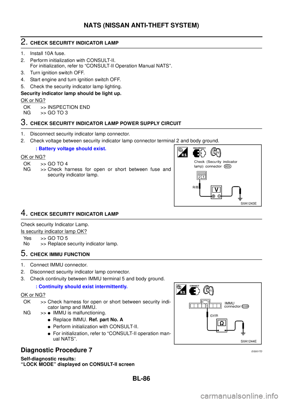
3.CHECK SECURITY INDICATOR LAMP POWER SUPPLY CIRCUIT
1. Disconnect security indicator lamp connector.
2. Check voltage between security indicator lamp connector terminal 2 and body ground.
OK or NG?
OK >> GO TO 4
NG >> Check harness for open or short between fuse and
security indicator lamp.
4.CHECK SECURITY INDICATOR LAMP
Check security Indicator Lamp.
Is security indicator lamp OK?
Yes >>GOTO5
No >> Replace security indicator lamp.
5.CHECK IMMU FUNCTION
1. Connect IMMU connector.
2. Disconnect security indicator lamp connector.
3. Check continuity between IMMU terminal 5 and body ground.
OK or NG?
OK >> Check harness for open or short between security indi-
cator lamp and IMMU.
NG >>
lIMMU is malfunctioning.
lReplace IMMU.Ref. part No. A
lPerform initialization with CONSULT-II.
lFor initialization, refer to “CONSULT-II operation man-
ual NATS”.
Diagnostic Procedure 7EIS001TD
Self-diagnostic results:
“LOCK MODE” displayed on CONSULT-II screen: Battery voltage should exist.
SIIA1243E
: Continuity should exist intermittently.
SIIA1244E
Page 831 of 3066
NATS (NISSAN ANTI-THEFT SYSTEM)
BL-87
C
D
E
F
G
H
J
K
L
MA
B
BL
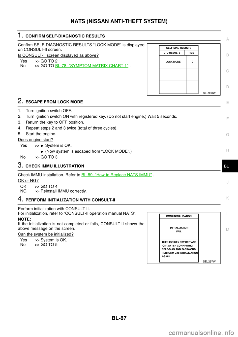
1.CONFIRM SELF-DIAGNOSTIC RESULTS
Confirm SELF-DIAGNOSTIC RESULTS “LOCK MODE” is displayed
on CONSULT-II screen.
Is CONSULT-II screen displayed as above?
Yes >>GOTO2
No >> GO TOBL-78, "
SYMPTOM MATRIX CHART 1".
2.ESCAPE FROM LOCK MODE
1. Turn ignition switch OFF.
2. Turn ignition switch ON with registered key. (Do not start engine.) Wait 5 seconds.
3. Return the key to OFF position.
4. Repeat steps 2 and 3 twice (total of three cycles).
5. Start the engine.
Does engine start?
Ye s > >lSystem is OK.
l(Now system is escaped from “LOCK MODE”.)
No >> GO TO 3
3.CHECK IMMU ILLUSTRATION
Check IMMU installation. Refer toBL-89, "
How to Replace NATS IMMU".
OK or NG?
OK >> GO TO 4
NG >> Reinstall IMMU correctly.
4.PERFORM INITIALIZATION WITH CONSULT-II
Perform initialization with CONSULT-II.
For initialization, refer to “CONSULT-II operation manual NATS”.
NOTE:
If the initialization is not completed or fails, CONSULT-II shows the
above message on the screen.
Can the system be initialized?
Ye s > > S y s t e m i s O K .
No >> GO TO 5
SEL960W
SEL297W
Page 891 of 3066
![NISSAN X-TRAIL 2003 Electronic Repair Manual TROUBLE DIAGNOSIS
BRC-23
[4WD/ABS]
C
D
E
G
H
I
J
K
L
MA
B
BRC
CAUTION:
1. Check air pressure of tire under normal condition.
2. ABS warning lamp ON/OFF timing
CONSULT-II FunctionsEFS001BH
CONSULT-II F NISSAN X-TRAIL 2003 Electronic Repair Manual TROUBLE DIAGNOSIS
BRC-23
[4WD/ABS]
C
D
E
G
H
I
J
K
L
MA
B
BRC
CAUTION:
1. Check air pressure of tire under normal condition.
2. ABS warning lamp ON/OFF timing
CONSULT-II FunctionsEFS001BH
CONSULT-II F](/manual-img/5/57402/w960_57402-890.png)
TROUBLE DIAGNOSIS
BRC-23
[4WD/ABS]
C
D
E
G
H
I
J
K
L
MA
B
BRC
CAUTION:
1. Check air pressure of tire under normal condition.
2. ABS warning lamp ON/OFF timing
CONSULT-II FunctionsEFS001BH
CONSULT-II FUNCTION APPLICATION TABLE
4WD MODE MONI-
TOROutput condition of
drive mode indicator
lamp signalEngine running, vehi-
cle stoppedUsing drive mode
change-over switchDrive mode indicator lamp
and path
IMPROPER SIZE
TIRE MONITOR (mm)Improper size tire
installed condition- 0-4,4-8Front/Rear tire size differ-
ence, wear condition
PARKING BRAKE
SWITCH (ON/OFF)Parking brake switch
operating conditionParking brake
depressedON
Parking brake switch and
harness
Parking brake not
depressedOFF
METER OUTPUT
(km/h)Output condition of
vehicle speed for
speedometerWheel stopped 0 km/h
Speed meter and harness
Vehicle runningAlmost in accordance
with the wheel speed
sensor display
ON: When ignition switch is turned ON (before engine starts) or when malfunction is
detected
OFF: After engine is started (When the system is in normal condition)
Item Self-diagnosis Data monitor Active test
FR RH SENSOR´´-
FR LH SENSOR [OPEN]´´-
RR RH SENSOR´´-
RR LH SENSOR´´-
Speed sensor´--
Stop lamp switch -´-
FR RH IN ABS SOL´´´
FR RH OUT ABS SOL´´´
FR LH IN ABS SOL´´´
FR LH OUT ABS SOL´´´
RR RH IN ABS SOL´´´
RR RH OUT ABS SOL´´´
RR LH IN ABS SOL´´´
RR LH OUT ABS SOL´´´
ABS ACTUATOR RELAY´´-
ABS MOTOR RELAY´´´
ABS warning lamp -´-
Battery voltage´´-
Control module´--
ABS MOTOR´-´
Longitudinal G -sensor´´-
4WD solenoid valve´´´
4WD actuator relay -´-
Engine speed signal -´-
Throttle position sensor´´-
Page 892 of 3066
![NISSAN X-TRAIL 2003 Electronic Repair Manual BRC-24
[4WD/ABS]
TROUBLE DIAGNOSIS
´: Applicable
–: Not applicable
SELF-DIAGNOSIS
Operation procedure
1. After obtaining customers information, performBRC-32, "Basic Inspection".
2. After turning NISSAN X-TRAIL 2003 Electronic Repair Manual BRC-24
[4WD/ABS]
TROUBLE DIAGNOSIS
´: Applicable
–: Not applicable
SELF-DIAGNOSIS
Operation procedure
1. After obtaining customers information, performBRC-32, "Basic Inspection".
2. After turning](/manual-img/5/57402/w960_57402-891.png)
BRC-24
[4WD/ABS]
TROUBLE DIAGNOSIS
´: Applicable
–: Not applicable
SELF-DIAGNOSIS
Operation procedure
1. After obtaining customer's information, performBRC-32, "Basic Inspection".
2. After turning ignition switch OFF, connect CONSULT-II connec-
tor to data link connector on vehicle.
3. Start engine and drive at Approx. 30 km/m (19 MPH) for Approx.
1minute.
4. Stop vehicle. With engine at idle, touch “START”, “ABS” and
“SELF-DIAG RESULTS” on CONSULT-II screen in this order.
CAUTION:
“ABS” may not be displayed on the system selection
screen in the following case: When “START” was touched
justafterengineisstartedorignitionswitchisturnedto
ON. In this case, repeat procedure from step 2.
5. Self-diagnosis result is displayed. (If necessary, touch “PRINT” to print self-diagnosis result.)
lIf“NO MALFUNCTION”is displayed, check ABS warning lamp. Refer toBRC-32, "BASIC INSPECTION
3 ABS/4WD WARNING LAMP INSPECTION".
6. Check the faulty part indicated by the chart to repair or replace.
7. Start engine and drive at Approx. 30 km/m (19 MPH) for Approx. 1 minute.
CAUTION:
lCheck again to make sure that there is NO FAILURE on other parts.
lIf wheel speed sensor [SHORT] is detected, ABS warning lamp does not turn off until following
conditions: Vehicle is driven at Approx. 30km/h for Approx. 1 minute, even in normal conditions.
8. Turn OFF ignition switch to prepare for erasing memory.
9. Start engine. Touch “START,” “ABS,” “SELF-DIAG RESULTS,” and “ERASE MEMORY” on CONSULT-II
screen in this order to erase fault memory.
CAUTION:
If memory cannot be erased, proceed to 6.
10. Drive at Approx. 30 km/m (19 MPH) for Approx. 1 minute. Be sure ABS warning lamp is OFF.
Improper size tire monitor -´-
4WD mode monitor -´-
4WD warning lamp -´-
Stop lamp switch -´-
Parking brake switch -´-
Meter output -´- Item Self-diagnosis Data monitor Active test
PBIA0153E