2003 NISSAN X-TRAIL display
[x] Cancel search: displayPage 956 of 3066
![NISSAN X-TRAIL 2003 Electronic Repair Manual BRC-88
[ESP/TCS/ABS]
TROUBLE DIAGNOSIS
For Correct and Quick Diagnosis
EFS001A8
PRECAUTIONS FOR TROUBLE DIAGNOSIS
lBefore performing the trouble diagnosis, always read theGI-3, "PRECAUTIONS"to confirm NISSAN X-TRAIL 2003 Electronic Repair Manual BRC-88
[ESP/TCS/ABS]
TROUBLE DIAGNOSIS
For Correct and Quick Diagnosis
EFS001A8
PRECAUTIONS FOR TROUBLE DIAGNOSIS
lBefore performing the trouble diagnosis, always read theGI-3, "PRECAUTIONS"to confirm](/manual-img/5/57402/w960_57402-955.png)
BRC-88
[ESP/TCS/ABS]
TROUBLE DIAGNOSIS
For Correct and Quick Diagnosis
EFS001A8
PRECAUTIONS FOR TROUBLE DIAGNOSIS
lBefore performing the trouble diagnosis, always read theGI-3, "PRECAUTIONS"to confirm the general
precautions.
lAfter replacement of ESP/TCS/ABS control unit, steering angle sensor, steering parts, suspension parts,
or tires, and adjustment of alignment, always adjust the neutral position of steering angle sensor before
driving.
lWhen the ESP/TCS/ABS control unit is replaced, check that the label on the computer unit is identical
color.
lAfter completing the trouble diagnosis, always erase the malfunctioning memory.BRC-77, "Functions of
CONSULT-II"
lWhen inspection of the continuity or voltage between units is performed, check the connector terminals for
disconnection, looseness, bend, or collapse. If any malfunction is detected, repair or replace the applica-
ble part.
lIntermittent problems may be caused by a malfunction on harness, connector, or terminal. Move the har-
nesses, harness connectors, or terminals by hand to make sure that there is no contact malfunction.
lIf a circuit tester is used for the check, be careful not to forcibly extend any connector terminal.
lFor self-diagnosis, active test, and work support of ESP/TCS/ABS control unit with CONSULT-II, stop and
connect CONSULT-II and select²ABS².
lCONSULT-II self-diagnosis results are displayed without regard to occurrence timing. In some case, the
later ones (timing value is small) appear on the next screen.
lWhile the self-diagnosis results of CONSULT-II shows a malfunction, if CONSULT-II active test is per-
formed, an engine system malfunction may be indicated. In this case, start the engine to resume the nor-
mal screen.
lESP/TCS/ABS system electronically controls the brake operation and engine output. The following symp-
toms may be caused by the normal operations.
Symptom Symptom description Result
Motor operation noiseDuring ESP, TCS, or ABS operation, sometimes a faint noise can be
heard. This is a motor operation noise in the ESP/TCS/ABS actuator.
Normal
Just after the engine starts, the motor operating noise may be heard.
This is a normal status of the system operation check.
System operation check
noiseWhen the engine starts, a²click²noise may be heard from the engine
compartment. This is a normal status of the system operation check.Normal
ESP/TCS operation
(SLIP lamp ON)When the vehicle is passing through a road where the surface friction
coefficient varies or the wheel speed changes suddenly by downshifting
or depressing of the accelerator pedal fully, TCS may be activated tem-
porarily.
Normal
Cancel the ESP/TCS
function for the
inspection on a chas-
sis dynamometer. Before the speedometer inspection, turn ESP OFF switch off to cancel
the ESP/TCS function.
When the accelerator pedal is depressed on a chassis dynamometer,
the vehicle speed will not increase. This is not malfunction, because
TCS is activated by the wheel speed difference between front and rear.
The warning lamp may also illuminate to show²sensor system failure²in
this case. This is not malfunction either, because the stationary front
wheels are detected. Restart the engine, and drive the vehicle at 30 km/
h or higher to check that the warning lamp no longer illuminates.
ABS operation (Longer stop-
ping distance)The stopping distance may be longer for the vehicles with ABS when the
vehicle is driver on snowy and rough road. When driving on the road like
that, slow down the speed.Normal
Sluggish feelDepending on road circumstances, the driver may have a sluggish feel.
This is not abnormal, because the optimum traction has the highest pri-
ority (safety first) by TCS operation. Sometimes the driver has a slight
sluggish feel against the substantial accelerator pedal operation.Normal
Page 974 of 3066
![NISSAN X-TRAIL 2003 Electronic Repair Manual BRC-106
[ESP/TCS/ABS]
TROUBLE DIAGNOSIS
5.ESP/TCS/ABS CONTROL UNIT POWER SUPPLY CIRCUIT INSPECTION 2
1. Check the fuse 10A.
2. Check for continuity between the battery positive terminal and
the ESP/TC NISSAN X-TRAIL 2003 Electronic Repair Manual BRC-106
[ESP/TCS/ABS]
TROUBLE DIAGNOSIS
5.ESP/TCS/ABS CONTROL UNIT POWER SUPPLY CIRCUIT INSPECTION 2
1. Check the fuse 10A.
2. Check for continuity between the battery positive terminal and
the ESP/TC](/manual-img/5/57402/w960_57402-973.png)
BRC-106
[ESP/TCS/ABS]
TROUBLE DIAGNOSIS
5.ESP/TCS/ABS CONTROL UNIT POWER SUPPLY CIRCUIT INSPECTION 2
1. Check the fuse 10A.
2. Check for continuity between the battery positive terminal and
the ESP/TCS/ABS control unit connector.
Is inspection result OK?
YES >> Check the battery for a loose terminal and low voltage or the alternator for abnormality.
NO >>
lReplace the fuse 10A.
lHarness disconnection
Inspection 12 When “EMERGENCY BRAKE” is indicated in the Self-Diagnosis
Results
EFS001AO
Inspection procedure
1.SELF-DIAGNOSIS RESULT CHECK
Check the self-diagnosis results.
When any items other than²EMERGENCY BRAKE²is displayed in the self-diagnosis results, follow the
instructions below.
CAUTION:
²EMERGENCY BRAKE²is indicated when the control unit itself is detected internal error. If this display
item was indicated, replace the control unit.
Is
²EMERGENCY BRAKE²is indicated in the self-diagnosis results?
>> Replace the ESP/TCS/ABS control unit, and perform the self-diagnosis again.
Inspection 13 When “ST ANG SEN SIGNAL” is Indicated in the Self-Diagnosis
Results
EFS001AP
Inspection procedure
1.SELF-DIAGNOSIS RESULT CHECK 1
Check the self-diagnosis results.
When any items other than
²ST ANGLE SEN SIGNAL²is displayed in the self-diagnosis results:
YES >> Check and repair the applicable items. Perform the self-diagnosis again.
NO >> Perform the steering angle sensor neutral position adjustment. GO TO 2.
SFIA0387E
ESP/TCS/ABS control unit
(Vehicle-side connector)Battery terminal Continuity
1 positive Yes
Self-diagnosis results
CONSULT-II indication item
EMERGENCY BRAKE
Self-diagnosis results
CONSULT-II indication item
ST ANGLE SEN SIGNAL
Page 984 of 3066
![NISSAN X-TRAIL 2003 Electronic Repair Manual BRC-116
[ESP/TCS/ABS]
TROUBLE DIAGNOSIS
Symptom 7: SLIP Indicator Lamp Does Not Illuminate
EFS001AY
Inspection procedure
1.SLIP INDICATOR LAMP BURNED-OUT BULB INSPECTION
Check for continuity between t NISSAN X-TRAIL 2003 Electronic Repair Manual BRC-116
[ESP/TCS/ABS]
TROUBLE DIAGNOSIS
Symptom 7: SLIP Indicator Lamp Does Not Illuminate
EFS001AY
Inspection procedure
1.SLIP INDICATOR LAMP BURNED-OUT BULB INSPECTION
Check for continuity between t](/manual-img/5/57402/w960_57402-983.png)
BRC-116
[ESP/TCS/ABS]
TROUBLE DIAGNOSIS
Symptom 7: SLIP Indicator Lamp Does Not Illuminate
EFS001AY
Inspection procedure
1.SLIP INDICATOR LAMP BURNED-OUT BULB INSPECTION
Check for continuity between the power supply terminal of meter and terminal of ABS warning lamp.
Is inspection result OK?
OK >> GO TO 2.
NG >> Circuit malfunction in SLIP indicator lamp or combination meter
2.SLIP INDICATOR LAMP POWER CIRCUIT INSPECTION
Disconnect the meter connector. Check that the voltage between the vehicle-side harness terminal and body
ground is battery voltage (Approx. 12V).
Is inspection result OK?
YES >> GO TO 3.
NO >>
lFuse inspection
lInspection for harness and connectors between fuse block and meter
lCheck the power supply circuit (battery and ignition switch circuit).
3.SLIP INDICATOR LAMP HARNESS INSPECTION
1. Disconnect connectors for the ESP/TCS/ABS control unit and meter vehicle-side harness.
2. Check the harness between the meter and the ESP/TCS/ABS control unit for an open/shorted circuit.
Is inspection result OK?
OK >> GO TO 4.
NG >> Repair or replace the disconnected harness.
4.SLIP INDICATOR LAMP CONNECTOR INSPECTION
Check connectors for the ESP/TCS/ABS control unit and meter vehicle-side harness.
Is inspection result OK?
YES >> Connect connectors, and perform the self-diagnosis. The vehicle harness has the intermediate
connector. Refer to the vehicle wiring diagram, always check it.
NG >> Repair or replace the disconnected connector.
Symptom 8: During ESP/TCS/ABS Control, Vehicle Behavior is Jerky.EFS001AZ
Inspection procedure
1.ENGINE SPEED SIGNAL INSPECTION
Perform²DATA MONITOR²with CONSULT-II for the ESP/TCS/ABS control unit.
Is the engine speed at idle 400 rpm or higher?
YES >> Normal
NO >> GO TO 2.
2.SELF-DIAGNOSIS RESULT CHECK 1
Perform the ESP/TCS/ABS control unit self-diagnosis.
Is the self-diagnosis results displayed?
YES >> After checking and repairing the applicable item, perform the ESP/TCS/ABS control unit self-
diagnosis again.
NO >> GO TO 3.
Page 985 of 3066
![NISSAN X-TRAIL 2003 Electronic Repair Manual TROUBLE DIAGNOSIS
BRC-117
[ESP/TCS/ABS]
C
D
E
G
H
I
J
K
L
MA
B
BRC
3.ECM SELF-DIAGNOSIS RESULT CHECK
Perform the ECM self-diagnosis.
Is the self-diagnosis results indicated?
YES >> Repair or replace t NISSAN X-TRAIL 2003 Electronic Repair Manual TROUBLE DIAGNOSIS
BRC-117
[ESP/TCS/ABS]
C
D
E
G
H
I
J
K
L
MA
B
BRC
3.ECM SELF-DIAGNOSIS RESULT CHECK
Perform the ECM self-diagnosis.
Is the self-diagnosis results indicated?
YES >> Repair or replace t](/manual-img/5/57402/w960_57402-984.png)
TROUBLE DIAGNOSIS
BRC-117
[ESP/TCS/ABS]
C
D
E
G
H
I
J
K
L
MA
B
BRC
3.ECM SELF-DIAGNOSIS RESULT CHECK
Perform the ECM self-diagnosis.
Is the self-diagnosis results indicated?
YES >> Repair or replace the camshaft position sensor system.
NO >> GO TO 4.
4.SELF-DIAGNOSIS RESULT 2
Disconnect connectors for the ESP/TCS/ABS control unit and ECM, and reconnect them correctly to perform
the self-diagnosis again.
Is inspection result OK?
OK >> GO TO 5.
NG >> Connector malfunction. Repair or replace the connector.
5.SELF-DIAGNOSIS RESULT CHECK 3
Perform the 4WD control unit self-diagnosis.
Is inspection result OK?
OK >> GO TO 6.
NG >> Repair or replace the applicable part.
6.SELF-DIAGNOSIS RESULT CHECK 4
Perform the ESP/TCS/4WD control unit self-diagnosis again.
Is the self-diagnosis results displayed?
YES >> Repair or replace the applicable item.
NO >> GO TO 7.
7.CIRCUIT CHECK BETWEEN ESP/TCS/ABS CONTROL UNIT AND ECM
1. Disconnect connectors for the ESP/TCS/ABS control unit and ECM.
2. Check the engine speed signal harness between the ESP/TCS/ABS control unit and ECM for an open/
shorted circuit.
3. Check connectors for the ESP/TCS/ABS control unit and ECM.
Is inspection result OK?
OK >> Inspection End
NG >> Repair or replace the applicable item and perform the ESP/TCS/ABS control unit self-diagnosis
again.
Page 1055 of 3066

DI-1
DRIVER INFORMATION SYSTEM
K ELECTRICAL
CONTENTS
C
D
E
F
G
H
I
J
L
M
SECTION
A
B
DI
DRIVER INFORMATION SYSTEM
PRECAUTIONS .......................................................... 3
Precautions for Supplemental Restraint System
(SRS) “AIR BAG” and “SEAT BELT PRE-TEN-
SIONER” .................................................................. 3
Wiring Diagrams and Trouble Diagnosis .................. 3
COMBINATION METERS (LHD MODELS) ................ 4
System Description .................................................. 4
UNIFIED CONTROL METER ................................ 4
HOW TO CHANGE THE DISPLAY FOR ODO/
TRIP METER ........................................................ 4
POWER SUPPLY AND GROUND CIRCUIT ........ 4
WATER TEMPERATURE GAUGE ........................ 4
TACHOMETER ..................................................... 5
FUEL GAUGE ....................................................... 5
SPEEDOMETER ................................................... 5
Component Parts and Harness Connector Location..... 5
Combination Meter ................................................... 6
CHECK .................................................................. 6
Schematic ................................................................ 7
Wiring Diagram — METER — .................................. 8
Meter/Gauge Operation and Odo/Trip Meter Seg-
ment Check in Diagnosis Mode ............................. 10
DIAGNOSIS FUNCTION ..................................... 10
HOW TO ALTERNATE DIAGNOSIS MODE ....... 10
Trouble Diagnoses ................................................. 10
PRELIMINARY CHECK ...................................... 10
SYMPTOM CHART ..............................................11
Power Supply and Ground Circuit Check ............... 12
Inspection/Engine Speed Signal ............................ 12
Inspection/Water Temperature Gauge /Gasoline
Engine Models ....................................................... 13
Inspection/Water Temperature Gauge (Diesel
Engine Models) ...................................................... 13
Inspection/Vehicle speed signal ............................. 14
Inspection/Fuel Level Sensor Unit ......................... 15
FUEL LEVEL SENSOR UNIT ............................. 15
LOW-FUEL WARNING LAMP ............................. 15
The Fuel Gauge Pointer Fluctuates·Indicator
Wrong Value·or Varies. ........................................... 17
The Fuel Gauge Does Not Move to F-position. ...... 18The Fuel Gauge Does Not Work. ........................... 18
Low Fuel Warning Lamp Illuminate or Not Illuminate... 19
Electrical Components Inspection .......................... 19
FUEL LEVEL SENSOR UNIT CHECK / GASO-
LINE ENGINE MODELS ..................................... 19
FUEL LEVEL SENSOR UNIT CHECK / DIESEL
ENGINE MODELS EXCEPT FOR NORTHERN
EUROPE ............................................................. 19
FUEL LEVEL SENSOR UNIT CHECK / DIESEL
ENGINE MODELS FOR NORTHERN EUROPE... 20
THERMAL TRANSMITTER CHECK ................... 20
Removal and Installation for Combination Meter .... 21
Disassembly and Assembly for Combination Meter... 21
COMBINATION METERS (RHD MODELS) .............. 22
System Description ................................................. 22
UNIFIED CONTROL METER .............................. 22
HOW TO CHANGE THE DISPLAY FOR ODO/
TRIP METER ....................................................... 22
POWER SUPPLY AND GROUND CIRCUIT ....... 22
WATER TEMPERATURE GAUGE ...................... 22
TACHOMETER .................................................... 23
FUEL GAUGE ..................................................... 23
SPEEDOMETER ................................................. 23
Component Parts and Harness Connector Location... 23
Combination Meter ................................................. 24
CHECK ................................................................ 24
Schematic ............................................................... 25
Wiring Diagram — METER — ................................ 26
Meter/Gauge Operation and Odo/Trip Meter Seg-
ment Check in Diagnosis Mode .............................. 28
DIAGNOSIS FUNCTION ..................................... 28
HOW TO ALTERNATE DIAGNOSIS MODE ....... 28
Trouble Diagnoses ................................................. 28
PRELIMINARY CHECK ....................................... 28
SYMPTOM CHART ............................................. 29
Power Supply and Ground Circuit Check ............... 30
Inspection/Engine Speed Signal ............................. 30
Inspection/Water Temperature Gauge /Gasoline
Engine Models ........................................................ 31
Inspection/Water Temperature Gauge (Diesel
Page 1058 of 3066

DI-4
COMBINATION METERS (LHD MODELS)
COMBINATION METERS (LHD MODELS)
PFP:24810
System DescriptionEKS002Z7
UNIFIED CONTROL METER
lSpeedometer, odo/trip meter, tachometer, fuel gauge and water temperature gauge are controlled totally
by control unit built-in combination meter.
lDigital meter is adopted for odo/trip meter.*
*The record of the odo meter is kept even if the battery cable is disconnected. The record of the trip meter
is erased when the battery cable is disconnected.
lOdo/trip meter segment can be checked in diagnosis mode.
lMeter/gauge can be checked in diagnosis mode.
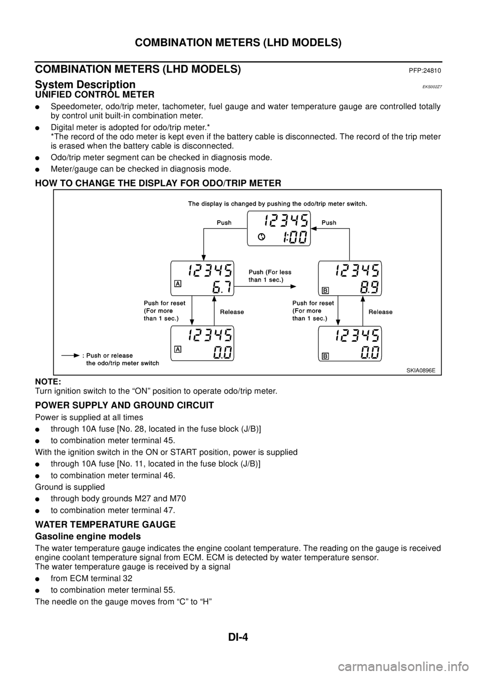
HOW TO CHANGE THE DISPLAY FOR ODO/TRIP METER
NOTE:
Turn ignition switch to the “ON” position to operate odo/trip meter.
POWER SUPPLY AND GROUND CIRCUIT
Power is supplied at all times
lthrough 10A fuse [No. 28, located in the fuse block (J/B)]
lto combination meter terminal 45.
With the ignition switch in the ON or START position, power is supplied
lthrough 10A fuse [No. 11, located in the fuse block (J/B)]
lto combination meter terminal 46.
Ground is supplied
lthrough body grounds M27 and M70
lto combination meter terminal 47.
WATER TEMPERATURE GAUGE
Gasoline engine models
The water temperature gauge indicates the engine coolant temperature. The reading on the gauge is received
engine coolant temperature signal from ECM. ECM is detected by water temperature sensor.
The water temperature gauge is received by a signal
lfrom ECM terminal 32
lto combination meter terminal 55.
The needle on the gauge moves from “C” to “H”
SKIA0896E
Page 1059 of 3066

COMBINATION METERS (LHD MODELS)
DI-5
C
D
E
F
G
H
I
J
L
MA
B
DI
Diesel engine models
The water temperature gauge indicates the engine coolant temperature. The reading on the gauge is based
on the resistance of the thermal transmitter.
As the temperature of the coolant increases, the resistance of the thermal transmitter decreases. A variable
ground is supplied to terminal 55 of the combination meter for the water temperature gauge. The needle on
the gauge moves from “C” to “H”.
TACHOMETER
The tachometer indicates engine speed in revolutions per minute (rpm).
The tachometer is regulated by a signal
lfrom terminal 36 (Gasoline engine models) or D1 (Diesel engine models) of the ECM
lto combination meter terminal 54 for the tachometer.
FUEL GAUGE
The fuel gauge indicates the approximate fuel level in the fuel tank.
The fuel gauge is regulated by a variable ground signal supplied
lfrom body grounds, B8 and B18
lthrough terminal 1 and 3 of the Sub fuel level sensor unit and
lthrough terminal 4 and 1 of the fuel level sensor unit
lto combination meter terminal 51 for the fuel gauge.
SPEEDOMETER
The combination meter provides a voltage signal to the vehicle speed signal from 4WD/ABS control unit (with-
out ESP) or 4WD control unit (with ESP).
The voltage is supplied
lfrom combination meter terminal 42 for the speedometer
lto terminal 20 of 4WD/ABS control unit (without ESP) or 4WD control unit (without ESP).
The speedometer converts the voltage into the vehicle speed displayed.
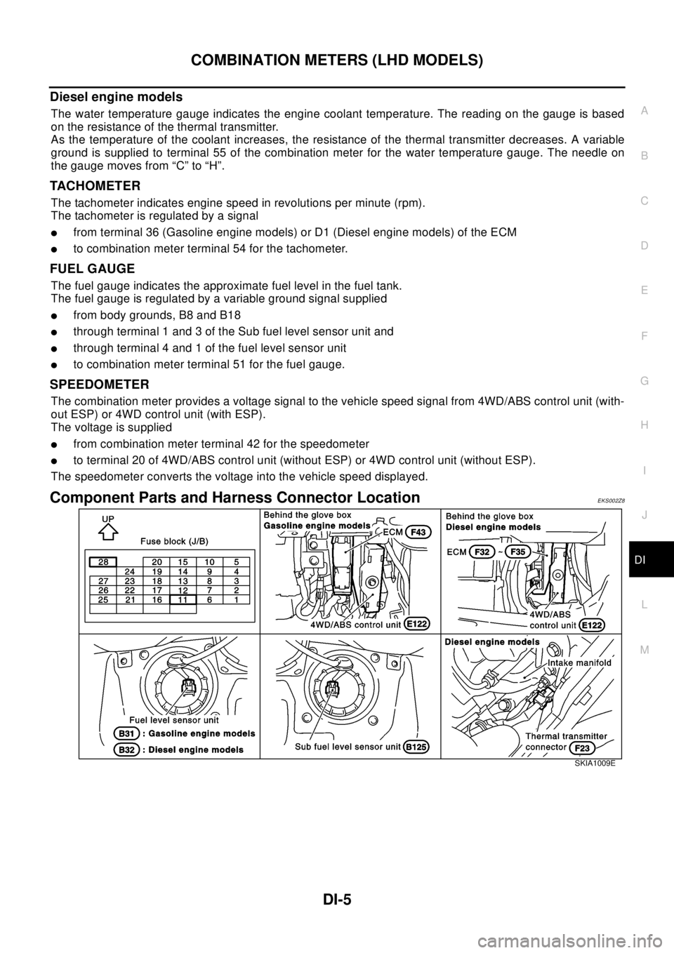
Component Parts and Harness Connector LocationEKS002Z8
SKIA1009E
Page 1076 of 3066

DI-22
COMBINATION METERS (RHD MODELS)
COMBINATION METERS (RHD MODELS)
PFP:24810
System DescriptionEKS0030H
UNIFIED CONTROL METER
lSpeedometer, odo/trip meter, tachometer, fuel gauge and water temperature gauge are controlled totally
by control unit built-in combination meter.
lDigital meter is adopted for odo/trip meter.*
*The record of the odo meter is kept even if the battery cable is disconnected. The record of the trip meter
is erased when the battery cable is disconnected.
lOdo/trip meter segment can be checked in diagnosis mode.
lMeter/gauge can be checked in diagnosis mode.
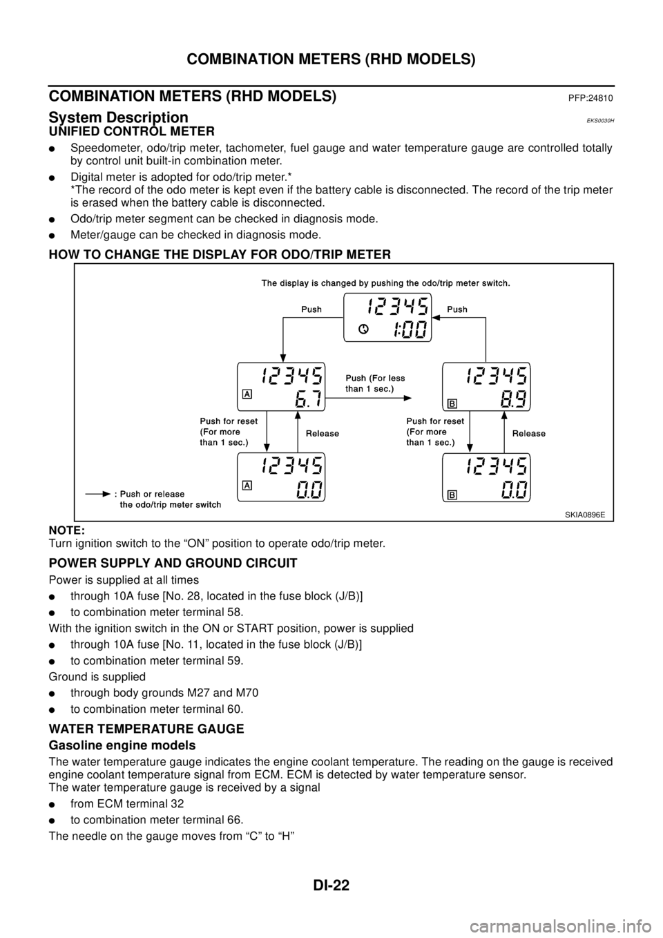
HOW TO CHANGE THE DISPLAY FOR ODO/TRIP METER
NOTE:
Turn ignition switch to the “ON” position to operate odo/trip meter.
POWER SUPPLY AND GROUND CIRCUIT
Power is supplied at all times
lthrough 10A fuse [No. 28, located in the fuse block (J/B)]
lto combination meter terminal 58.
With the ignition switch in the ON or START position, power is supplied
lthrough 10A fuse [No. 11, located in the fuse block (J/B)]
lto combination meter terminal 59.
Ground is supplied
lthrough body grounds M27 and M70
lto combination meter terminal 60.
WATER TEMPERATURE GAUGE
Gasoline engine models
The water temperature gauge indicates the engine coolant temperature. The reading on the gauge is received
engine coolant temperature signal from ECM. ECM is detected by water temperature sensor.
The water temperature gauge is received by a signal
lfrom ECM terminal 32
lto combination meter terminal 66.
The needle on the gauge moves from “C” to “H”
SKIA0896E