2003 NISSAN X-TRAIL steering
[x] Cancel search: steeringPage 1 of 3066

MODEL T30 SERIES
2001 NISSAN EUROPE N.V.
All rights reserved. No part of this Electronic Service Manual may be reproduced or stored in a retrieval system, or transmitted in any
form, or by any means, electronic, mechanical, photocopying, recording or otherwise, without the prior written permission of Nissan
Europe N.V., Paris, France.
A GENERAL INFORMATION
B ENGINE
C TRANSMISSION/
TRANSAXLE
D DRIVELINE/AXLE
E SUSPENSION
F BRAKES
G STEERING
H RESTRAINTS
I BODY
J AIR CONDITIONER
K ELECTRICAL
L MAINTENANCE
M INDEXGI General Information
EM Engine Mechanical
LU Engine Lubrication System
CO Engine Cooling System
EC Engine Control System
FL Fuel System
EX Exhaust System
ACC Accelerator Control System
CL Clutch
MT Manual Transaxle
AT Automatic Transaxle
TF Transfer
PR Propeller Shaft
RFD Rear Final Drive
FAX Front Axle
RAX Rear Axle
FSU Front Suspension
RSU Rear Suspension
WT Road Wheels & Tires
BR Brake System
PB Parking Brake System
BRC Brake Control System
PS Power Steering System
SB Seat Belts
SRS Supplemental Restraint System (SRS)
BL Body, Lock & Security System
GW Glasses, Window System & Mirrors
RF Roof
EI Exterior & Interior
IP Instrument Panel
SE Seat
ATC Automatic Air Conditioner
MTC Manual AIr Conditioner
SC Starting & Charging System
LT Lighting System
DI Driver Information System
WW Wiper, Washer & Horn
BCS Body Control System
LAN LAN System
AV Audio, Visual & Telephone System
PG Power Supply, Ground & Circuit Elements
MA Maintenance
IDX Alphabetical Index
QUICK REFERENCE INDEX
A
B
C
D
E
F
G
H
I
J
K
L
M
Page 459 of 3066
![NISSAN X-TRAIL 2003 Electronic Repair Manual KEY INTERLOCK CABLE
AT-453
[ALL]
D
E
F
G
H
I
J
K
L
MA
B
AT
2. Remove lock plate from steering lock assembly and remove key
interlock cable.
InstallationECS0040B
1. Turn ignition key to lock position.
NISSAN X-TRAIL 2003 Electronic Repair Manual KEY INTERLOCK CABLE
AT-453
[ALL]
D
E
F
G
H
I
J
K
L
MA
B
AT
2. Remove lock plate from steering lock assembly and remove key
interlock cable.
InstallationECS0040B
1. Turn ignition key to lock position.](/manual-img/5/57402/w960_57402-458.png)
KEY INTERLOCK CABLE
AT-453
[ALL]
D
E
F
G
H
I
J
K
L
MA
B
AT
2. Remove lock plate from steering lock assembly and remove key
interlock cable.
InstallationECS0040B
1. Turn ignition key to lock position.
2. Set A/T selector lever to P position.
3. Set key interlock cable to steering lock assembly and install lock
plate.
4. Clamp cable to steering column and fix to control cable with
band.
5. Insert interlock rod into adjuster holder.
6. Install casing cap to bracket.
7. Move slider in order to fix adjuster holder to interlock rod.
SAT854J
SAT854J
SAT804E
SAT805E
Page 693 of 3066
HEATER & COOLING UNIT ASSEMBLY
ATC-115
C
D
E
F
G
H
I
K
L
MA
B
AT C
HEATER & COOLING UNIT ASSEMBLYPFP:27110
Removal and InstallationEJS000UT
REMOVAL
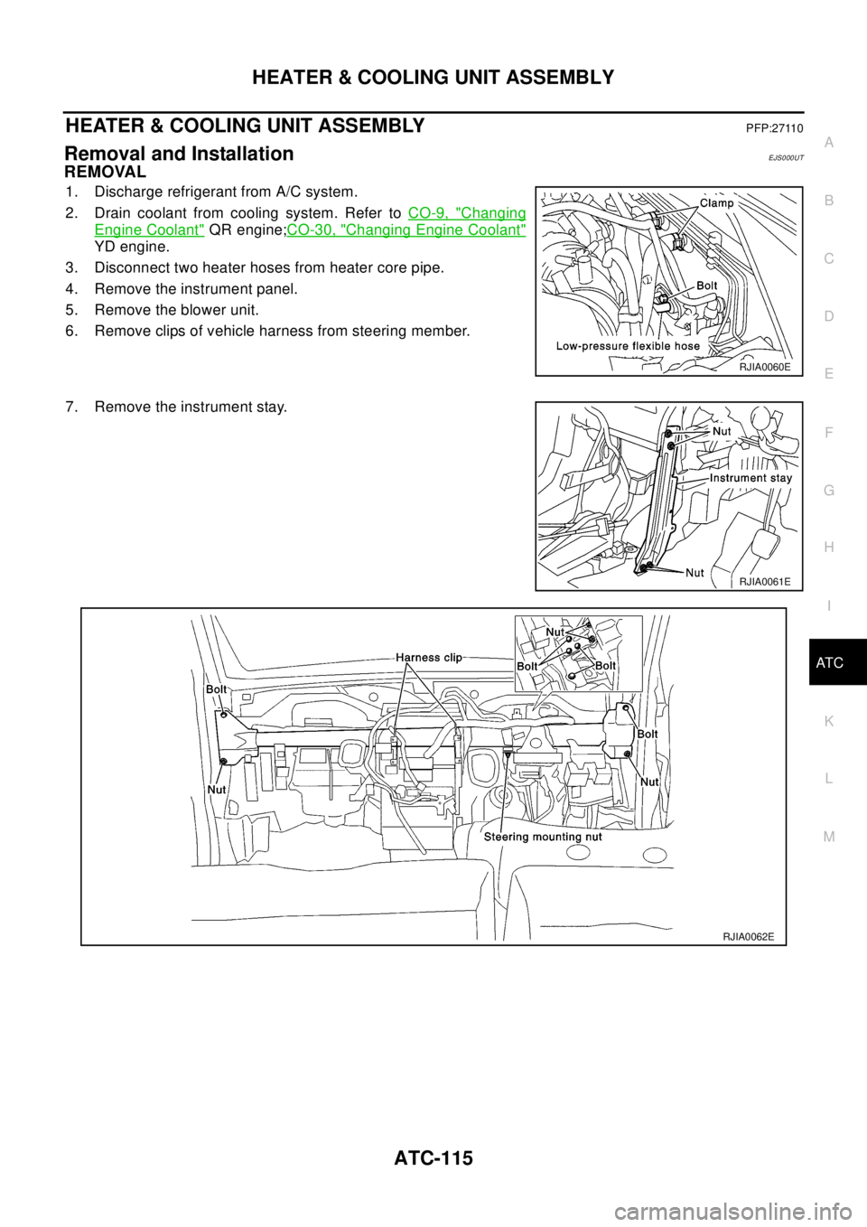
1. Discharge refrigerant from A/C system.
2. Drain coolant from cooling system. Refer toCO-9, "
Changing
Engine Coolant"QR engine;CO-30, "Changing Engine Coolant"
YD engine.
3. Disconnect two heater hoses from heater core pipe.
4. Remove the instrument panel.
5. Remove the blower unit.
6. Remove clips of vehicle harness from steering member.
7. Remove the instrument stay.
RJIA0060E
RJIA0061E
RJIA0062E
Page 694 of 3066
ATC-116
HEATER & COOLING UNIT ASSEMBLY
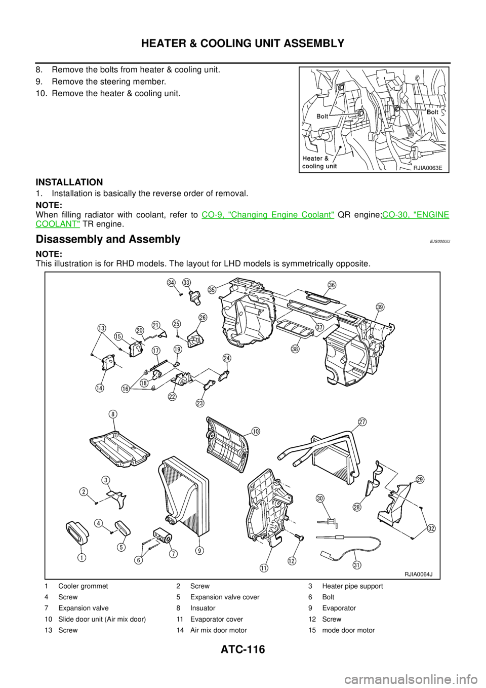
8. Remove the bolts from heater & cooling unit.
9. Remove the steering member.
10. Remove the heater & cooling unit.
INSTALLATION
1. Installation is basically the reverse order of removal.
NOTE:
When filling radiator with coolant, refer toCO-9, "
Changing Engine Coolant"QR engine;CO-30, "ENGINE
COOLANT"TR engine.
Disassembly and AssemblyEJ S00 0UU
NOTE:
This illustration is for RHD models. The layout for LHD models is symmetrically opposite.
RJIA0063E
1 Cooler grommet 2 Screw 3 Heater pipe support
4 Screw 5 Expansion valve cover 6 Bolt
7 Expansion valve 8 Insuator 9 Evaporator
10 Slide door unit (Air mix door) 11 Evaporator cover 12 Screw
13 Screw 14 Air mix door motor 15 mode door motor
RJIA0064J
Page 839 of 3066
NOISE, VIBRATION, AND HARSHNESS (NVH) TROUBLESHOOTING
BR-5
C
D
E
G
H
I
J
K
L
MA
B
BR
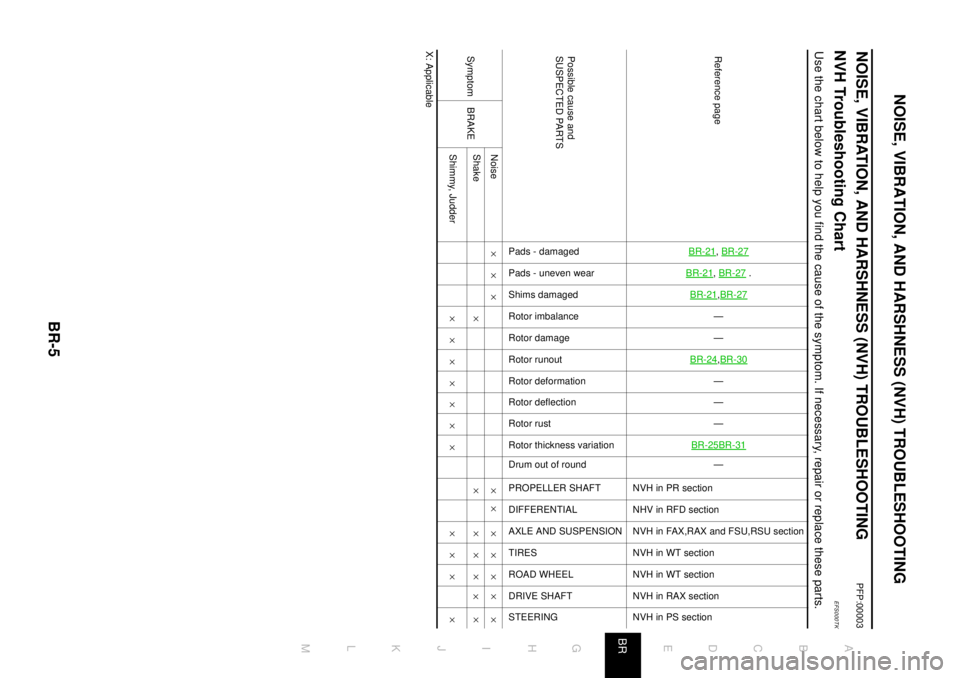
NOISE, VIBRATION, AND HARSHNESS (NVH) TROUBLESHOOTINGPFP:00003
NVH Troubleshooting ChartEFS000TK
Use the chart below to help you find the cause of the symptom. If necessary, repair or replace these parts.
X: ApplicableReference page
BR-21
,BR-27
BR-21
,BR-27
.
BR-21
,BR-27—
—
BR-24,BR-30—
—
—
BR-25BR-31—
NVHinPRsection
NHV in RFD section
NVH in FAX,RAX and FSU,RSU section
NVH in WT section
NVH in WT section
NVH in RAX section
NVH in PS section
Possible cause and
SUSPECTED PARTS
Pads - damaged
Pads - uneven wear
Shims damaged
Rotor imbalance
Rotor damage
Rotor runout
Rotor deformation
Rotor deflection
Rotor rust
Rotor thickness variation
Drum out of round
PROPELLER SHAFT
DIFFERENTIAL
AXLE AND SUSPENSION
TIRES
ROAD WHEEL
DRIVE SHAFT
STEERING
Symptom BRAKENoise´´´ ´´ ´´´
´´
Shake´ ´ ´´´
´´
Shimmy, Judder´´´´´´´ ´´´ ´
Page 841 of 3066
BRAKE PEDAL
BR-7
C
D
E
G
H
I
J
K
L
MA
B
BR
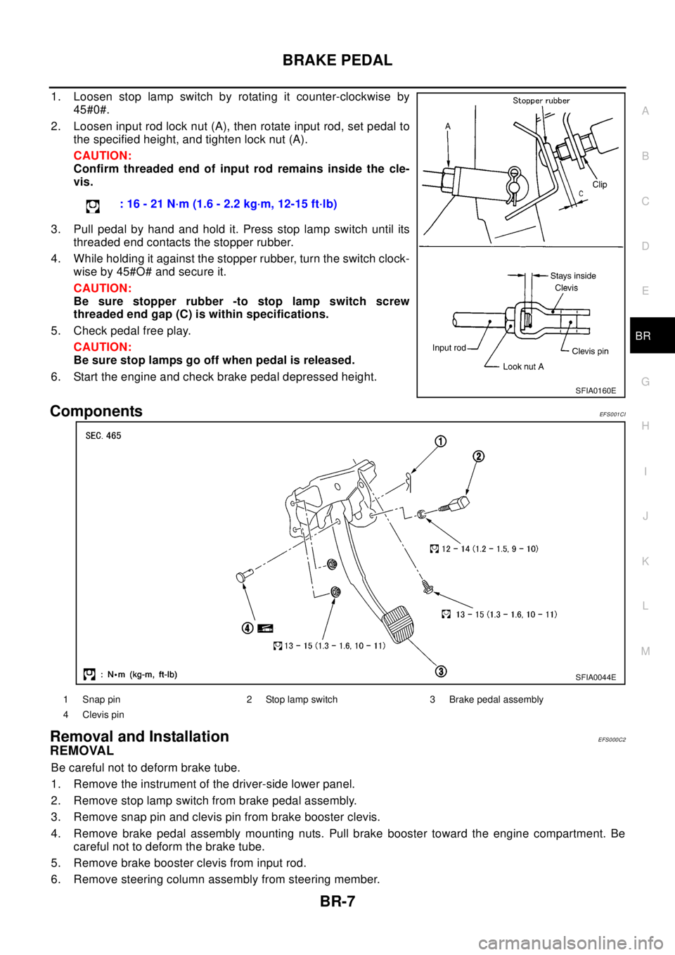
1. Loosen stop lamp switch by rotating it counter-clockwise by
45#0#.
2. Loosen input rod lock nut (A), then rotate input rod, set pedal to
the specified height, and tighten lock nut (A).
CAUTION:
Confirm threaded end of input rod remains inside the cle-
vis.
3. Pull pedal by hand and hold it. Press stop lamp switch until its
threaded end contacts the stopper rubber.
4. While holding it against the stopper rubber, turn the switch clock-
wise by 45#O# and secure it.
CAUTION:
Be sure stopper rubber -to stop lamp switch screw
threaded end gap (C) is within specifications.
5. Check pedal free play.
CAUTION:
Be sure stop lamps go off when pedal is released.
6. Start the engine and check brake pedal depressed height.
ComponentsEF S0 01 CI
Removal and InstallationEFS000C2
REMOVAL
Be careful not to deform brake tube.
1. Remove the instrument of the driver-side lower panel.
2. Remove stop lamp switch from brake pedal assembly.
3. Remove snap pin and clevis pin from brake booster clevis.
4. Remove brake pedal assembly mounting nuts. Pull brake booster toward the engine compartment. Be
careful not to deform the brake tube.
5. Remove brake booster clevis from input rod.
6. Remove steering column assembly from steering member.: 16 - 21 N·m (1.6 - 2.2 kg·m, 12-15 ft·lb)
SFIA0160E
SFIA0044E
1 Snap pin 2 Stop lamp switch 3 Brake pedal assembly
4 Clevis pin
Page 842 of 3066
BR-8
BRAKE PEDAL
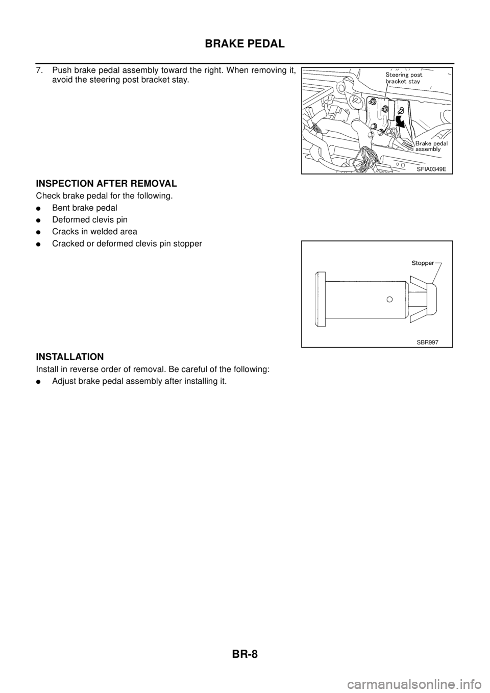
7. Push brake pedal assembly toward the right. When removing it,
avoid the steering post bracket stay.
INSPECTION AFTER REMOVAL
Check brake pedal for the following.
lBent brake pedal
lDeformed clevis pin
lCracks in welded area
lCracked or deformed clevis pin stopper
INSTALLATION
Install in reverse order of removal. Be careful of the following:
lAdjust brake pedal assembly after installing it.
SFIA0349E
SBR997
Page 869 of 3066

BRC-1
BRAKE CONTROL SYSTEM
F BRAKES
CONTENTS
C
D
E
G
H
I
J
K
L
M
SECTION
A
B
BRC
BRAKE CONTROL SYSTEM
4WD/ABS
PRECAUTIONS .......................................................... 4
Precautions for brake system ................................... 4
Precautions for brake control ................................... 4
PREPARATION ........................................................... 5
Special Service Tools ............................................... 5
ALL MODE 4X4 SYSTEM .......................................... 6
System Description .................................................. 6
ABS FUNCTION ................................................... 6
4WD FUNCTION ................................................... 6
Control System Diagram .......................................... 6
TROUBLE DIAGNOSIS .............................................. 7
Fail-safe Function ..................................................... 7
How to Proceed with Trouble Diagnosis .................. 7
BASIC CONCEPT ................................................. 7
DIAGNOSIS FLOW ............................................... 8
ASKING COMPLAINTS ........................................ 9
TROUBLE DIAGNOSIS SHEET - EXAMPLE ....... 9
Component Parts Location ..................................... 10
Schematic ...............................................................11
Wiring Diagram — ABS — ..................................... 12
Trouble Diagnosis Chart by Symptom .................... 18
4WD/ABS Control Unit Input/Output Signal Stan-
dard ........................................................................ 19
4WD/ABS CONTROL UINT CONNECTOR TER-
MINAL ARRANGEMENT .................................... 19
REFERENCE STANDARD TABLE ..................... 19
CONSULT-II Functions ........................................... 23
CONSULT-II FUNCTION APPLICATION TABLE... 23
SELF-DIAGNOSIS .............................................. 24
DATA MONITOR ................................................. 26
ACTIVE TEST ..................................................... 29
Component Inspection ........................................... 30
ABS ACTUATOR ................................................ 30
4WD SOLENOID VALVE .................................... 32
Basic Inspection ..................................................... 32
BASIC INSPECTION 1 BRAKE FLUID LEVEL
AND LEAKAGE INSPECTION ............................ 32
BASIC INSPECTION 2 INSPECTION FOR
LOOSE POWER SUPPLY TERMINAL ............... 32BASIC INSPECTION 3 ABS/4WD WARNING
LAMP INSPECTION ............................................ 32
Wheel Speed Sensor System ................................. 32
INSPECTION PROCEDURE .............................. 32
Control Module Power Supply System ................... 34
INSPECTION PROCEDURE .............................. 34
G -Sensor System (4WD models) .......................... 34
INSPECTION PROCEDURE .............................. 34
4WD SOLENOID, ACTUATOR RELAY SYSTEM... 35
4WD MODE SWITCH SYSTEM ............................. 37
Trouble Diagnoses for Symptoms .......................... 38
4WD INDICATOR LAMP DOES NOT COME ON
FORAPPROXIMATELY1SECONDWHENTHE
IGNITION SWITCH IS TURNED TO ON ............. 38
4WD WARNING LAMP DOES NOT ILLUMINATE
WITH IGNITION ON ............................................ 39
4WD WARNING LAMP DOES NOT GO OUT
SEVERAL SECONDS AFTER ENGINE
STARTED.(4WD MODE INDICATOR LAMP
GOES OUT) ........................................................ 39
HEAVY TIGHT-CORNER BRAKING SYMPTOM
OCCURS WHEN THE VEHICLE IS DRIVEN IN
AUTO MODE AND THE STEERING WHEEL IS
TURNED FULLY TO EITHER SIDE AFTER THE
ENGINE IS STARTED ......................................... 39
4WD MODES CANNOT BE SWITCHED AFTER
ENGINE IS STARTED ......................................... 41
WHILE DRIVING, 4WD WARNING LAMP
FLASHES RAPIDLY. (WHEN IT FLASHERSFOR
APPROX. ONE MINUTE, THEN DOES NOT
ILLUMINATE.) ..................................................... 41
WHILE DRIVING, 4WD WARNING LAMP
FLASHES SLOWLY. (WHEN IT CONTINUES TO
ILLUMINATE UNTIL ENGINE TURNS OFF.) ...... 41
VEHICLE DOES NOT ENTER 4WD MODE
EVEN THOUGH 4WD WARNING LAMP IS OFF.... 41
TIGHT-CONER BRAKING SYMPTOM OCCURS
WHEN THE VEHICLE IS STARTED IN AUTO
WARNING LAMP REMAIN OFF). ....................... 42
4WD ACTUATOR RELAY (4WD SOLENOID