2003 NISSAN X-TRAIL display
[x] Cancel search: displayPage 677 of 3066

TROUBLE DIAGNOSIS
ATC-99
C
D
E
F
G
H
I
K
L
MA
B
AT C
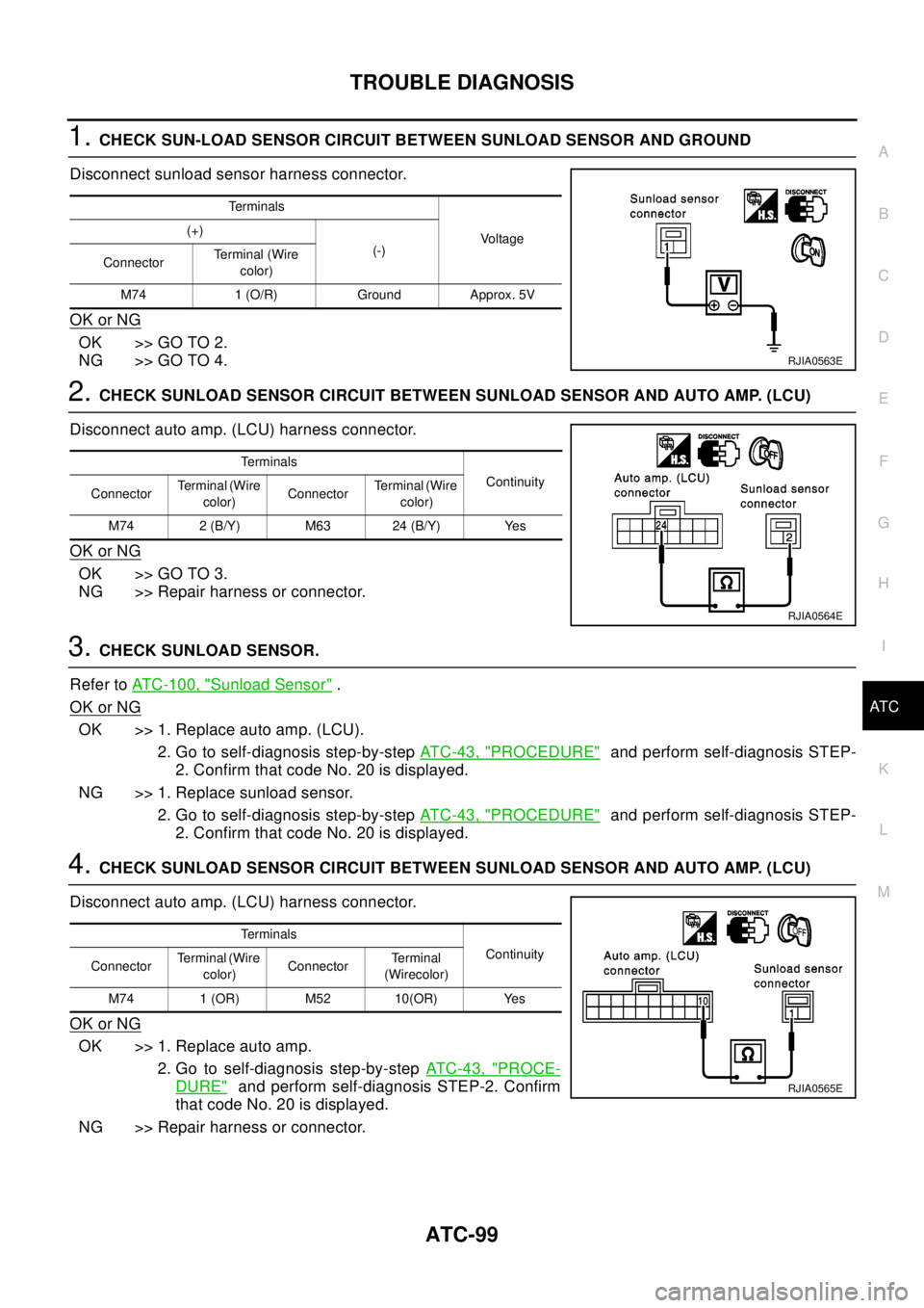
1.CHECK SUN-LOAD SENSOR CIRCUIT BETWEEN SUNLOAD SENSOR AND GROUND
Disconnect sunload sensor harness connector.
OK or NG
OK >> GO TO 2.
NG >> GO TO 4.
2.CHECK SUNLOAD SENSOR CIRCUIT BETWEEN SUNLOAD SENSOR AND AUTO AMP. (LCU)
Disconnect auto amp. (LCU) harness connector.
OK or NG
OK >> GO TO 3.
NG >> Repair harness or connector.
3.CHECK SUNLOAD SENSOR.
Refer toATC-100, "
Sunload Sensor".
OK or NG
OK >> 1. Replace auto amp. (LCU).
2. Go to self-diagnosis step-by-stepAT C - 4 3 , "
PROCEDURE"and perform self-diagnosis STEP-
2. Confirm that code No. 20 is displayed.
NG >> 1. Replace sunload sensor.
2. Go to self-diagnosis step-by-stepAT C - 4 3 , "
PROCEDURE"and perform self-diagnosis STEP-
2. Confirm that code No. 20 is displayed.
4.CHECK SUNLOAD SENSOR CIRCUIT BETWEEN SUNLOAD SENSOR AND AUTO AMP. (LCU)
Disconnect auto amp. (LCU) harness connector.
OK or NG
OK >> 1. Replace auto amp.
2. Go to self-diagnosis step-by-stepAT C - 4 3 , "
PROCE-
DURE"and perform self-diagnosis STEP-2. Confirm
that code No. 20 is displayed.
NG >> Repair harness or connector.
Te r m i n a l s
Vo l ta g e (+)
(-)
ConnectorTerminal (Wire
color)
M74 1 (O/R) Ground Approx. 5V
RJIA0563E
Te r m i n a l s
Continuity
ConnectorTerminal (Wire
color)ConnectorTerminal (Wire
color)
M74 2 (B/Y) M63 24 (B/Y) Yes
RJIA0564E
Te r m i n a l s
Continuity
ConnectorTerminal (Wire
color)ConnectorTe r m i n a l
(Wirecolor)
M74 1 (OR) M52 10(OR) Yes
RJIA0565E
Page 681 of 3066

TROUBLE DIAGNOSIS
ATC-103
C
D
E
F
G
H
I
K
L
MA
B
AT C
3.CHECK INTAKE SENSOR
Refer toATC-101, "
Intake Sensor"
OK or NG
OK >> 1. Replace auto amp.
2. Go to self-diagnosis step-by-stepAT C - 4 3 , "
PROCEDURE"and perform self-diagnosis STEP-
2.Confirm that code No. 20 is displayed.
NG >> 1. Replace intake sensor.
2. Go to self-diagnosis step-by-stepAT C - 4 3 , "
PROCEDURE"and perform self-diagnosis STEP-
2.Confirm that code No. 20 is displayed.
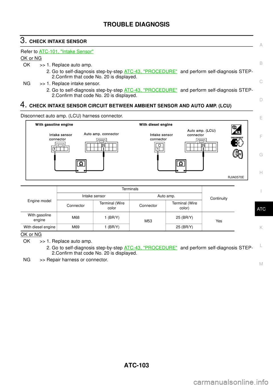
4.CHECK INTAKE SENSOR CIRCUIT BETWEEN AMBIENT SENSOR AND AUTO AMP. (LCU)
Disconnect auto amp. (LCU) harness connector.
OK or NG
OK >> 1. Replace auto amp.
2. Go to self-diagnosis step-by-stepAT C - 4 3 , "
PROCEDURE"and perform self-diagnosis STEP-
2.Confirm that code No. 20 is displayed.
NG >> Repair harness or connector.
Engine modelTerminals
Continuity Intake sensor Auto amp.
ConnectorTerminal (Wire
colorConnectorTerminal (Wire
color)
With gasoline
engineM68 1 (BR/Y)
M5325 (BR/Y)
Ye s
With diesel engine M69 1 (BR/Y) 25 (BR/Y)
RJIA0570E
Page 721 of 3066

REFRIGERANT LINES
ATC-143
C
D
E
F
G
H
I
K
L
MA
B
AT C
Check all around the service valves. Ensure service valve caps are secured on the service valves (to pre-
vent leaks).
NOTE:
After removing A/C manifold gauge set from service valves, wipe any residue from valves to prevent any
false readings by leak detector.
Cooling unit (Evaporator)
With engine OFF, turn blower fan on "High" for at least 15 seconds to dissipate any refrigerant trace in the
cooling unit. Wait a minimum of 10 minutes accumulation time (refer to the manufacturer's recommended
procedure for actual wait time) before inserting the leak detector probe into the drain hose.
Keep the probe inserted for at least 10 seconds. Use caution not to contaminate the probe tip with water
or dirt that may be in the drain hose.
5. If a leak detector detects a leak, verify at least once by blowing compressed air into area of suspected
leak, then repeat check as outlined above.
6. Do not stop when one leak is found. Continue to check for additional leaks at all system components.
If no leaks are found, perform steps 7 - 10.
7. Start engine.
8. Set the heater A/C control as follows;
a. A/C switch: ON
b. Face mode
c. Intake position: Recirculation
d. Max cold temperature
e. Fan speed: High
9. Run engine at 1,500 rpm for at least 2 minutes.
10. Turn engine off and perform leak check again following steps 4 through 6 above.
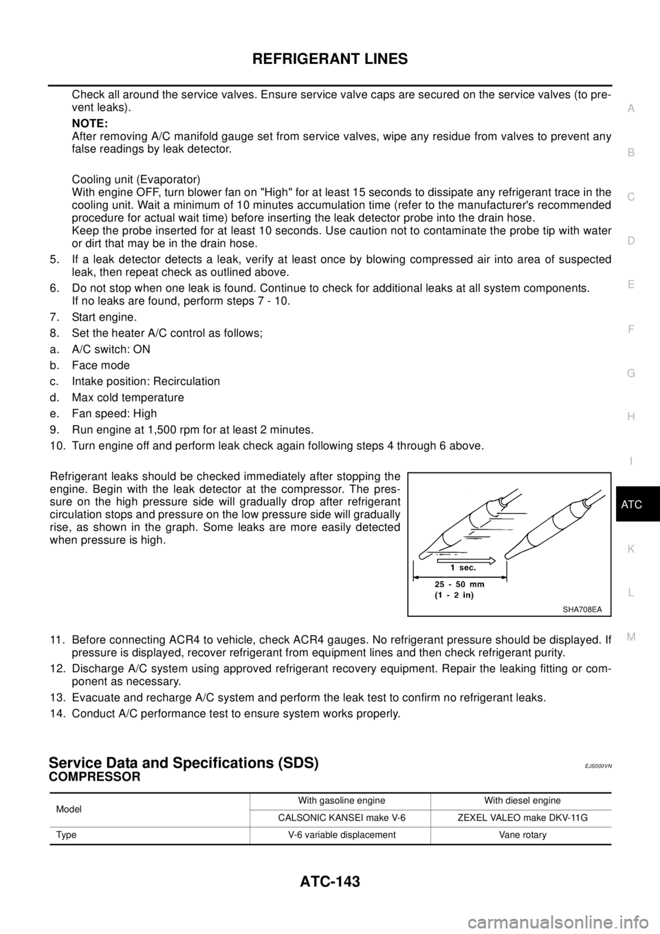
Refrigerant leaks should be checked immediately after stopping the
engine. Begin with the leak detector at the compressor. The pres-
sure on the high pressure side will gradually drop after refrigerant
circulation stops and pressure on the low pressure side will gradually
rise, as shown in the graph. Some leaks are more easily detected
when pressure is high.
11. Before connecting ACR4 to vehicle, check ACR4 gauges. No refrigerant pressure should be displayed. If
pressure is displayed, recover refrigerant from equipment lines and then check refrigerant purity.
12. Discharge A/C system using approved refrigerant recovery equipment. Repair the leaking fitting or com-
ponent as necessary.
13. Evacuate and recharge A/C system and perform the leak test to confirm no refrigerant leaks.
14. Conduct A/C performance test to ensure system works properly.
Service Data and Specifications (SDS)EJS000VN
COMPRESSOR
SHA708EA
ModelWith gasoline engine With diesel engine
CALSONIC KANSEI make V-6 ZEXEL VALEO make DKV-11G
Type V-6 variable displacement Vane rotary
Page 725 of 3066

AUDIO
AV-3
C
D
E
F
G
H
I
J
L
MA
B
AV
AUDIOP F P : 2 8 111
System DescriptionEKS002F2
Refer to Owner's Manual for audio system operating instructions.
Power is supplied at all times
lthrough 15A fuse (No. 32, located in the fusible link and fuse block)
lto audio unit terminal 3
lto CD auto changer terminal 32.
With the ignition switch in the ACC or ON position, power is supplied
lthrough 10A fuse [No. 4, located in the fuse block (J/B)]
lto audio unit terminal 6,
lto CD auto changer terminal 36
Ground is supplied through the case of the audio unit.
Audio signals are supplied
lthrough audio unit terminals 5, 7, 9, 10, 11, 13, 15, 16
lto terminals 1 and 2 of front door speaker LH and RH,
lto terminals 1 and 2 of rear door speaker LH and RH and
lto terminals 1 and 2 of tweeter LH and RH (with 6 speakers)
NATS AUDIO LINK
Description
The link with the NATS IMMU implies that the audio unit can basically only be operated if connected to the
matching NATS IMMU to which the audio unit was initially fitted on the production line.
Since radio operation is impossible after the link with the NATS is disrupted theft of the audio unit is basically
useless since special equipment is required to reset the audio unit.
Initialization process for audio units that are linked to the NATS IMMU
New audio units will be delivered to the factories in the “NEW” state, i.e. ready to be linked with the vehicle's
NATS. When the audio unit in “NEW” state is first switched on at the factory, it will start up communication with
the vehicle's immobilizer control unit (IMMU) and send a code (the “audio unit Code”) to the IMMU. The IMMU
will then store this code, which is unique to each audio unit, in its (permanent) memory.
Upon receipt of the code by the IMMU, the NATS will confirm correct receipt of the audio unit code to the audio
unit. Hereafter, the audio unit will operate as normal.
During the initialization process, “NEW” is displayed on the audio unit display. Normally though, communica-
tion between audio unit and IMMU takes such a short time (300 ms) that the audio unit seems to switch on
directly without showing “NEW” on its display.
Normal operation
Each time the audio unit is switched on afterwards, the audio unit code will be verified between the audio unit
and the NATS before the audio unit becomes operational. During the code verification process, “WAIT” is
shown on the audio unit display. Again, the communication takes such a short time (300 ms) that the audio
unit seems to switch on directly without showing “WAIT” on its display.
When the radio is locked
In case of a audio unit being linked with the vehicle's NATS (immobilizer system), disconnection of the link
between the audio unit and the IMMU will cause the audio unit to switch into the lock (“SECURE”) mode in
which the audio unit is fully inoperative. Hence, repair of the audio unit is basically impossible, unless the
audio unit is reset to the “NEW” state for which special decoding equipment is required.
Clarion has provided their authorized service representatives with so called “decoder boxes” which can bring
the audio unit back to the “NEW” state, enabling the audio unit to be switched on after which repair can be car-
ried out. Subsequently, when the repaired audio unit is delivered to the final user again, it will be in the “NEW”
state to enable re-linking the audio unit to the vehicle's immobilizer system. As a result of the above, repair of
the audio unit can only be done by an authorized Clarion representative (when the owner of the vehicle
requests repair and can show personal identification).
Page 726 of 3066

AV-4
AUDIO
Service Procedure
SPEED DEPENDENT VOLUME CONTROL
Description
If activated, the radio output volume will be automatically adjusted to compensate for increased driving noises
at higher driving speeds.
The radio receives a speed signal from the vehicle speed sensor (VSS) and selects the output volume.
PERSONAL AUDIO SETTINGS
Description
The radio is designed to store several settings (volume, bass, treble, preset stations and level of speed depen-
dent volume control) with every NATS ignition key used. Up to a maximum of 4 NATS keys can be registered.
During the communication mentioned under “Anti-Theft System”, the radio will recognize the used ignition key
and select the accompanying settings.
Item Service procedure Description
Battery disconnection No additional action required. —
Radio needs repair Repair needs to be done by authorized
representative of radio manufacturer since
radio cannot be operated unless it is reset
to NEW state, using special decoding
equipment.—
Replacement of radio by new part No additional action required. Radio is delivered in NEW state.
Transferring radio to another vehicle/
replacement of radio by an “old” partRadio needs to be reset to NEW state by
authorized representative of radio manu-
facturer.—
Replacement of IMMU Radio needs to be reset to NEW state by
authorized representative of Clarion.After switching on the radio, it will display
“SECURE” after 1 minute.
No communication from IMMU to radio 1. If NATS is malfunctioning, check NATS
system.
2. After NATS is repaired, reset radio to
NEW state by authorized representative
of Clarion.After switching on the radio, the radio will
display “SECURE” after 1 minute. Further
use of radio is impossible until communica-
tion is established again, or after radio is
reset by authorized representative of Clar-
ion.
When initialized between ECM and IMMU. Radio needs to be reset to NEW status by
authorized representative of Clarion.After switching on the radio, it will display
“SECURE” after 1 minute.
Page 734 of 3066

AV-12
AUDIO
Trouble Diagnoses
EKS002F5
AUDIO UNIT
InspectionEKS002F6
AUDIO UNIT
All voltage inspections are made with:
lIgnition switch ON or ACC
lAudio unit ON
lAudio unit connected (If audio unit is removed for inspection, supply a ground to the case using a jumper
wire.)
ANTENNA
Using a jumper wire, clip an auxiliary ground between antenna and body.
lIf reception improves, check antenna ground (at body surface).
lIf reception does not improve, check main feeder cable for short circuit or open circuit.
Symptom Possible causes Repair order
Audio unit inoperative (no digital display
and no sound from speakers).1. 10A fuse
2. Poor audio unit case ground
3. Audio unit1. Check 10A fuse [No. 4, located
in fuse block (J/B)]. Turn ignition
switch ON and verify that battery
positive voltage is present at ter-
minal 6 of audio unit.
2. Check audio unit case ground.
3. Remove audio unit for repair.
Audio unit presets are lost when ignition
switch is turned OFF.1. 15A fuse
2. Audio unit1. Check 15A fuse [No. 32, located
in fuse block (J/B)] and verify
that battery positive voltage is
present at terminal 3 of audio
unit.
2. Remove audio unit for repair.
Individual rear speaker is noisy or inopera-
tive.1. Each speaker
2. Output circuit to each speaker1. Check speaker.
2. Check the output circuits to each
speaker between audio unit and
each speaker.
AM/FM stations are weak or noisy. 1. Roof antenna
2. Audio unit ground
3. Audio unit1. Check roof antenna.
2. Check audio unit ground condi-
tion.
3. Remove audio unit for repair.
Audio unit generates noise in AM and FM
modes with engine running.1. Poor audio unit ground
2. Loose or missing ground bonding straps
3. Ignition condenser or rear window defogger
noise suppressor condenser
4. Ignition coil or secondary wiring
5. Audio unit1. Check audio unit ground.
2. Check ground bonding straps.
3. Replace ignition condenser or
rear window defogger noise sup-
pressor condenser.
4. Check ignition coil and second-
ary wiring.
5. Remove audio unit for repair.
Audio unit generates noise in AM and FM
modes with accessories on (switch pops
and motor noise).1. Poor audio unit ground
2. Antenna
3. Accessory ground
4. Malfunctioning accessory1. Check audio unit ground.
2. Check antenna.
3. Check accessory ground.
4. Replace accessory.
Page 735 of 3066

AUDIO
AV-13
C
D
E
F
G
H
I
J
L
MA
B
AV
RemovalandInstallationofAudioUnitEKS002PU
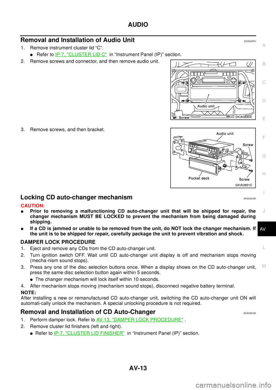
1. Remove instrument cluster lid “C”.
lRefer toIP-7, "CLUSTER LID C"in “Instrument Panel (IP)” section.
2. Remove screws and connector, and then remove audio unit.
3. Remove screws, and then bracket.
Locking CD auto-changer mechanismEKS002GM
CAUTION:
lPrior to removing a malfunctioning CD auto-changer unit that will be shipped for repair, the
changer mechanism MUST BE LOCKED to prevent the mechanism from being damaged during
shipping.
lIf a CD is jammed or unable to be removed from the unit, do NOT lock the changer mechanism. If
the unit is to be shipped for repair, carefully package the unit to prevent vibration and shock.
DAMPER LOCK PROCEDURE
1. Eject and remove any CDs from the CD auto-changer unit.
2. Turn ignition switch OFF. Wait until CD auto-changer unit display is off and mechanism stops moving
(mecha-nism sound stops).
3. Press any one of the disc selection buttons once. When a display shows on the CD auto-changer unit,
press the same disc selection button again within 5 seconds.
lThe changer mechanism will lock itself within 10 seconds.
4. After mechanism stops moving (mechanism sound stops), disconnect negative battery terminal.
NOTE:
After installing a new or remanufactured CD auto-changer unit, switching the CD auto-changer unit ON will
automati-cally unlock the mechanism. A special unlocking procedure is not required.
Removal and Installation of CD Auto-ChangerEKS002UW
1. Perform damper lock. Refer toAV- 1 3 , "DAMPER LOCK PROCEDURE".
2. Remove cluster lid finishers (left and right).
lRefer toIP-7, "CLUSTER LID FINISHER"in “Instrument Panel (IP)” section.
SKIA0890E
SKIA0891E
Page 822 of 3066

BL-78
NATS (NISSAN ANTI-THEFT SYSTEM)
Trouble Diagnoses
EIS001RX
SYMPTOM MATRIX CHART 1
Self-diagnosis related item
*: When NATS detects trouble, the security indicator lights up while ignition key is in the “ON” position.SYMPTOMDisplayed “SELF-DIAG
RESULTS ” on CON-
SULT-II screen.DIAGNOSTIC PROCE-
DURE
(Reference page)SYSTEM
(Malfunctioning part or
mode)REFERENCE PART NO.
OF ILLUSTRATION ON
SYSTEM DIAGRAM
lSecurity indicator
lighting up*
lEngine cannot be
startedECM INT CIRC-IMMUPROCEDURE 1
(BL-80
)ECM B
CHAIN OF ECM-IMMUPROCEDURE 2
(BL-80
)In rare case, “CHAIN OF
ECM-IMMU” might be
stored during key regis-
tration procedure, even if
the system is not mal-
functioning.—
Open circuit in battery
voltage line of IMMU cir-
cuitC1
Open circuit in ignition
line of IMMU circuitC2
Open circuit in ground
line of IMMU circuitC3
Open circuit in communi-
cation line between
IMMU and ECMC4
Short circuit between
IMMU and ECM commu-
nication line and battery
voltage lineC4
Short circuit between
IMMU and ECM commu-
nication line and ground
lineC4
ECM B
IMMU A
DIFFERENCE OF KEYPROCEDURE 3
(BL-82
)Unregistered key D
IMMU A
CHAIN OF IMMU-KEYPROCEDURE 4
(BL-83
)Malfunction of key ID
chipE
IMMU A
Open circuit in ground
line of dongle unit circuitC6
Open or short circuit in
line between IMMU and
dongle unitC5
Dongle unit G
ID DISCORD, IMM-ECMPROCEDURE 5
(BL-85
)System initialization has
not yet been completed.F
ECM B
LOCK MODEPROCEDURE 7
(BL-86
)LOCK MODE D
lMIL staying ON
lSecurity indicator
lighting up*DON'T ERASE
BEFORE CHECKING
ENG DIAGWORK FLOW
(BL-77)Engine trouble data and
NATS trouble data have
been detected in ECM—