Page 627 of 3066
TROUBLE DIAGNOSIS
ATC-49
C
D
E
F
G
H
I
K
L
MA
B
AT C
14.CHECK MALFUNCTIONING DOOR MOTOR POSITION SWITCH
Mode or (and) intake door motor position switch(es) is (are) malfunctioning.
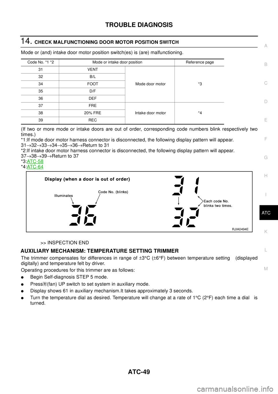
(If two or more mode or intake doors are out of order, corresponding code numbers blink respectively two
times.)
*1:If mode door motor harness connector is disconnected, the following display pattern will appear.
31®32®33®34®35®36®Return to 31
*2:If intake door motor harness connector is disconnected, the following display pattern will appear.
37®38®39®Return to 37
*3:AT C - 5 8
*4:AT C - 6 4
>> INSPECTION END
AUXILIARY MECHANISM: TEMPERATURE SETTING TRIMMER
The trimmer compensates for differences in range of±3°C(±6°F) between temperature setting (displayed
digitally) and temperature felt by driver.
Operating procedures for this trimmer are as follows:
lBegin Self-diagnosis STEP 5 mode.
lPress (fan) UP switch to set system in auxiliary mode.
lDisplay shows 61 in auxiliary mechanism.It takes approximately 3 seconds.
lTurn the temperature dial as desired. Temperature will change at a rate of 1°C(2°F)eachtimeadial is
turned.
Code No. *1 *2 Mode or intake door position Reference page
31 VENT
Mode door motor *3 32 B/L
34 FOOT
35 D/F
36 DEF
37 FRE
Intake door motor *4 38 20% FRE
39 REC
RJIA0494E
Page 628 of 3066
ATC-50
TROUBLE DIAGNOSIS
When battery cable is disconnected, trimmer operation is canceled. Temperature set becomes that of initial
condition, i.e. 0°C(0°F).
AUXILIARY MECHANISM: FOOT POSITION SETTING TRIMMER
Wind distribution ratio in Foot mode can be set.
Operating procedures for this trimmer are as follows:
lBegin Self-diagnosis STEP 5 mode.
lPress (fan) UP switch to set system in auxiliary mode.
lDisplay shows 61 in auxiliary mechanism.It takes approximately 3 seconds.
RJIA0495E
Page 629 of 3066
TROUBLE DIAGNOSIS
ATC-51
C
D
E
F
G
H
I
K
L
MA
B
AT C
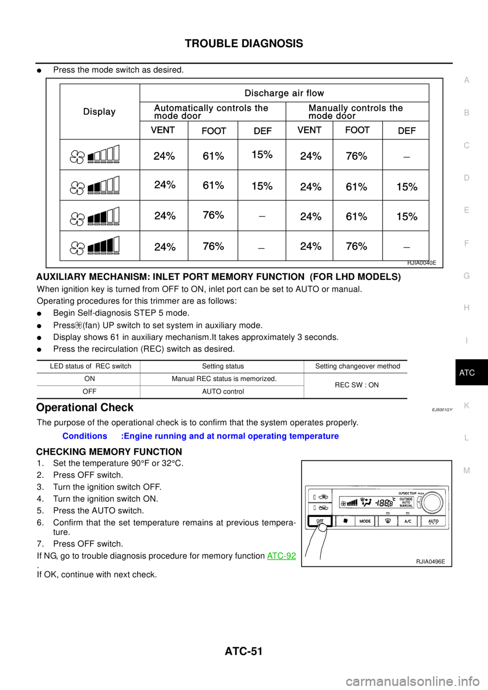
lPress the mode switch as desired.
AUXILIARY MECHANISM: INLET PORT MEMORY FUNCTION (FOR LHD MODELS)
When ignition key is turned from OFF to ON, inlet port can be set to AUTO or manual.
Operating procedures for this trimmer are as follows:
lBegin Self-diagnosis STEP 5 mode.
lPress (fan) UP switch to set system in auxiliary mode.
lDisplay shows 61 in auxiliary mechanism.It takes approximately 3 seconds.
lPress the recirculation (REC) switch as desired.
Operational CheckEJS001GY
The purpose of the operational check is to confirm that the system operates properly.
CHECKING MEMORY FUNCTION
1. Set the temperature 90°For32°C.
2. Press OFF switch.
3. Turn the ignition switch OFF.
4. Turn the ignition switch ON.
5. Press the AUTO switch.
6. Confirm that the set temperature remains at previous tempera-
ture.
7. Press OFF switch.
If NG, go to trouble diagnosis procedure for memory functionAT C - 9 2
.
If OK, continue with next check.
RJIA0040E
LED status of REC switch Setting status Setting changeover method
ON Manual REC status is memorized.
REC SW : ON
OFF AUTO control
Conditions :Engine running and at normal operating temperature
RJIA0496E
Page 631 of 3066
TROUBLE DIAGNOSIS
ATC-53
C
D
E
F
G
H
I
K
L
MA
B
AT C
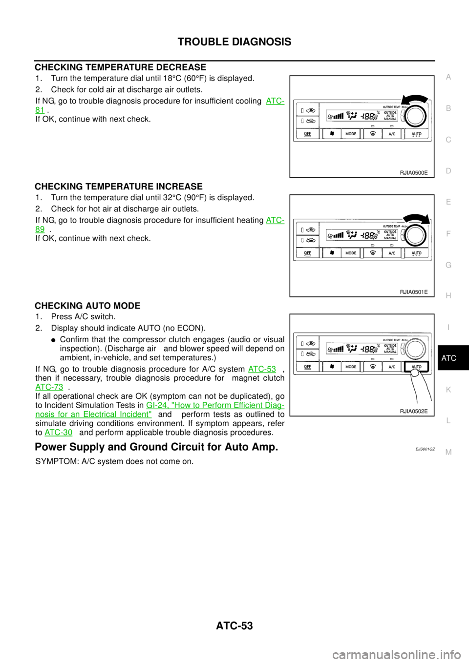
CHECKING TEMPERATURE DECREASE
1. Turn the temperature dial until 18°C(60°F) is displayed.
2. Check for cold air at discharge air outlets.
If NG, go to trouble diagnosis procedure for insufficient coolingAT C -
81.
If OK, continue with next check.
CHECKING TEMPERATURE INCREASE
1. Turn the temperature dial until 32°C(90°F) is displayed.
2. Check for hot air at discharge air outlets.
If NG, go to trouble diagnosis procedure for insufficient heatingAT C -
89.
If OK, continue with next check.
CHECKING AUTO MODE
1. Press A/C switch.
2. Display should indicate AUTO (no ECON).
lConfirm that the compressor clutch engages (audio or visual
inspection). (Discharge air and blower speed will depend on
ambient, in-vehicle, and set temperatures.)
If NG, go to trouble diagnosis procedure for A/C systemAT C - 5 3
,
then if necessary, trouble diagnosis procedure for magnet clutch
AT C - 7 3
.
If all operational check are OK (symptom can not be duplicated), go
to Incident Simulation Tests inGI-24, "
How to Perform Efficient Diag-
nosis for an Electrical Incident"and perform tests as outlined to
simulate driving conditions environment. If symptom appears, refer
toAT C - 3 0
and perform applicable trouble diagnosis procedures.
Power Supply and Ground Circuit for Auto Amp.EJS001GZ
SYMPTOM: A/C system does not come on.
RJIA0500E
RJIA0501E
RJIA0502E
Page 632 of 3066
ATC-54
TROUBLE DIAGNOSIS
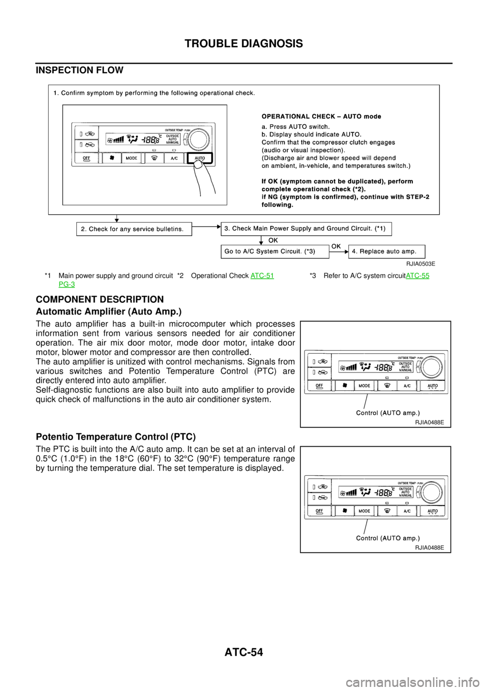
INSPECTION FLOW
COMPONENT DESCRIPTION
Automatic Amplifier (Auto Amp.)
The auto amplifier has a built-in microcomputer which processes
information sent from various sensors needed for air conditioner
operation. The air mix door motor, mode door motor, intake door
motor, blower motor and compressor are then controlled.
The auto amplifier is unitized with control mechanisms. Signals from
various switches and Potentio Temperature Control (PTC) are
directly entered into auto amplifier.
Self-diagnostic functions are also built into auto amplifier to provide
quick check of malfunctions in the auto air conditioner system.
Potentio Temperature Control (PTC)
The PTC is built into the A/C auto amp. It can be set at an interval of
0.5°C(1.0°F) in the 18°C(60°F) to 32°C(90°F) temperature range
by turning the temperature dial. The set temperature is displayed.
*1 Main power supply and ground circuit
PG-3*2 Operational CheckAT C - 5 1*3 Refer to A/C system circuitAT C - 5 5
RJIA0503E
RJIA0488E
RJIA0488E
Page 672 of 3066
ATC-94
TROUBLE DIAGNOSIS
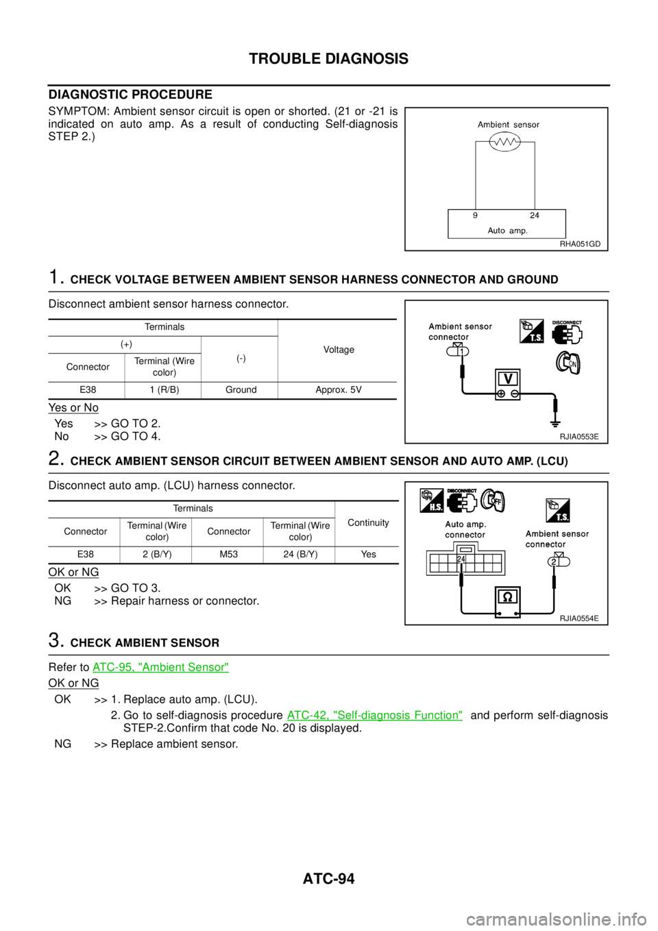
DIAGNOSTIC PROCEDURE
SYMPTOM: Ambient sensor circuit is open or shorted. (21 or -21 is
indicated on auto amp. As a result of conducting Self-diagnosis
STEP 2.)
1.CHECK VOLTAGE BETWEEN AMBIENT SENSOR HARNESS CONNECTOR AND GROUND
Disconnect ambient sensor harness connector.
Ye s o r N o
Yes >>GOTO2.
No >> GO TO 4.
2.CHECK AMBIENT SENSOR CIRCUIT BETWEEN AMBIENT SENSOR AND AUTO AMP. (LCU)
Disconnect auto amp. (LCU) harness connector.
OK or NG
OK >> GO TO 3.
NG >> Repair harness or connector.
3.CHECK AMBIENT SENSOR
Refer toATC-95, "
Ambient Sensor"
OK or NG
OK >> 1. Replace auto amp. (LCU).
2. Go to self-diagnosis procedureATC-42, "
Self-diagnosis Function"and perform self-diagnosis
STEP-2.Confirm that code No. 20 is displayed.
NG >> Replace ambient sensor.
RHA051GD
Te r m i n a l s
Voltag e (+)
(-)
ConnectorTerminal (Wire
color)
E38 1 (R/B) Ground Approx. 5V
RJIA0553E
Te r m i n a l s
Continuity
ConnectorTerminal (Wire
color)ConnectorTerminal (Wire
color)
E38 2 (B/Y) M53 24 (B/Y) Yes
RJIA0554E
Page 673 of 3066
TROUBLE DIAGNOSIS
ATC-95
C
D
E
F
G
H
I
K
L
MA
B
AT C
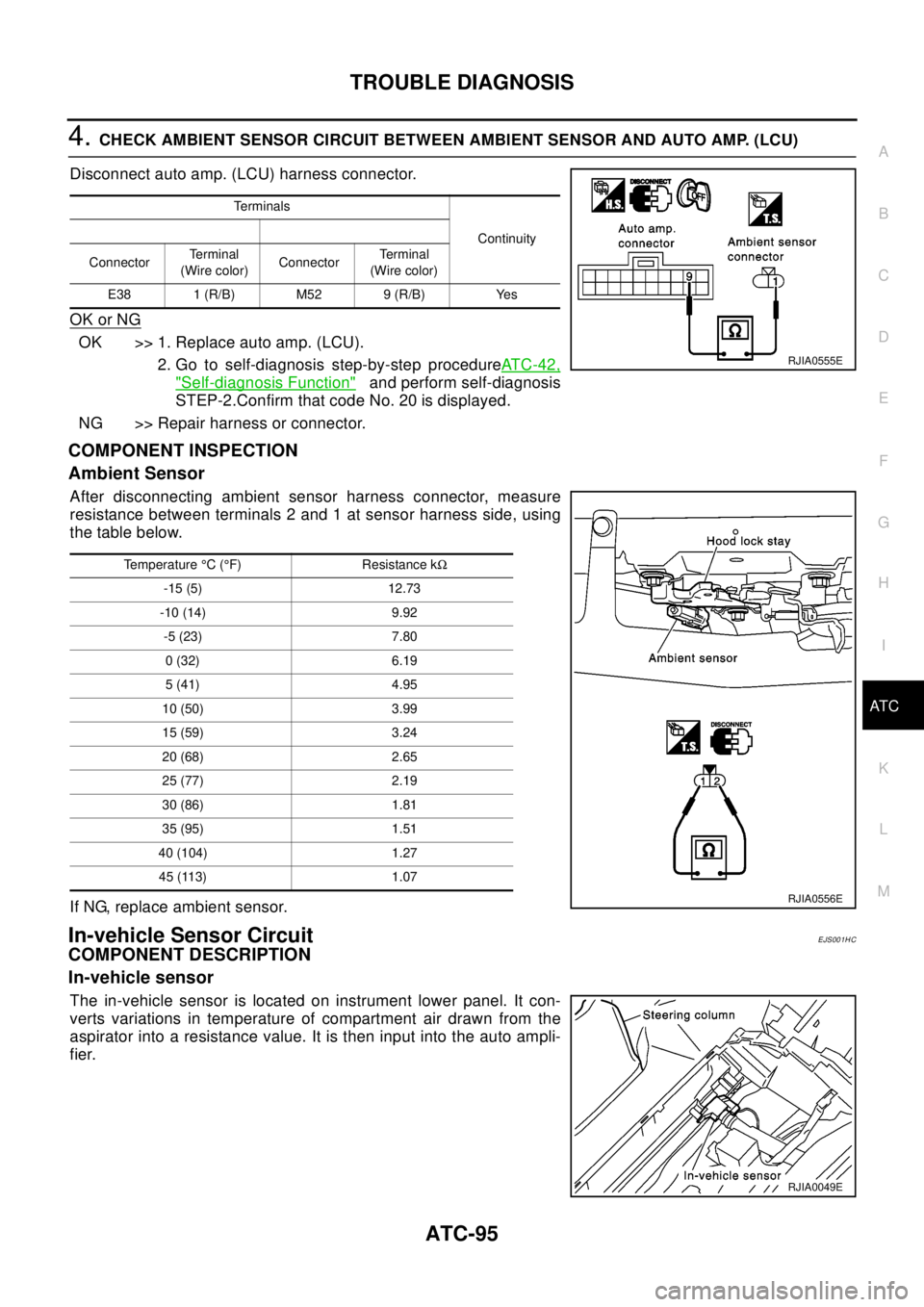
4.CHECK AMBIENT SENSOR CIRCUIT BETWEEN AMBIENT SENSOR AND AUTO AMP. (LCU)
Disconnect auto amp. (LCU) harness connector.
OK or NG
OK >> 1. Replace auto amp. (LCU).
2. Go to self-diagnosis step-by-step procedureAT C - 4 2 ,
"Self-diagnosis Function"and perform self-diagnosis
STEP-2.Confirm that code No. 20 is displayed.
NG >> Repair harness or connector.
COMPONENT INSPECTION
Ambient Sensor
After disconnecting ambient sensor harness connector, measure
resistance between terminals 2 and 1 at sensor harness side, using
the table below.
If NG, replace ambient sensor.
In-vehicle Sensor CircuitEJS001HC
COMPONENT DESCRIPTION
In-vehicle sensor
The in-vehicle sensor is located on instrument lower panel. It con-
verts variations in temperature of compartment air drawn from the
aspirator into a resistance value. It is then input into the auto ampli-
fier.
Te r m i n a l s
Continuity
ConnectorTe r m i n a l
(Wire color)ConnectorTerminal
(Wire color)
E38 1 (R/B) M52 9 (R/B) Yes
RJIA0555E
Temperature°C(°F) Resistance kW
-15 (5) 12.73
-10 (14) 9.92
-5 (23) 7.80
0(32) 6.19
5(41) 4.95
10 (50) 3.99
15 (59) 3.24
20 (68) 2.65
25 (77) 2.19
30 (86) 1.81
35 (95) 1.51
40 (104) 1.27
45 (113) 1.07
RJIA0556E
RJIA0049E
Page 675 of 3066
TROUBLE DIAGNOSIS
ATC-97
C
D
E
F
G
H
I
K
L
MA
B
AT C
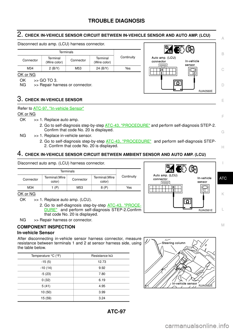
2.CHECK IN-VEHICLE SENSOR CIRCUIT BETWEEN IN-VEHICLE SENSOR AND AUTO AMP. (LCU)
Disconnect auto amp. (LCU) harness connector.
OK or NG
OK >> GO TO 3.
NG >> Repair harness or connector.
3.CHECK IN-VEHICLE SENSOR
Refer toAT C - 9 7 , "
In-vehicle Sensor"
OK or NG
OK >> 1. Replace auto amp.
2. Go to self-diagnosis step-by-stepAT C - 4 3 , "
PROCEDURE"and perform self-diagnosis STEP-2.
Confirm that code No. 20 is displayed.
NG >> 1. Replace in-vehicle sensor.
2. Go to self-diagnosis step-by-stepAT C - 4 3 , "
PROCEDURE"and perform self-diagnosis STEP-
2. Confirm that code No. 20 is displayed.
4.CHECK IN-VEHICLE SENSOR CIRCUIT BETWEEN AMBIENT SENSOR AND AUTO AMP. (LCU)
Disconnect auto amp. (LCU) harness connector.
OK or NG
OK >> 1. Replace auto amp. (LCU).
2. Go to self-diagnosis step-by-stepAT C - 4 3 , "
PROCE-
DURE"and perform self-diagnosis STEP-2.Confirm
that code No. 20 is displayed.
NG >> Repair harness or connector.
COMPONENT INSPECTION
In-vehicle Sensor
After disconnecting in-vehicle sensor harness connector, measure
resistance between terminals 1 and 2 at sensor harness side, using
the table below.
Te r m i n a l s
Continuity
ConnectorTe r m i n a l
(Wire color)ConnectorTe r m i n a l
(Wire color)
M34 2 (B/Y) M53 24 (B/Y) Yes
RJIA0560E
Te r m i n a l s
Continuity
ConnectorTerminal (Wire
color)ConnectorTerminal (Wire
color)
M34 1 (P) M53 8 (P) Yes
RJIA0561E
Temperature°C(°F) Resistance kW
-15 (5) 12.73
-10 (14) 9.92
-5 (23) 7.80
0(32) 6.19
5(41) 4.95
10 (50) 3.99
15 (59) 3.24
RJIA0562E