2003 NISSAN X-TRAIL sensor
[x] Cancel search: sensorPage 719 of 3066

REFRIGERANT LINES
ATC-141
C
D
E
F
G
H
I
K
L
MA
B
AT C
CAUTION:
Moving the electronic leak detector probe slower and closer to the suspected leak area will improve
the chances of finding a leak.
Checking System for Leaks Using the Fluorescent Leak DetectorEJS000VK
1. Check A/C system for leaks using the UV lamp and safety glasses (J-42220) in a low sunlight area (area
without windows preferable). Illuminate all components, fittings and lines. The dye will appear as a bright
green/yellow area at the point of leakage. Fluorescent dye observed at the evaporator drain opening indi-
cates an evaporator core assembly (tubes, core or TXV) leak.
2. If the suspected area is difficult to see, use an adjustable mirror or wipe the area with a clean shop rag or
cloth, with the UV lamp for dye residue.
3. After the leak is repaired, remove any residual dye using dye cleaner (J-43872) to prevent future misdiag-
nosis.
4. Perform a system performance check and verify the leak repair with an approved electronic refrigerant
leak detector.
NOTE:
Other gases in the work area or substances on the A/C components, for example, anti-freeze, windshield
washer fluid, solvents and lubricants, may falsely trigger the leak detector. Make sure the surfaces to be
checked are clean.
Clean with a dry cloth or blow off with shop air.
Do not allow the sensor tip of the detector to contact with any substance. This can also cause false readings
and may damage the detector.
Dye InjectionEJS000VL
(This procedure is only necessary when recharging the system or when the compressor has seized and was
replaced.)
1. Check A/C system static (at rest) pressure. Pressure must be at least 345 kPa (50 psi).
2. Pour one bottle (1/4 ounce / 7.4 cc) of the A/C refrigerant dye into the injector tool (J-41459).
3. Connect the injector tool to the A/C LOW PRESSURE side service fitting.
4. Start engine and switch A/C ON.
5. When the A/C operating (compressor running), inject one bottle (1/4 ounce / 7.4 cc) of fluorescent dye
through the low-pressure service valve using dye injector tool J-41459 (refer to the manufacture's operat-
ing instructions).
6. With the engine still running, disconnect the injector tool from the service fitting.
CAUTION:
Be careful the A/C system or replacing a component, pour the dye directly into the open system con-
nection and proceed with the service procedures.
7. Operate the A/C system for a minimum of 20 minutes to mix the dye with the system oil. Depending on the
leak size, operating conditions and location of the leak, it may take from minutes to days for the dye to
penetrate a leak and become visible.
Electronic Refrigerant Leak DetectorEJS000VM
PRECAUTIONS FOR HANDLING LEAK DETECTOR
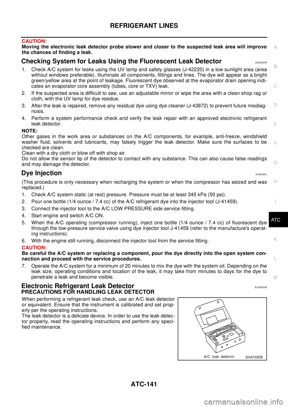
When performing a refrigerant leak check, use an A/C leak detector
or equivalent. Ensure that the instrument is calibrated and set prop-
erly per the operating instructions.
The leak detector is a delicate device. In order to use the leak detec-
tor properly, read the operating instructions and perform any speci-
fied maintenance.
SHA705EB
Page 720 of 3066

ATC-142
REFRIGERANT LINES
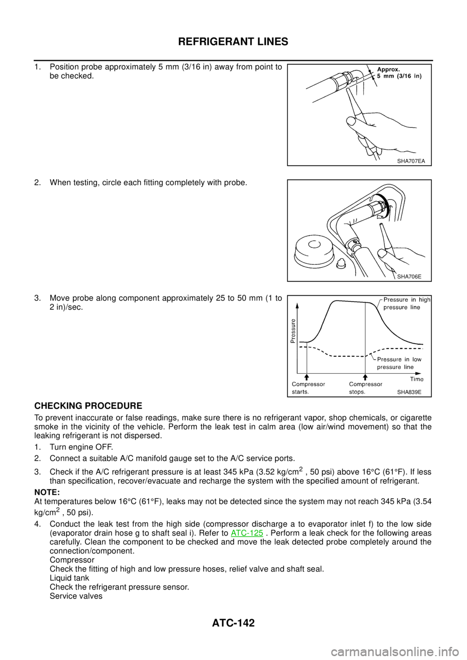
1. Position probe approximately 5 mm (3/16 in) away from point to
be checked.
2. When testing, circle each fitting completely with probe.
3. Move probe along component approximately 25 to 50 mm (1 to
2 in)/sec.
CHECKING PROCEDURE
To prevent inaccurate or false readings, make sure there is no refrigerant vapor, shop chemicals, or cigarette
smoke in the vicinity of the vehicle. Perform the leak test in calm area (low air/wind movement) so that the
leaking refrigerant is not dispersed.
1. Turn engine OFF.
2. Connect a suitable A/C manifold gauge set to the A/C service ports.
3. Check if the A/C refrigerant pressure is at least 345 kPa (3.52 kg/cm
2,50psi)above16°C(61°F).Ifless
than specification, recover/evacuate and recharge the system with the specified amount of refrigerant.
NOTE:
At temperatures below 16°C(61°F), leaks may not be detected since the system may not reach 345 kPa (3.54
kg/cm
2,50psi).
4. Conduct the leak test from the high side (compressor discharge a to evaporator inlet f) to the low side
(evaporator drain hose g to shaft seal i). Refer toATC-125
. Perform a leak check for the following areas
carefully. Clean the component to be checked and move the leak detected probe completely around the
connection/component.
Compressor
Check the fitting of high and low pressure hoses, relief valve and shaft seal.
Liquid tank
Check the refrigerant pressure sensor.
Service valves
SHA707EA
SHA706E
SHA839E
Page 726 of 3066

AV-4
AUDIO
Service Procedure
SPEED DEPENDENT VOLUME CONTROL
Description
If activated, the radio output volume will be automatically adjusted to compensate for increased driving noises
at higher driving speeds.
The radio receives a speed signal from the vehicle speed sensor (VSS) and selects the output volume.
PERSONAL AUDIO SETTINGS
Description
The radio is designed to store several settings (volume, bass, treble, preset stations and level of speed depen-
dent volume control) with every NATS ignition key used. Up to a maximum of 4 NATS keys can be registered.
During the communication mentioned under “Anti-Theft System”, the radio will recognize the used ignition key
and select the accompanying settings.
Item Service procedure Description
Battery disconnection No additional action required. —
Radio needs repair Repair needs to be done by authorized
representative of radio manufacturer since
radio cannot be operated unless it is reset
to NEW state, using special decoding
equipment.—
Replacement of radio by new part No additional action required. Radio is delivered in NEW state.
Transferring radio to another vehicle/
replacement of radio by an “old” partRadio needs to be reset to NEW state by
authorized representative of radio manu-
facturer.—
Replacement of IMMU Radio needs to be reset to NEW state by
authorized representative of Clarion.After switching on the radio, it will display
“SECURE” after 1 minute.
No communication from IMMU to radio 1. If NATS is malfunctioning, check NATS
system.
2. After NATS is repaired, reset radio to
NEW state by authorized representative
of Clarion.After switching on the radio, the radio will
display “SECURE” after 1 minute. Further
use of radio is impossible until communica-
tion is established again, or after radio is
reset by authorized representative of Clar-
ion.
When initialized between ECM and IMMU. Radio needs to be reset to NEW status by
authorized representative of Clarion.After switching on the radio, it will display
“SECURE” after 1 minute.
Page 741 of 3066

TIME CONTROL UNIT
BCS-3
C
D
E
F
G
H
I
J
L
MA
B
BCS
TIME CONTROL UNITPFP:28491
DescriptionEKS002ZU
OUTLINE
The time control unit totally controls the following body electrical system operations.
lWarning chime
lRear defogger
lPower door lock
lInterior lamp
INPUT/OUTPUT
System Input Output
PowerdoorlockDoor lock and unlock switch
Door switches
Door unlock sensor
Door key cylinder switch (driver side)Door lock actuators
Warning chimeKey switch (Insert)
Ignition switch (ON)
Lighting switch (1st)
Front door switch (driver side)
Door unlock sensorWarning chime (located in time control unit)
Rear window defoggerIgnition switch (ON)
Rear window defogger switchRear window defogger relay
Interior lampDoor switches
Front door unlock sensor
Ignition switch (ON)
Key switch (Insert)Interior lamp
Page 743 of 3066

TIME CONTROL UNIT
BCS-5
C
D
E
F
G
H
I
J
L
MA
B
BCS
Time Control Unit Inspection TableEKS002ZW
Te r m i n a l
No.Wire
colorConnections Operation conditionVo l ta g e
(Approxi-
mate values)
1 L/B Power source (Fuse) — 12V
3 L/Y Super lock actuator Door key cylinder switchFree 0V
Unlocked 12V
4G/RPassenger and rear doors lock
actuatorDoor lock/unlock switchFree 0V
Unlocked 12V
6 Y/R Super lock actuator Door key cylinder switchFree 0V
Locked 12V
10 W Power source (C/B) — 12V
11 L Driver's door lock actuator Door lock/unlock switchFree 0V
Unlocked 12V
14 R/B Door lock actuator Door lock/unlock switchFree 0V
Locked 12V
16 B Ground — 0V
17 G Ignition switch (ON) — 12V
18 W/L Ignition key switch (Insert) Key inserted®key removed from IGN key cylinder 12V®0V
19 R/L Lighting switch 1ST, 2ND position: ON®OFF 12V®0V
20 GY Door lock/Unlock switch Neutral®Locks 5V®0V
23 PU Door lock/Unlock switch Neutral®Unlocks 5V®0V
24 OR/L Door key cylinder switch OFF (Neutral)®ON (Locked) 5V®0V
25 W/L Door key cylinder switch OFF (Neutral)®ON (Unlocked) 5V®0V
26 R/Y Interior room lampWhen interior room lamp is operated using remote control-
ler (Lamp switch is “DOOR” position)12V®0V
27 G/W Rear window defogger relay OFF®ON (Ignition key is in “ON” position) 12V®0V
28 Y/G Driver door unlock sensor Driver door: Locked®Unlocked 5V®0V
29 Y/L Passenger door unlock sensor Passenger door: Locked®Unlocked 5V®0V
30 R Doorswitchdriverside OFF(closed)®ON (open) 5V®0V
31 R/W Passenger and rear doors switch OFF (closed)®ON (open) 5V®0V
32 OR Multi-remote control unitRemote controller lock button is pushed.
(Ignition switch is not at “ON” position)0V®5V
33 P/L Multi-remote control unitRemote controller unlock button is pushed.
(Ignition switch is not at “ON” position)0V®5V
35 LG/B Rear window defogger switch OFF®ON 5V®0V
Page 745 of 3066

BL-1
BODY, LOCK & SECURITY SYSTEM
IBODY
CONTENTS
C
D
E
F
G
H
J
K
L
M
SECTION
A
B
BL
BODY, LOCK & SECURITY SYSTEM
PRECAUTIONS .......................................................... 3
Precautions .............................................................. 3
HOOD ......................................................................... 4
Fitting Adjustment .................................................... 4
FRONT END HEIGHT ADJUSTMENT AND LAT-
ERAL/LONGITUDIAL CLEARANCE ADJUST-
MENT .................................................................... 4
SURFACE HEIGHT ADJUSTMENT ..................... 4
Removal and Installation of Hood Assembly ............ 5
Removal and Installation of Hood Lock Control ....... 6
REMOVAL ............................................................. 6
INSTALLATION ..................................................... 7
Hood Lock Control Inspection .................................. 7
DOOR ......................................................................... 8
Fitting Adjustment .................................................... 8
FRONT DOOR ...................................................... 8
REAR DOOR ........................................................ 8
STRIKER ADJUSTMENT ..................................... 9
Removal and Installation .......................................... 9
Door Weatherstrip .................................................. 10
POWER DOOR LOCK SYSTEM ...............................11
System Description .................................................11
OPERATION ........................................................11
Component Parts and Harness Connector Location....11
Schematic .............................................................. 12
Wiring Diagram — D/LOCK — ............................... 13
Terminal and Reference Value for Time Control Unit... 17
Symptom Chart ...................................................... 17
Power Supply and Ground Circuit Check ............... 18
Door Lock/Unlock Switch Check ............................ 18
Door Key Cylinder Switch Check ........................... 19
Door Lock Actuator Check ..................................... 20
Door Switch Check ................................................. 21
Door Unlock Sensor Check .................................... 22
Key Switch Check .................................................. 23
POWER DOOR LOCK — SUPER LOCK — ............ 24
System Description ................................................ 24
OUTLINE ............................................................. 24
OPERATION ....................................................... 24
Schematic .............................................................. 26Wiring Diagram — S/LOCK — ............................... 27
Terminal and Reference Value for Time Control Unit... 33
Trouble Diagnoses ................................................. 34
PRELIMINARY CHECK ....................................... 34
SYMPTOM CHART ............................................. 35
Power Supply and Ground Circuit Check ............... 36
Door Lock/Unlock Switch Check ............................ 36
Door Key Cylinder Switch Check ............................ 37
Door Lock Actuator Check ...................................... 38
Door Switch Check ................................................. 39
Door Unlock Sensor Check .................................... 40
Key Switch Check ................................................... 41
Super Lock Actuator Check .................................... 42
NATS Release Signal Check .................................. 43
Ignition Switch “ON” Circuit Check ......................... 44
Remote Controller Signal Check ............................ 44
MULTI-REMOTE CONTROL SYSTEM ..................... 45
Component Parts and Harness Connector Location... 45
System Description ................................................. 45
FUNCTION .......................................................... 45
LOCK OPERATION ............................................. 45
UNLOCK OPERATION ........................................ 46
HAZARD REMINDER ......................................... 46
MULTI-REMOTE CONTROLLER ID CODE
ENTRY ................................................................ 46
Wiring Diagram — MULTI — .................................. 47
Terminal and Reference Value for Multi-remote
Control Unit ............................................................. 49
Symptom Chart ....................................................... 49
Remote Controller Battery Check ........................... 49
Power Supply and Ground Circuit Check ............... 50
Hazard Reminder Check ........................................ 51
ID Code Entry Procedure ....................................... 52
Remote Controller Battery Replacement ................ 53
FRONT DOOR LOCK ............................................... 54
Component Parts Location ..................................... 54
Inspection and Adjustment ..................................... 54
OUT SIDE HANDLE ROD ADJUSTMENT .......... 54
Removal and Installation ........................................ 54
REMOVAL ........................................................... 54
Page 755 of 3066

POWERDOORLOCKSYSTEM
BL-11
C
D
E
F
G
H
J
K
L
MA
B
BL
POWER DOOR LOCK SYSTEMPFP:24814
System DescriptionEIS001SE
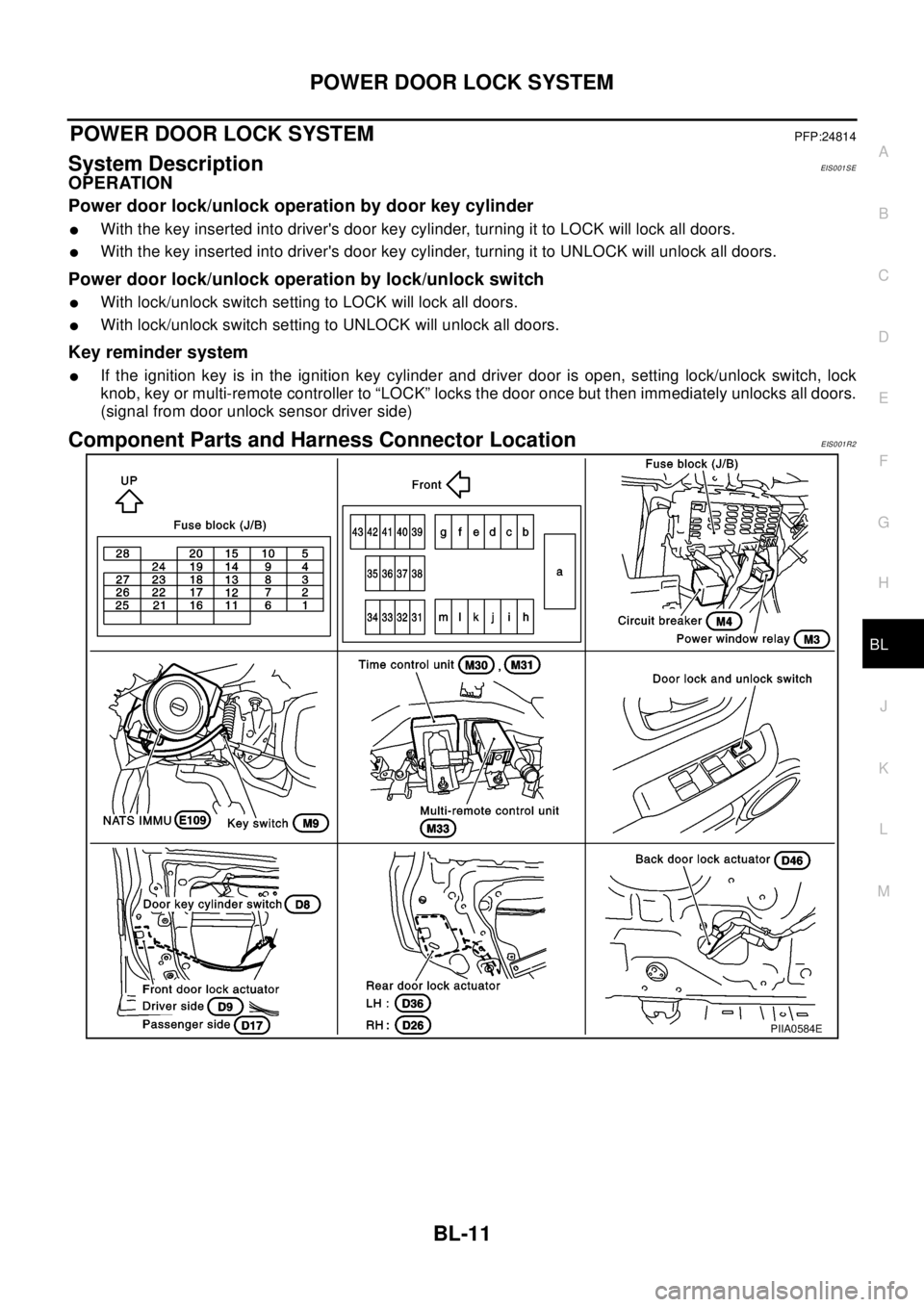
OPERATION
Power door lock/unlock operation by door key cylinder
lWith the key inserted into driver's door key cylinder, turning it to LOCK will lock all doors.
lWith the key inserted into driver's door key cylinder, turning it to UNLOCK will unlock all doors.
Power door lock/unlock operation by lock/unlock switch
lWith lock/unlock switch setting to LOCK will lock all doors.
lWith lock/unlock switch setting to UNLOCK will unlock all doors.
Key reminder system
lIf the ignition key is in the ignition key cylinder and driver door is open, setting lock/unlock switch, lock
knob, key or multi-remote controller to “LOCK” locks the door once but then immediately unlocks all doors.
(signal from door unlock sensor driver side)
Component Parts and Harness Connector LocationEIS001R2
PIIA0584E
Page 761 of 3066

POWERDOORLOCKSYSTEM
BL-17
C
D
E
F
G
H
J
K
L
MA
B
BL
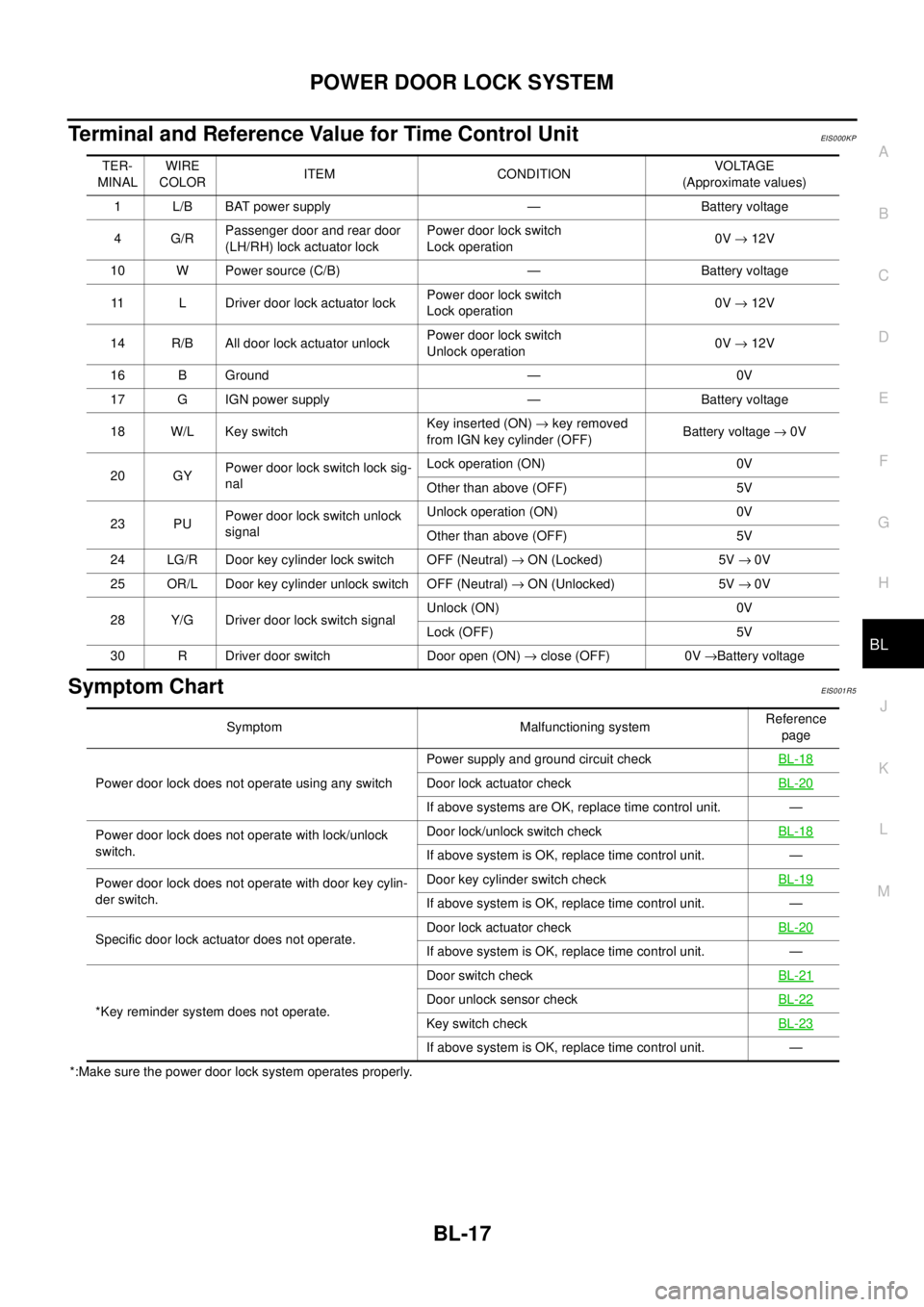
Terminal and Reference Value for Time Control UnitEIS000KP
Symptom ChartEIS001R5
*:Make sure the power door lock system operates properly.TER-
MINALWIRE
COLORITEM CONDITIONVOLTAGE
(Approximate values)
1 L/B BAT power supply — Battery voltage
4G/RPassenger door and rear door
(LH/RH) lock actuator lockPower door lock switch
Lock operation0V®12V
10 W Power source (C/B) — Battery voltage
11 L Driver door lock actuator lockPower door lock switch
Lock operation0V®12V
14 R/B All door lock actuator unlockPower door lock switch
Unlock operation0V®12V
16 B Ground — 0V
17 G IGN power supply — Battery voltage
18 W/L Key switchKey inserted (ON)®key removed
from IGN key cylinder (OFF)Battery voltage®0V
20 GYPower door lock switch lock sig-
nalLock operation (ON) 0V
Other than above (OFF) 5V
23 PUPower door lock switch unlock
signalUnlock operation (ON) 0V
Other than above (OFF) 5V
24 LG/R Door key cylinder lock switch OFF (Neutral)®ON (Locked) 5V®0V
25 OR/L Door key cylinder unlock switch OFF (Neutral)®ON (Unlocked) 5V®0V
28 Y/G Driver door lock switch signalUnlock (ON) 0V
Lock (OFF) 5V
30 R Driver door switch Door open (ON)®close (OFF) 0V®Battery voltage
Symptom Malfunctioning systemReference
page
Power door lock does not operate using any switchPower supply and ground circuit checkBL-18
Door lock actuator checkBL-20
If above systems are OK, replace time control unit. —
Power door lock does not operate with lock/unlock
switch.Door lock/unlock switch checkBL-18
If above system is OK, replace time control unit. —
Power door lock does not operate with door key cylin-
der switch.Door key cylinder switch checkBL-19
If above system is OK, replace time control unit. —
Specific door lock actuator does not operate.Door lock actuator checkBL-20
If above system is OK, replace time control unit. —
*Key reminder system does not operate.Door switch checkBL-21
Door unlock sensor checkBL-22
Key switch checkBL-23
If above system is OK, replace time control unit. —