Page 683 of 3066
AMBIENT SENSOR
ATC-105
C
D
E
F
G
H
I
K
L
MA
B
AT C
AMBIENT SENSORPFP:27722
Removal and InstallationEJS000UH
1. Remove the front grille.
2. Remove the ambient sensor.
RJIA0048E
Page 684 of 3066
ATC-106
IN-VEHICLE SENSOR
IN-VEHICLE SENSOR
PFP:27720
Removal and InstallationEJS000UI
1. Remove the cluster lid A.
2. Remove the in-vehicle sensor.
RJIA0049E
Page 685 of 3066
SUNLOAD SENSOR
ATC-107
C
D
E
F
G
H
I
K
L
MA
B
AT C
SUNLOAD SENSORPFP:27721
Removal and InstallationEJS000UJ
1. Remove the sunload sensor garnish.
2. Remove the sunoad sensor.
RJIA0050E
Page 686 of 3066
ATC-108
INTAKE SENSOR CIRCUIT
INTAKE SENSOR CIRCUIT
PFP:27723
Removal and InstallationEJS000UK
1. Remove the evaporator. Refer toATC-139, "Removal and Instal-
lation for Evaporator"
2. Remove the intake sensor.
RJIA0051E
Page 695 of 3066
HEATER & COOLING UNIT ASSEMBLY
ATC-117
C
D
E
F
G
H
I
K
L
MA
B
AT C
16 Screw 17 Ventilator door link 1 18 Ventilator door link 2
19 Ventilator door lever 20 Rod 21 Rod holder
22 Main link 23 Max cool door lever 24 Defroster door lever
25 Screw 26 Foot duct (right side) 27 Heater core
28 Heater core cover 29 Foot duct (left side) 30 Intake sensor bracket
31 Intake sensor 32 Screw 33 Aspirator
34 Screw 35 Heater & cooling unit case (right side) 36 Defroster door
37 Ventilator door 38 Max cool door 39 Heater & cooling unit case (left side)
Page 715 of 3066

REFRIGERANT LINES
ATC-137
C
D
E
F
G
H
I
K
L
MA
B
AT C
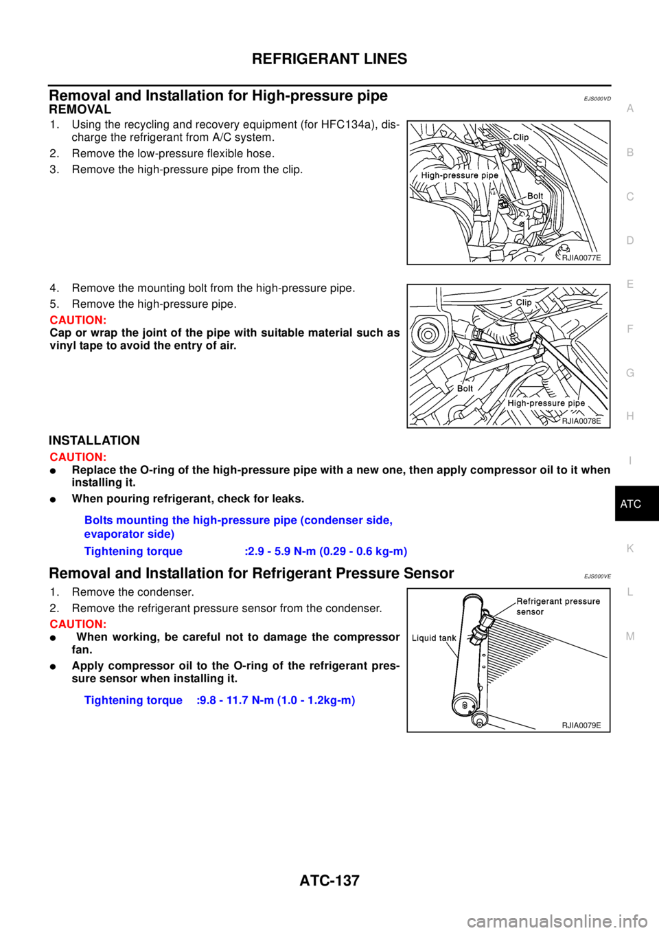
Removal and Installation for High-pressure pipeEJS000VD
REMOVAL
1. Using the recycling and recovery equipment (for HFC134a), dis-
charge the refrigerant from A/C system.
2. Remove the low-pressure flexible hose.
3. Remove the high-pressure pipe from the clip.
4. Remove the mounting bolt from the high-pressure pipe.
5. Remove the high-pressure pipe.
CAUTION:
Cap or wrap the joint of the pipe with suitable material such as
vinyl tape to avoid the entry of air.
INSTALLATION
CAUTION:
lReplace the O-ring of the high-pressure pipe with a new one, then apply compressor oil to it when
installing it.
lWhen pouring refrigerant, check for leaks.
Removal and Installation for Refrigerant Pressure SensorEJS000VE
1. Remove the condenser.
2. Remove the refrigerant pressure sensor from the condenser.
CAUTION:
lWhen working, be careful not to damage the compressor
fan.
lApply compressor oil to the O-ring of the refrigerant pres-
sure sensor when installing it.
RJIA0077E
RJIA0078E
Bolts mounting the high-pressure pipe (condenser side,
evaporator side)
Tighteningtorque :2.9-5.9N-m(0.29-0.6kg-m)
Tightening torque :9.8 - 11.7 N-m (1.0 - 1.2kg-m)
RJIA0079E
Page 716 of 3066

ATC-138
REFRIGERANT LINES
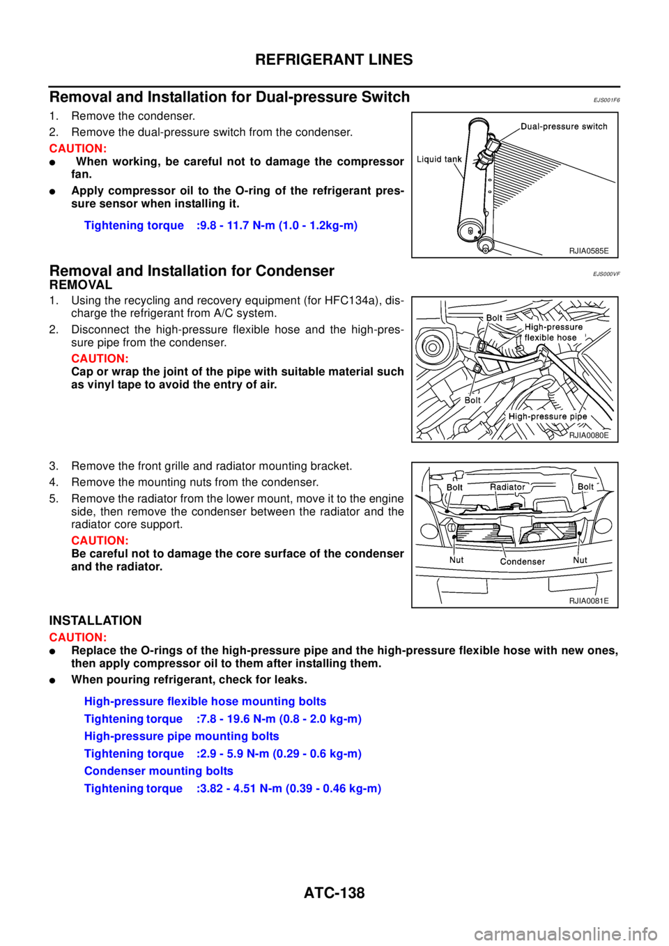
Removal and Installation for Dual-pressure Switch
EJS001F6
1. Remove the condenser.
2. Remove the dual-pressure switch from the condenser.
CAUTION:
lWhen working, be careful not to damage the compressor
fan.
lApply compressor oil to the O-ring of the refrigerant pres-
sure sensor when installing it.
Removal and Installation for CondenserEJS000VF
REMOVAL
1. Using the recycling and recovery equipment (for HFC134a), dis-
charge the refrigerant from A/C system.
2. Disconnect the high-pressure flexible hose and the high-pres-
sure pipe from the condenser.
CAUTION:
Cap or wrap the joint of the pipe with suitable material such
as vinyl tape to avoid the entry of air.
3. Remove the front grille and radiator mounting bracket.
4. Remove the mounting nuts from the condenser.
5. Remove the radiator from the lower mount, move it to the engine
side, then remove the condenser between the radiator and the
radiator core support.
CAUTION:
Be careful not to damage the core surface of the condenser
and the radiator.
INSTALLATION
CAUTION:
lReplace the O-rings of the high-pressure pipe and the high-pressure flexible hose with new ones,
then apply compressor oil to them after installing them.
lWhen pouring refrigerant, check for leaks.Tightening torque :9.8 - 11.7 N-m (1.0 - 1.2kg-m)
RJIA0585E
RJIA0080E
RJIA0081E
High-pressure flexible hose mounting bolts
Tightening torque :7.8 - 19.6 N-m (0.8 - 2.0 kg-m)
High-pressure pipe mounting bolts
Tightening torque :2.9 - 5.9 N-m (0.29 - 0.6 kg-m)
Condenser mounting bolts
Tightening torque :3.82 - 4.51 N-m (0.39 - 0.46 kg-m)
Page 717 of 3066

REFRIGERANT LINES
ATC-139
C
D
E
F
G
H
I
K
L
MA
B
AT C
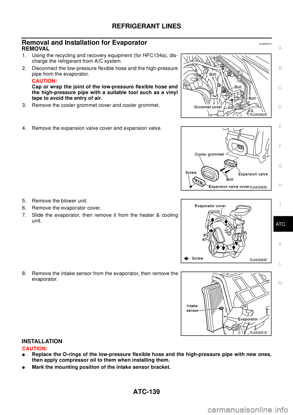
Removal and Installation for EvaporatorEJS000VG
REMOVAL
1. Using the recycling and recovery equipment (for HFC134a), dis-
charge the refrigerant from A/C system.
2. Disconnect the low-pressure flexible hose and the high-pressure
pipe from the evaporator.
CAUTION:
Cap or wrap the joint of the low-pressure flexible hose and
the high-pressure pipe with a suitable tool such as a vinyl
tape to avoid the entry of air.
3. Remove the cooler grommet cover and cooler grommet.
4. Remove the expansion valve cover and expansion valve.
5. Remove the blower unit.
6. Remove the evaporator cover.
7. Slide the evaporator, then remove it from the heater & cooling
unit.
8. Remove the intake sensor from the evaporator, then remove the
evaporator.
INSTALLATION
CAUTION:
lReplace the O-rings of the low-pressure flexible hose and the high-pressure pipe with new ones,
then apply compressor oil to them when installing them.
lMark the mounting position of the intake sensor bracket.
RJIA0082E
RJIA0083E
RJIA0084E
RJIA0051E