2003 NISSAN X-TRAIL sensor
[x] Cancel search: sensorPage 766 of 3066
BL-22
POWER DOOR LOCK SYSTEM
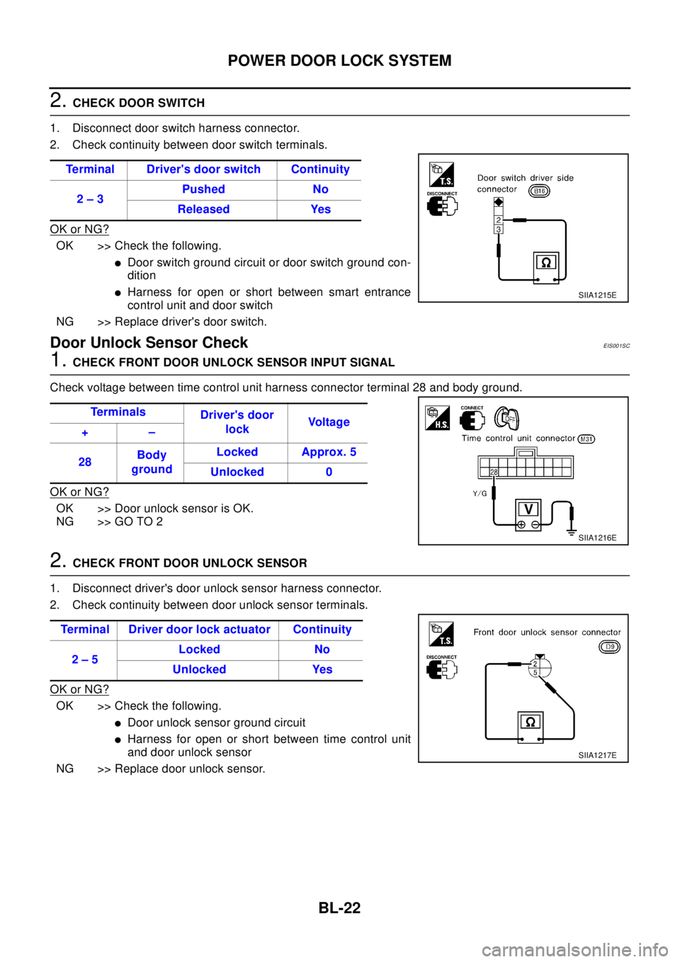
2.CHECK DOOR SWITCH
1. Disconnect door switch harness connector.
2. Check continuity between door switch terminals.
OK or NG?
OK >> Check the following.
lDoor switch ground circuit or door switch ground con-
dition
lHarness for open or short between smart entrance
control unit and door switch
NG >> Replace driver's door switch.
Door Unlock Sensor CheckEIS001SC
1.CHECK FRONT DOOR UNLOCK SENSOR INPUT SIGNAL
Check voltage between time control unit harness connector terminal 28 and body ground.
OK or NG?
OK >> Door unlock sensor is OK.
NG >> GO TO 2
2.CHECK FRONT DOOR UNLOCK SENSOR
1. Disconnect driver's door unlock sensor harness connector.
2. Check continuity between door unlock sensor terminals.
OK or NG?
OK >> Check the following.
lDoor unlock sensor ground circuit
lHarness for open or short between time control unit
and door unlock sensor
NG >> Replace door unlock sensor.Terminal Driver's door switch Continuity
2–3Pushed No
Released Yes
SIIA1215E
Te r m i n a l s
Driver's door
lockVo l t a g e
+–
28Body
groundLocked Approx. 5
Unlocked 0
SIIA1216E
Terminal Driver door lock actuator Continuity
2–5Locked No
Unlocked Yes
SIIA1217E
Page 769 of 3066

POWER DOOR LOCK — SUPER LOCK —
BL-25
C
D
E
F
G
H
J
K
L
MA
B
BL
Lock/unlock switch operation cannot control super lock
Key reminder system
lIf the ignition key is in the ignition key cylinder and driver door is open, setting lock/unlock switch, lock
knob, key or multi-remote controller to “LOCK” locks the door once but then immediately unlocks all doors.
(signal from door unlock sensor driver side)
System initialization
lSystem initialization is required when battery cables are reconnected. Conduct the following to release
super lock once;
–insert the key into the ignition key cylinder and turn it to ON.
–LOCK/UNLOCK operation using door key cylinder or multi-remote controller.
Page 779 of 3066
POWER DOOR LOCK — SUPER LOCK —
BL-35
C
D
E
F
G
H
J
K
L
MA
B
BL
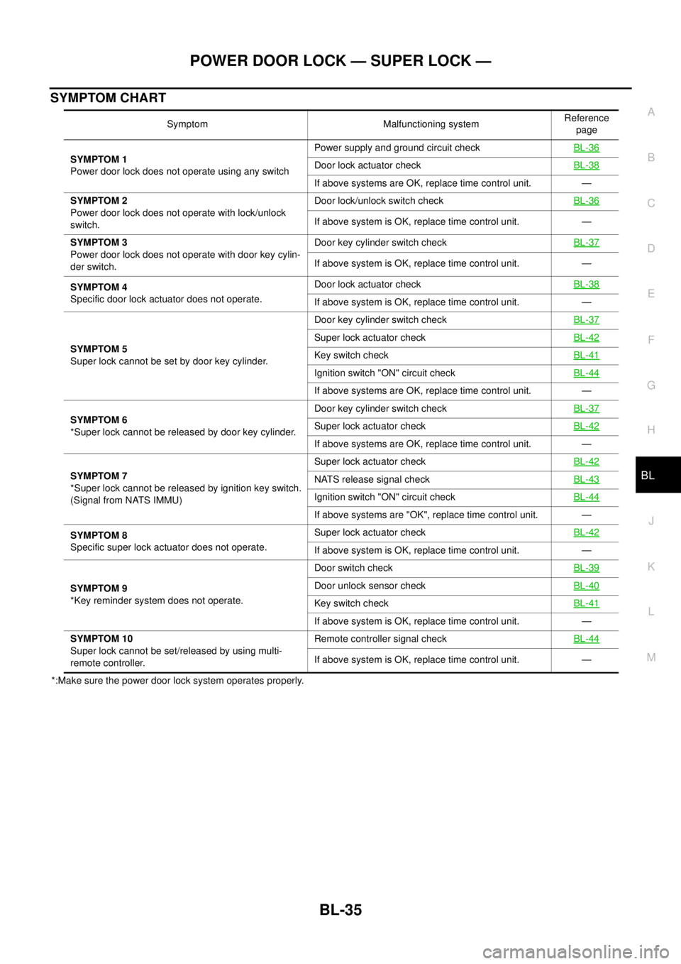
SYMPTOM CHART
*:Make sure the power door lock system operates properly.Symptom Malfunctioning systemReference
page
SYMPTOM 1
Power door lock does not operate using any switchPower supply and ground circuit checkBL-36
Door lock actuator checkBL-38
If above systems are OK, replace time control unit. —
SYMPTOM 2
Power door lock does not operate with lock/unlock
switch.Door lock/unlock switch checkBL-36
If above system is OK, replace time control unit. —
SYMPTOM 3
Power door lock does not operate with door key cylin-
der switch.Door key cylinder switch checkBL-37
If above system is OK, replace time control unit. —
SYMPTOM 4
Specific door lock actuator does not operate.Door lock actuator checkBL-38
If above system is OK, replace time control unit. —
SYMPTOM 5
Super lock cannot be set by door key cylinder.Door key cylinder switch checkBL-37
Super lock actuator checkBL-42
Key switch checkBL-41
Ignition switch "ON" circuit checkBL-44
If above systems are OK, replace time control unit. —
SYMPTOM 6
*Super lock cannot be released by door key cylinder.Door key cylinder switch checkBL-37
Super lock actuator checkBL-42
If above systems are OK, replace time control unit. —
SYMPTOM 7
*Super lock cannot be released by ignition key switch.
(Signal from NATS IMMU)Super lock actuator checkBL-42
NATS release signal checkBL-43
Ignition switch "ON" circuit checkBL-44
If above systems are "OK", replace time control unit. —
SYMPTOM 8
Specific super lock actuator does not operate.Super lock actuator checkBL-42
If above system is OK, replace time control unit. —
SYMPTOM 9
*Key reminder system does not operate.Door switch checkBL-39
Door unlock sensor checkBL-40
Key switch checkBL-41
If above system is OK, replace time control unit. —
SYMPTOM 10
Super lock cannot be set/released by using multi-
remote controller.Remote controller signal checkBL-44
If above system is OK, replace time control unit. —
Page 784 of 3066
BL-40
POWER DOOR LOCK — SUPER LOCK —
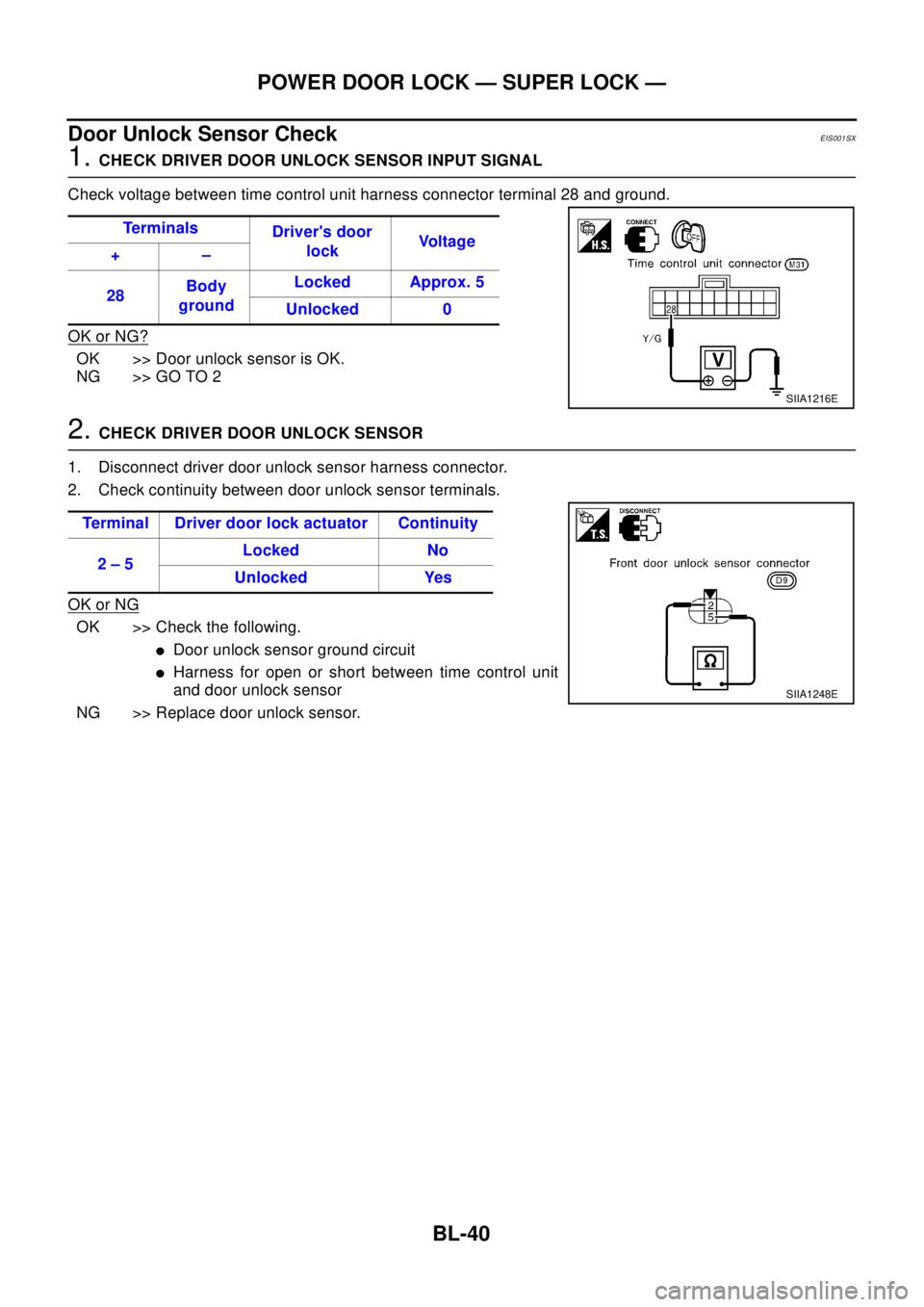
Door Unlock Sensor Check
EIS001SX
1.CHECK DRIVER DOOR UNLOCK SENSOR INPUT SIGNAL
Check voltage between time control unit harness connector terminal 28 and ground.
OK or NG?
OK >> Door unlock sensor is OK.
NG >> GO TO 2
2.CHECK DRIVER DOOR UNLOCK SENSOR
1. Disconnect driver door unlock sensor harness connector.
2. Check continuity between door unlock sensor terminals.
OK or NG
OK >> Check the following.
lDoor unlock sensor ground circuit
lHarness for open or short between time control unit
and door unlock sensor
NG >> Replace door unlock sensor.Te r m i n a l s
Driver's door
lockVo l t a g e
+–
28Body
groundLocked Approx. 5
Unlocked 0
SIIA1216E
Terminal Driver door lock actuator Continuity
2–5Locked No
Unlocked Yes
SIIA1248E
Page 790 of 3066
BL-46
MULTI-REMOTE CONTROL SYSTEM
lthrough multi-remote control unit terminal 5
lto time control unit terminal 32.
Then time control unit operates to lock doors and set super lock (models with super lock).
UNLOCK OPERATION
When the UNLOCK signal is input to multi-remote control unit (the antenna of the system is combined with
multi-remote control unit), ground is supplied
lthrough multi-remote control unit terminal 6
lto time control unit terminal 33.
Time control unit operates to unlock driver's door and release super lock (models with super lock).
Then, if an unlock signal is sent from the remote controller again within 5 seconds, all other doors will be
unlocked.
HAZARD REMINDER
When the doors are locked or unlocked by multi-remote controller (signal from driver side unlock sensor), sup-
ply power to hazard warning lamp flashes as follows
lLock operation: Flash once
lUnlock operation: Flash twice
MULTI-REMOTE CONTROLLER ID CODE ENTRY
A maximum of four remote controllers can be entered.
To enter ID code entry, the following signals must be input to the multi-remote control unit.
lIgnition switch (ON)
lSignal from remote controller
For detailed procedure, refer toBL-52, "
ID Code Entry Procedure".
Page 837 of 3066
PRECAUTIONS
BR-3
C
D
E
G
H
I
J
K
L
MA
B
BR
PRECAUTIONSPFP:00001
Precautions for Models with SRS Air Bag and Pre-Tensioner Seat BeltEFS000BY
WA RN ING:
lBefore removing and installing components and harnesses of SRS air bag and seat belt pre-ten-
sioner system, turn ignition switch OFF, disconnect battery ground cable, and wait at least 3 min-
utes. (This discharges electricity held in the air bag sensor unit's additional power circuit.)
lDo not use pneumatic or electric tools to remove and install the components.
lDo not solder SRS air bag and seat belt pre-tensioner system harnesses when making repairs.
Make sure harness is not pinched and there is no contact with other components.
lWhen checking the SRS air bag and the seat belt pre-tensioner circuit or the components of each
system, do not use an electric tester such as a circuit tester. (This is to prevent accidental trigger-
ing caused by the weak electric current of a tester.)
lNever insert foreign material (such as a screwdriver) in the air bag module and pre-tensioner seat
belt connectors. (The units may be actuated by mistake by static electricity.)
lSeat belt pre-tensioner and SRS air bag harnesses can be distinguished from other harnesses by
their yellow connectors.
lWhen servicing, refer to “SB Seat Belt” and “SRS Air Bag” for safety.
Precautions for Brake SystemEFS000BZ
lClean dust on brake pads, shoes, drums, and back plates with a vacuum dust collector. Do not blow with
compressed air.
lRecommended fluid is brake fluid “DOT 3” or “DOT 4”.
lNever reuse drained brake fluid.
lBe careful not to splash brake fluid on painted areas such as the body. If brake fluid is splashed or spilled
on paint, wipe it off and flush the area with water immediately.
lUse only clean brake fluid when cleaning master cylinder and disc brake components.
lNever use mineral oils such as gasoline or kerosene to clean. They will ruin the rubber parts and cause
improper operation.
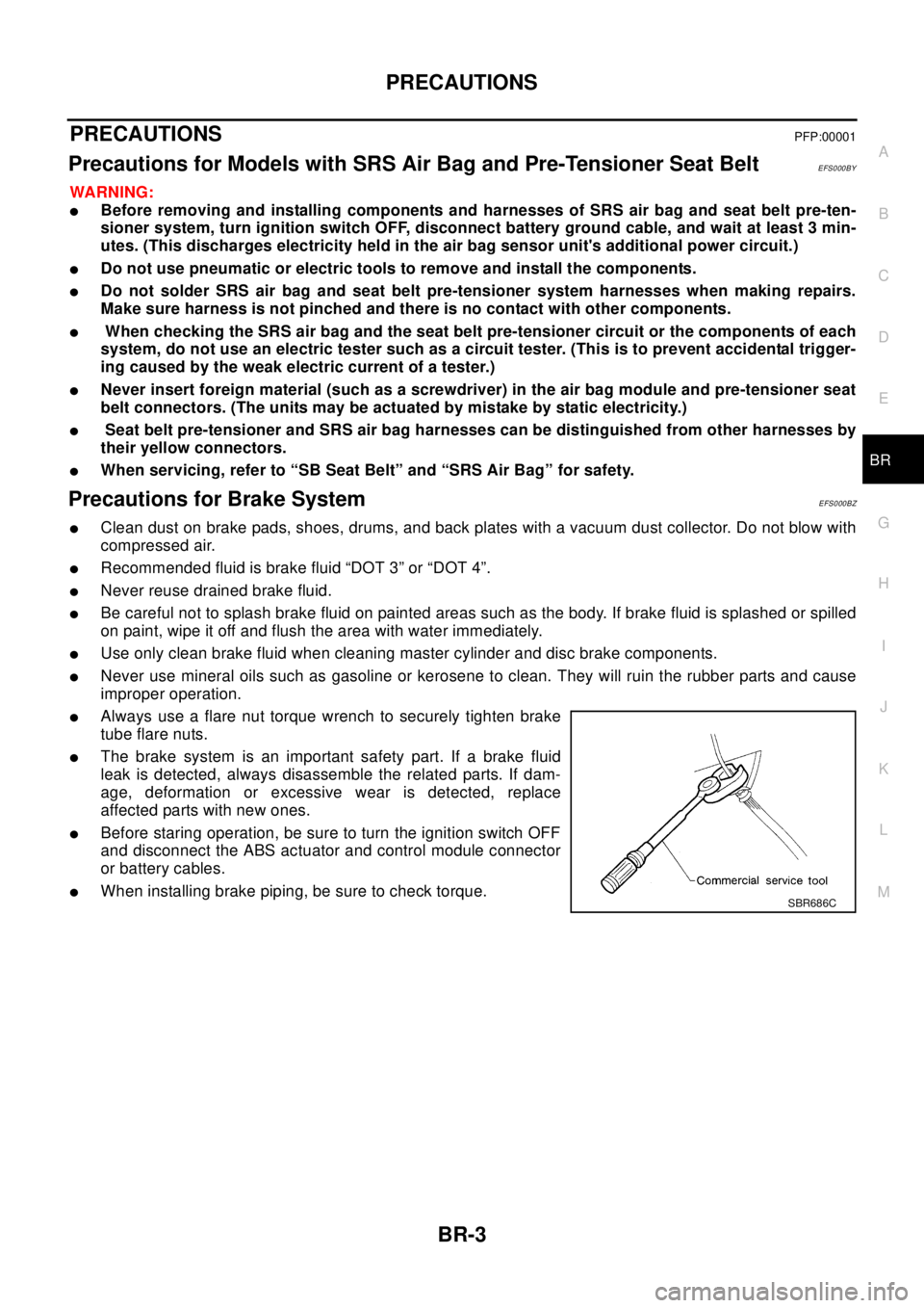
lAlways use a flare nut torque wrench to securely tighten brake
tube flare nuts.
lThe brake system is an important safety part. If a brake fluid
leak is detected, always disassemble the related parts. If dam-
age, deformation or excessive wear is detected, replace
affected parts with new ones.
lBefore staring operation, be sure to turn the ignition switch OFF
and disconnect the ABS actuator and control module connector
or battery cables.
lWhen installing brake piping, be sure to check torque.SBR686C
Page 847 of 3066
BRAKE MASTER CYLINDER
BR-13
C
D
E
G
H
I
J
K
L
MA
B
BR
BRAKE MASTER CYLINDERPFP:46010
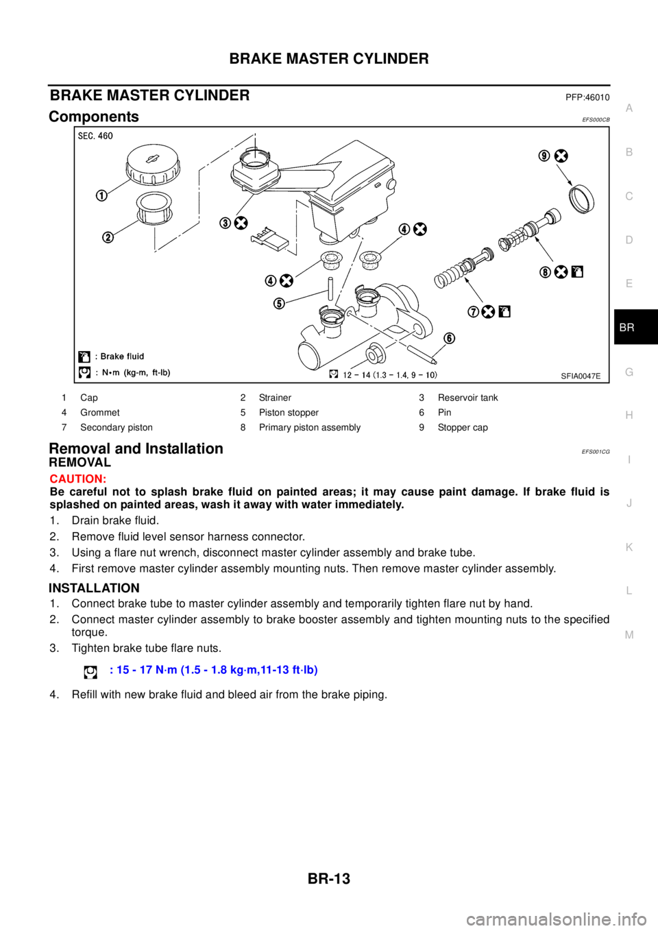
ComponentsEF S0 00 CB
Removal and InstallationEFS001CG
REMOVAL
CAUTION:
Be careful not to splash brake fluid on painted areas; it may cause paint damage. If brake fluid is
splashed on painted areas, wash it away with water immediately.
1. Drain brake fluid.
2. Remove fluid level sensor harness connector.
3. Using a flare nut wrench, disconnect master cylinder assembly and brake tube.
4. First remove master cylinder assembly mounting nuts. Then remove master cylinder assembly.
INSTALLATION
1. Connect brake tube to master cylinder assembly and temporarily tighten flare nut by hand.
2. Connect master cylinder assembly to brake booster assembly and tighten mounting nuts to the specified
torque.
3. Tighten brake tube flare nuts.
4. Refill with new brake fluid and bleed air from the brake piping.
SFIA0047E
1 Cap 2 Strainer 3 Reservoir tank
4 Grommet 5 Piston stopper 6 Pin
7 Secondary piston 8 Primary piston assembly 9 Stopper cap
:15-17N·m(1.5-1.8kg·m,11-13ft·lb)
Page 869 of 3066
BRC-1
BRAKE CONTROL SYSTEM
F BRAKES
CONTENTS
C
D
E
G
H
I
J
K
L
M
SECTION
A
B
BRC
BRAKE CONTROL SYSTEM
4WD/ABS
PRECAUTIONS .......................................................... 4
Precautions for brake system ................................... 4
Precautions for brake control ................................... 4
PREPARATION ........................................................... 5
Special Service Tools ............................................... 5
ALL MODE 4X4 SYSTEM .......................................... 6
System Description .................................................. 6
ABS FUNCTION ................................................... 6
4WD FUNCTION ................................................... 6
Control System Diagram .......................................... 6
TROUBLE DIAGNOSIS .............................................. 7
Fail-safe Function ..................................................... 7
How to Proceed with Trouble Diagnosis .................. 7
BASIC CONCEPT ................................................. 7
DIAGNOSIS FLOW ............................................... 8
ASKING COMPLAINTS ........................................ 9
TROUBLE DIAGNOSIS SHEET - EXAMPLE ....... 9
Component Parts Location ..................................... 10
Schematic ...............................................................11
Wiring Diagram — ABS — ..................................... 12
Trouble Diagnosis Chart by Symptom .................... 18
4WD/ABS Control Unit Input/Output Signal Stan-
dard ........................................................................ 19
4WD/ABS CONTROL UINT CONNECTOR TER-
MINAL ARRANGEMENT .................................... 19
REFERENCE STANDARD TABLE ..................... 19
CONSULT-II Functions ........................................... 23
CONSULT-II FUNCTION APPLICATION TABLE... 23
SELF-DIAGNOSIS .............................................. 24
DATA MONITOR ................................................. 26
ACTIVE TEST ..................................................... 29
Component Inspection ........................................... 30
ABS ACTUATOR ................................................ 30
4WD SOLENOID VALVE .................................... 32
Basic Inspection ..................................................... 32
BASIC INSPECTION 1 BRAKE FLUID LEVEL
AND LEAKAGE INSPECTION ............................ 32
BASIC INSPECTION 2 INSPECTION FOR
LOOSE POWER SUPPLY TERMINAL ............... 32BASIC INSPECTION 3 ABS/4WD WARNING
LAMP INSPECTION ............................................ 32
Wheel Speed Sensor System ................................. 32
INSPECTION PROCEDURE .............................. 32
Control Module Power Supply System ................... 34
INSPECTION PROCEDURE .............................. 34
G -Sensor System (4WD models) .......................... 34
INSPECTION PROCEDURE .............................. 34
4WD SOLENOID, ACTUATOR RELAY SYSTEM... 35
4WD MODE SWITCH SYSTEM ............................. 37
Trouble Diagnoses for Symptoms .......................... 38
4WD INDICATOR LAMP DOES NOT COME ON
FORAPPROXIMATELY1SECONDWHENTHE
IGNITION SWITCH IS TURNED TO ON ............. 38
4WD WARNING LAMP DOES NOT ILLUMINATE
WITH IGNITION ON ............................................ 39
4WD WARNING LAMP DOES NOT GO OUT
SEVERAL SECONDS AFTER ENGINE
STARTED.(4WD MODE INDICATOR LAMP
GOES OUT) ........................................................ 39
HEAVY TIGHT-CORNER BRAKING SYMPTOM
OCCURS WHEN THE VEHICLE IS DRIVEN IN
AUTO MODE AND THE STEERING WHEEL IS
TURNED FULLY TO EITHER SIDE AFTER THE
ENGINE IS STARTED ......................................... 39
4WD MODES CANNOT BE SWITCHED AFTER
ENGINE IS STARTED ......................................... 41
WHILE DRIVING, 4WD WARNING LAMP
FLASHES RAPIDLY. (WHEN IT FLASHERSFOR
APPROX. ONE MINUTE, THEN DOES NOT
ILLUMINATE.) ..................................................... 41
WHILE DRIVING, 4WD WARNING LAMP
FLASHES SLOWLY. (WHEN IT CONTINUES TO
ILLUMINATE UNTIL ENGINE TURNS OFF.) ...... 41
VEHICLE DOES NOT ENTER 4WD MODE
EVEN THOUGH 4WD WARNING LAMP IS OFF.... 41
TIGHT-CONER BRAKING SYMPTOM OCCURS
WHEN THE VEHICLE IS STARTED IN AUTO
WARNING LAMP REMAIN OFF). ....................... 42
4WD ACTUATOR RELAY (4WD SOLENOID