Page 298 of 3502

AT-290
REPAIR FOR COMPONENT PARTS
DISASSEMBLY
1. Remove valves at retainer plates.
CAUTION:
Do not use a magnetic pick-up tool.
a. Use a screwdriver to remove retainer plates.
b. Remove retainer plates while holding spring, plugs or sleeves.
CAUTION:
Remove plugs slowly to prevent internal parts from jumping
out.
1. Retainer plate 2. Plug 3. Cooler check valve spring
4. Cooler check valve 5. Control valve upper body 6. Pilot valve
7. Pilot valve spring 8. Retainer plate 9. 1-2 accumulator retainer plate
10. 1-2 accumulator piston spring 11. 1-2 accumulator piston 12. Plug
13. Retainer plate 14. Retainer plate 15. Plug
16. 1st reducing valve 17. 1st reducing valve spring 18. Retainer plate
19. 3-2 timing valve spring 20. 3-2 timing valve 21. Retainer plate
22. Plug 23. Overrun clutch reducing valve 24. Overrun clutch reducing valve spring
25. Retainer plate 26. Torque converter relief valve spring 27. Torque converter relief valve
28. Retainer plate 29. Sleeve 30. Plug
31. Torque converter clutch control valve
spring32. Torque converter clutch control
valve33. Retainer plate
34. Plug 35. 1-2 accumulator valve spring 36. 1-2 accumulator valve
SCIA4979E
SAT553G
SAT554G
Page 300 of 3502
AT-292
REPAIR FOR COMPONENT PARTS
–Wrap a small screwdriver with vinyl tape and use it to insert
valves into their proper positions.
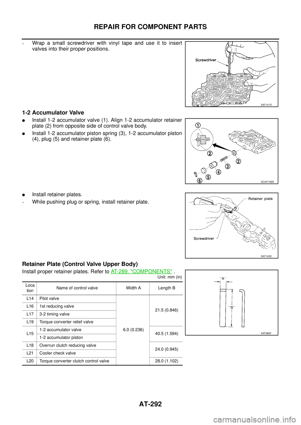
1-2 Accumulator Valve
�Install 1-2 accumulator valve (1). Align 1-2 accumulator retainer
plate (2) from opposite side of control valve body.
�Install 1-2 accumulator piston spring (3), 1-2 accumulator piston
(4), plug (5) and retainer plate (6).
�Install retainer plates.
–While pushing plug or spring, install retainer plate.
Retainer Plate (Control Valve Upper Body)
Install proper retainer plates. Refer to AT- 2 8 9 , "COMPONENTS" .
Unit: mm (in)
SAT141D
SCIA7182E
SAT143D
Loca
tionName of control valve Width A Length B
L14 Pilot valve
6.0 (0.236)21.5 (0.846) L16 1st reducing valve
L17 3-2 timing valve
L19 Torque converter relief valve
L151-2 accumulator valve
40.5 (1.594)
1-2 accumulator piston
L18 Overrun clutch reducing valve
24.0 (0.945)
L21 Cooler check valve
L20 Torque converter clutch control valve 28.0 (1.102)
SAT086F
Page 346 of 3502

AT-338
REPAIR FOR COMPONENT PARTS
b. Move side gear up and down to measure dial indicator deflec-
tion. Always measure indicator deflection on both side gears.
c. If not within specification, adjust clearance by changing thick-
ness of differential side gear thrust washers. Refer to “Parts
Information” for side gear thrust washers selection.
4. Install lock pin with pin punch.
CAUTION:
�Do not reuse lock pin.
�Make sure that lock pin is flush with differential case.
5. Press on differential side bearings.
CAUTION:
Apply ATF to differential side bearings.
6. Install differential side bearing outer race and differential side
bearing adjusting shim on transaxle case. Refer to AT- 3 4 0 ,
"Adjustment (1)" .
7. Tighten final gear and tighten fixing bolts to the specified torque
in numerical order as shown in the figure after temporarily tight-
ening them. Refer to AT- 3 3 5 , "
COMPONENTS" . Clearance between side gear and differential
case with washer:
Refer to AT- 3 6 7 , "
Final Drive" .
SMT611A
SAT904DA
SAT545FA
ATM0432D
Page 347 of 3502
ASSEMBLY
AT-339
D
E
F
G
H
I
J
K
L
MA
B
AT
ASSEMBLYPFP:00000
Assembly (1)BCS001OW
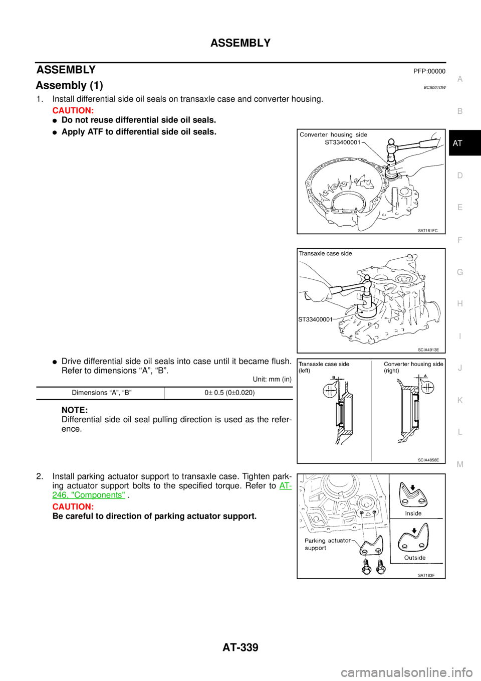
1. Install differential side oil seals on transaxle case and converter housing.
CAUTION:
�Do not reuse differential side oil seals.
�Apply ATF to differential side oil seals.
�Drive differential side oil seals into case until it became flush.
Refer to dimensions “A”, “B”.
Unit: mm (in)
NOTE:
Differential side oil seal pulling direction is used as the refer-
ence.
2. Install parking actuator support to transaxle case. Tighten park-
ing actuator support bolts to the specified torque. Refer to AT-
246, "Components" .
CAUTION:
Be careful to direction of parking actuator support.
SAT181FC
SCIA4913E
Dimensions “A”, “B” 0± 0.5 (0±0.020)
SCIA4858E
SAT183F
Page 348 of 3502
AT-340
ASSEMBLY
3. Install parking pawl on transaxle case and fix it with parking
shaft.
4. Install return spring and parking pawl spacer.
Adjustment (1)BCS001OX
DIFFERENTIAL SIDE BEARING PRELOAD
1. Install differential side bearing outer race without differential side
bearing adjusting shim on transaxle case.
CAUTION:
Apply ATF to differential side bearing outer race.
2. Install differential side bearing outer race on converter housing.
CAUTION:
Apply ATF to differential side bearing outer race.
3. Place final drive assembly on transaxle case.
4. Install converter housing on transaxle case. Tighten converter
housing mounting bolts to the specified torque. Refer to AT- 2 4 6 ,
"Components" .
SCIA4881E
SAT870D
SAT008F
Page 349 of 3502

ASSEMBLY
AT-341
D
E
F
G
H
I
J
K
L
MA
B
AT
5. Attach dial indicator on differential case at converter housing
side.
6. Insert SST into differential side gear from transaxle case side.
7. Move SST up and down and measure dial indicator deflection.
8. Select proper thickness of differential side bearing adjusting
shim. Refer to “Parts Information” for differential side bearing
adjusting shim selection.
Suitable shim thickness = Dial indicator deflection + Speci-
fied bearing preload
9. Remove converter housing from transaxle case.
10. Remove final drive assembly from transaxle case.
11. Remove differential side bearing outer race from transaxle case.
12. Reinstall differential side bearing outer race and differential side
bearing adjusting shim selected from “Parts Information” on
transaxle case.
13. Reinstall converter housing on transaxle case and tighten con-
verter housing mounting bolts to the specified torque. Refer to
AT- 2 4 6 , "
Components" .
14. Insert SST and measure turning torque of final drive assembly.
�Turn final drive assembly in both directions several times
to seat bearing rollers correctly.
�When old bearing is used again, turning torque will be
slightly less than the above.
�Make sure torque is close to the specified range.
REDUCTION PINION GEAR BEARING PRELOAD
1. Remove converter housing and final drive assembly from tran-
saxle case.
2. Select proper thickness of reduction pinion gear bearing adjust-
ing shim using the following procedures.
a. Place reduction pinion gear on transaxle case as shown.Suitable shim thickness = Dial indicator deflection +
Specified bearing preload
Bearing preload: Refer to AT- 3 6 7 , "
Final Drive" .
SAT186FA
SAT010FC
Turning torque of final drive assembly
(New bearing):
Refer to AT- 3 6 7 , "
Final Drive" .
SCIA4914E
SCIA3623E
Page 351 of 3502

ASSEMBLY
AT-343
D
E
F
G
H
I
J
K
L
MA
B
AT
3. Install reduction pinion gear and reduction pinion gear bearing
adjusting shim selected in step 2-e on transaxle case.
4. Press idler gear bearing inner race on idler gear. Refer to AT-
337, "ASSEMBLY" .
5. Press idler gear on reduction pinion gear.
CAUTION:
Press idler gear until idler gear fully contacts adjusting
shim.
6. Set manual shaft to “P” position to fix idler gear.
7. Tighten idler gear lock nut to the specified torque. Refer to AT-
246, "Components" .
CAUTION:
Lock idler gear with parking pawl when tightening lock nut.
8. Measure turning torque of reduction pinion gear.
�When measuring turning torque, turn reduction pinion
gear in both directions several times to seat bearing roll-
ers correctly.
�If turning torque is out of specification, decrease or
increase thickness of reduction pinion gear adjusting
shim.
9. After properly adjusting turning torque, clinch idler gear lock nut
as shown.
CAUTION:
Do not reuse idler gear lock nut.
SAT873DE
SAT189F
Turning torque of reduction pinion gear:
Refer to AT- 3 6 7 , "
Reduction Pinion Gear" .
SAT190FB
SCIA4915E
Page 354 of 3502
AT-346
ASSEMBLY
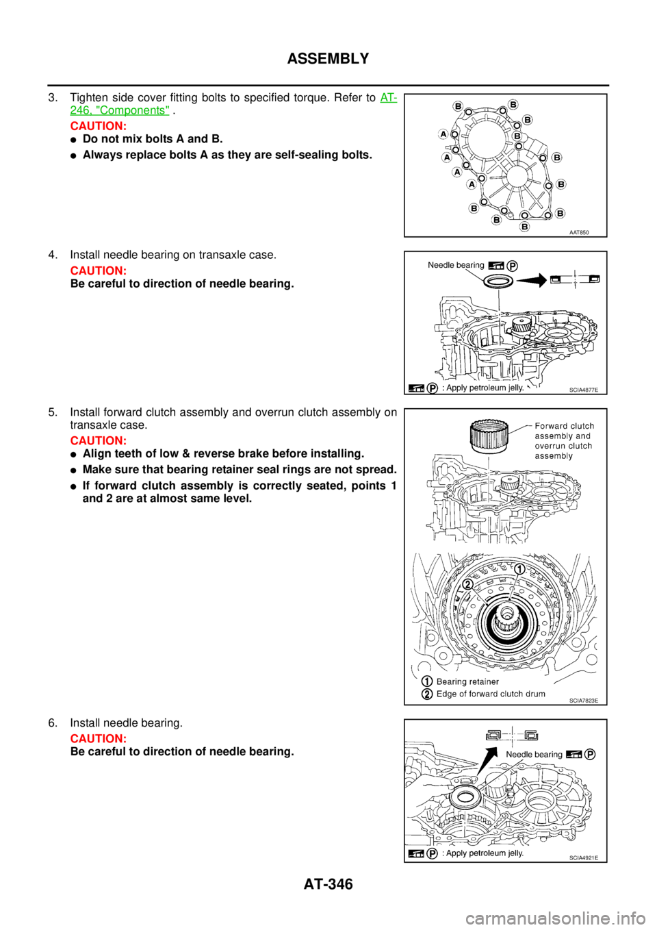
3. Tighten side cover fitting bolts to specified torque. Refer to AT-
246, "Components" .
CAUTION:
�Do not mix bolts A and B.
�Always replace bolts A as they are self-sealing bolts.
4. Install needle bearing on transaxle case.
CAUTION:
Be careful to direction of needle bearing.
5. Install forward clutch assembly and overrun clutch assembly on
transaxle case.
CAUTION:
�Align teeth of low & reverse brake before installing.
�Make sure that bearing retainer seal rings are not spread.
�If forward clutch assembly is correctly seated, points 1
and 2 are at almost same level.
6. Install needle bearing.
CAUTION:
Be careful to direction of needle bearing.
AAT850
SCIA4877E
SCIA7823E
SCIA4921E
BCS001OX
DIFFERENTIAL SIDE BEARING PRELOAD
1.")