Page 253 of 3502

TRANSAXLE ASSEMBLY
AT-245
D
E
F
G
H
I
J
K
L
MA
B
AT
�Align the positions of tightening bolts for drive plate with those of
torque converter, and temporarily tighten bolts. Then, tighten
bolts with the specified torque.
CAUTION:
�When turning crankshaft, turn it clockwise as viewed from
front of engine.
�When tightening the tighten bolts for the torque converter
after fixing crankshaft pulley bolts, be sure to confirm the
tightening torque of crankshaft pulley mounting bolts.
Refer to EM-53, "
TIMING CHAIN" (QR engine), EM-173, "TIMING CHAIN" (VQ engine).
� After converter is installed to drive plate, rotate crankshaft several turns and make sure that tran-
saxle rotates freely without binding.
�Install POS sensor. Refer to EM-145, "Removal and Installation" .
�After completing installation, check for A/T fluid leakage, A/T fluid level, and positions of A/T. Refer to AT-
14, "Checking A/T Fluid" , AT- 2 1 5 , "Adjustment of A/T Position" , AT- 2 1 5 , "Checking of A/T Position" . : 52 N·m (5.3 kg-m, 38 ft-lb)
SCIA3138E
Page 255 of 3502
OVERHAUL
AT-247
D
E
F
G
H
I
J
K
L
MA
B
AT
1. Differential side bearing 2. Pinion mate gear thrust washer 3. Pinion mate gear
4. Pinion mate shaft 5. Lock pin 6. Side gear
7. Side gear thrust washer 8. Differential side bearing 9. Differential case
10. Final gear 11. Differential side bearing adjusting
shim12. Plug
13. O-ring 14. RH differential side oil seal 15. Torque converter
16. Converter housing 17. Differential lubricant tube 18. Clip
19. O-ring 20. Oil pump housing oil seal 21. Oil pump housing
22. O-ring 23. Outer gear 24. Inner gear
25. Oil pump cover 26. Oil pump assembly 27. Seal ring
28. Gasket
Page 263 of 3502
DISASSEMBLY
AT-255
D
E
F
G
H
I
J
K
L
MA
B
AT
DISASSEMBLYPFP:31020
DisassemblyBCS001OI
1. Drain ATF through drain plug.
2. Remove drain plug gasket from drain plug.
3. Remove torque converter.
4. Check torque converter one-way clutch using check tool as
shown in the figure.
a. Insert check tool into groove of bearing support built into one-
way clutch outer race.
b. When fixing bearing support with check tool, rotate one- way
clutch spline using screwdriver.
c. Check that inner race rotates clockwise only. If not, replace
torque converter assembly.
SCIA0003E
SAT008D
SAT009D
Page 282 of 3502
AT-274
REPAIR FOR COMPONENT PARTS
3. Install manual shaft to transaxle case, and install manual plate
to manual shaft.
4. Install parking rod plate (with parking rod) on manual shaft.
5. Align groove of manual shaft and hole of transaxle case with pin
punch.
6. Drive retaining pin of manual shaft with pin punch.
CAUTION:
Do not reuse retaining pin.
7. Set parking rod plate onto manual shaft, and drive retaining pin
of parking rod plate with pin punch.
CAUTION:
�Do not reuse retaining pin.
�Both ends of pin should protrude.
8. Set manual plate onto manual shaft, and drive retaining pin of
manual plate with pin punch.
CAUTION:
�Do not reuse retaining pin.
�Both ends of pin should protrude.
9. Install detent spring on transaxle case. Tighten detente spring
fitting bolt to the specified torque. Refer to AT- 2 7 2 , "
COMPO-
NENTS" .
SCIA3627E
SAT045FC
SAT034JA
SAT047FC
SAT042F
Page 286 of 3502
AT-278
REPAIR FOR COMPONENT PARTS
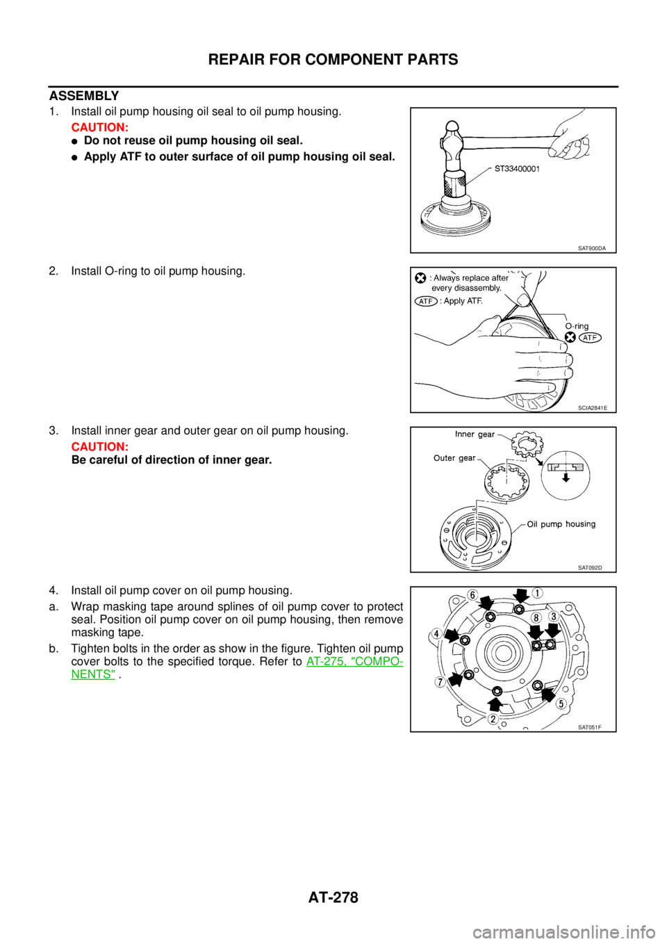
ASSEMBLY
1. Install oil pump housing oil seal to oil pump housing.
CAUTION:
�Do not reuse oil pump housing oil seal.
�Apply ATF to outer surface of oil pump housing oil seal.
2. Install O-ring to oil pump housing.
3. Install inner gear and outer gear on oil pump housing.
CAUTION:
Be careful of direction of inner gear.
4. Install oil pump cover on oil pump housing.
a. Wrap masking tape around splines of oil pump cover to protect
seal. Position oil pump cover on oil pump housing, then remove
masking tape.
b. Tighten bolts in the order as show in the figure. Tighten oil pump
cover bolts to the specified torque. Refer to AT- 2 7 5 , "
COMPO-
NENTS" .
SAT900DA
SCIA2841E
SAT092D
SAT051F
Page 292 of 3502
AT-284
REPAIR FOR COMPONENT PARTS
�Check to see that retainer plates are properly positioned in con-
trol valve upper body.
Oil Strainer
Check wire netting of oil strainer for damage. Replace if necessary.
Shift Solenoid Valves “A” and “B”, Line Pressure Solenoid Valve, Torque Converter Clutch
Solenoid Valve and Overrun Clutch Solenoid Valve
Measure resistance.
A/T Fluid Temperature Sensor
Measure resistance.
SCIA4979E
SCIA3291E
Item TerminalResistance
(Approx.)
Shift solenoid valve A 2 Ground 20 - 30 Ω
Shift solenoid valve B 1 Ground 5 - 20Ω
Line pressure solenoid valve 4 Ground 2.5 - 5.0Ω
Torque converter clutch
solenoid valve5Ground5 - 20Ω
Overrun clutch solenoid
valve3 Ground 20 - 30Ω
SCIA7532E
Item Terminal Temperature°C (°F)Resistance
(Approx.)
A/T fluid tem-
perature sensor6 - 720 (68) 2.5 kΩ
80 (176) 0.3 kΩ
SCIA7533E
Page 295 of 3502
REPAIR FOR COMPONENT PARTS
AT-287
D
E
F
G
H
I
J
K
L
MA
B
AT
2. Install O-rings (1) to solenoid valves and terminal body.
3. Install and tighten bolts.
Bolt length, number and location:
f: Reamer bolt and nut.
a. Install and tighten bolts b and nut f to specified torque.
SCIA7819E
Bolt symbolabcde f g
Bolt length “ ” mm (in)
13.5
(0.531)58.0
(2.283) 40.0
(1.575)66.0
(2.598)33.0
(1.299)78.0
(3.071)18.0
(0.709)
Number of bolts 6 3 6 11 2 2 1
Tightening torque
N·m (kg-m, in-lb)7.8 (0.80, 69)4.0
(0.41, 35)7.8 (0.80, 69)
SCIA4974E
: 7.8 N·m (0.80 kg-m, 69 in-lb)
SCIA4437E
Page 296 of 3502
AT-288
REPAIR FOR COMPONENT PARTS
b. Install solenoid valve assembly and line pressure solenoid valve
to control valve assembly.
c. Tighten bolts a , c and g to specified torque.
d. Set oil strainer, then tighten bolts a , d and nut f to specified
torque.
e. Tighten bolts e to specified torque. : 7.8 N·m (0.80 kg-m, 69 in-lb)
SCIA4438E
: 7.8 N·m (0.80 kg-m, 69 in-lb)
SCIA3484E
: 4.0 N·m (0.41 kg-m, 35 in-lb)
SCIA3487E


 on manual shaft.
5. Align groov")

 to solenoid valves and terminal body.
3. Install and tighten bolts.
Bolt length, number and location:
f: Reamer bol")
