Page 3247 of 3502
CHARGING SYSTEM
SC-29
C
D
E
F
G
H
I
J
L
MA
B
SC
Trouble DiagnosisBKS001ML
Before performing an alternator test, make sure that the battery is fully charged. A 30-volt voltmeter and suit-
able test probes are necessary for the test. The alternator can be checked easily by referring to the Inspection
Table.
�Before starting, inspect the fusible link.
�Use fully charged battery.
WITH IC REGULATOR
NOTE:
�If the inspection result is OK even though the charging system is malfunctioning, check the “B” terminal
connection (Check the tightening torque) and voltage drop.
�Check condition of rotor coil, rotor slip ring, brush and stator coil. If necessary, replace malfunctioning
parts with new ones.
SKIB0466E
Page 3260 of 3502

SE-4
PRECAUTIONS
PRECAUTIONSPFP:00001
Precautions for Supplemental Restraint System (SRS) “AIR BAG” and “SEAT
BELT PRE-TENSIONER”
BIS00129
The Supplemental Restraint System such as “AIR BAG” and “SEAT BELT PRE-TENSIONER”, used along
with a front seat belt, helps to reduce the risk or severity of injury to the driver and front passenger for certain
types of collision. Information necessary to service the system safely is included in the SRS and SB section of
this Service Manual.
WARNING:
�To avoid rendering the SRS inoperative, which could increase the risk of personal injury or death
in the event of a collision which would result in air bag inflation, all maintenance must be per-
formed by an authorized NISSAN/INFINITI dealer.
�Improper maintenance, including incorrect removal and installation of the SRS, can lead to per-
sonal injury caused by unintentional activation of the system. For removal of Spiral Cable and Air
Bag Module, see the SRS section.
�Do not use electrical test equipment on any circuit related to the SRS unless instructed to in this
Service Manual. SRS wiring harnesses can be identified by yellow and/or orange harnesses or
harness connectors.
Service NoticeBIS0012A
�When removing or installing various parts, place a cloth or padding onto the vehicle body to prevent
scratches.
�Handle trim, molding instruments, grille, etc. carefully during removing or installing. Be careful not to oil or
damage them.
�Apply sealing compound where necessary when installing parts.
�When applying sealing compound, be careful that the sealing compound does not protrude from parts.
�When replacing any metal parts (for example body outer panel, member, etc.), be sure to take rust pre-
vention measures.
Precautions BIS0012B
�When removing or disassembling any part, be careful not to damage or deform it. Protect parts, which
may get in the way with cloth.
�When removing parts with a screwdriver or other tool, protect parts by wrapping tools with vinyl or tape.
�Keep removed parts protected with cloth.
�If a clip is deformed or damaged, replace it.
�If an unreusable part is removed, replace it with a new one.
�Tighten bolts and nuts firmly to the specified torque.
�After re-assembly has been completed, make sure each part functions correctly.
�Remove stains in the following way.
Water-soluble stains:
Dip a soft cloth in warm water, and then squeeze it tightly. After wiping the stain, wipe with a soft dry cloth.
Oil stain:
Dissolve a synthetic detergent in warm water (density of 2 to 3% or less), dip the cloth, then clean off the stain
with the cloth. Next, dip the cloth in fresh water and squeeze it tightly. Then clean off the detergent completely.
Then wipe the area with a soft dry cloth.
�Do not use any organic solvent, such as thinner or benzine.
Page 3437 of 3502

ROAD WHEEL AND TYRE ASSEMBLY
WT-5
C
D
F
G
H
I
J
K
L
MA
B
WT
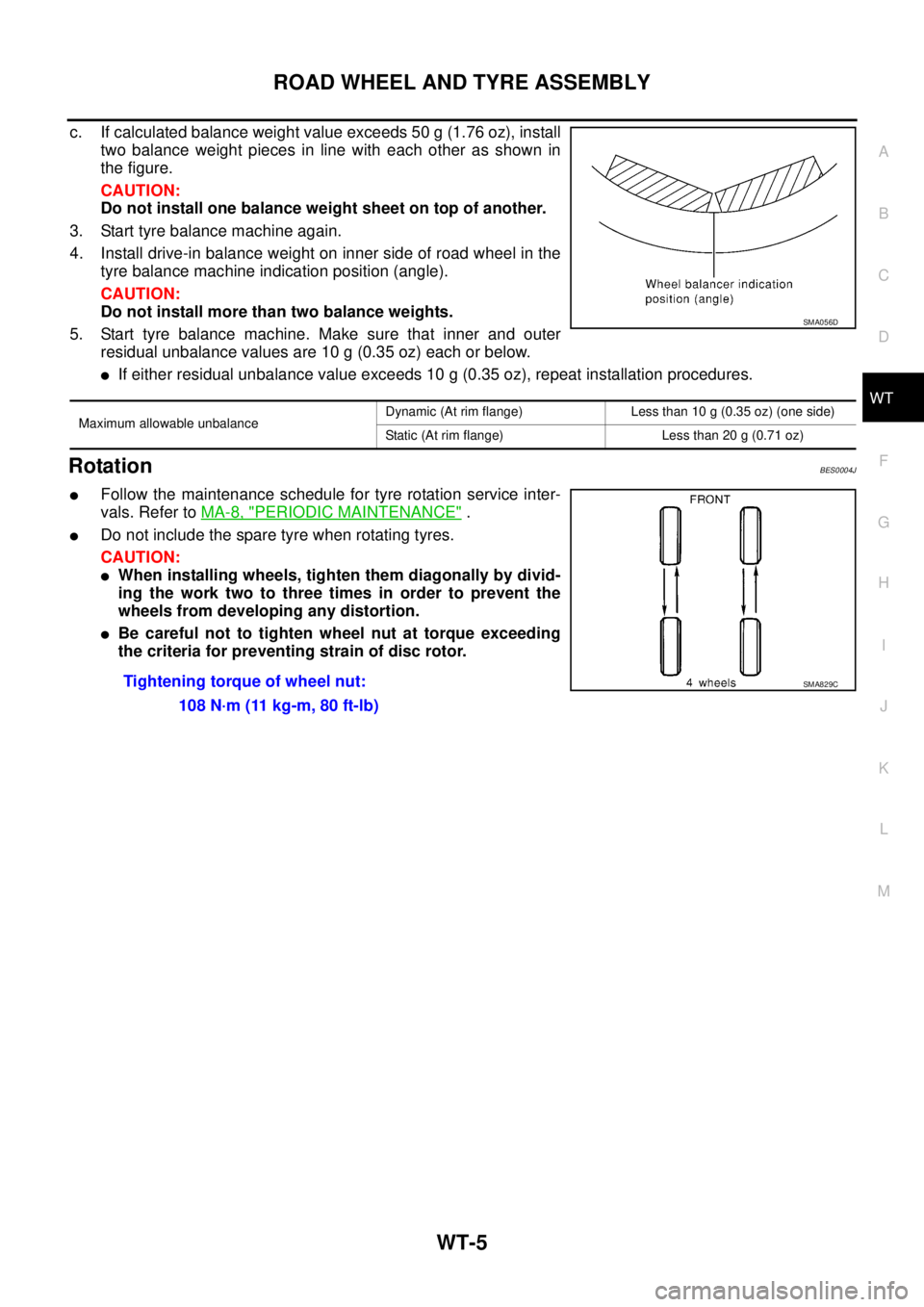
c. If calculated balance weight value exceeds 50 g (1.76 oz), install
two balance weight pieces in line with each other as shown in
the figure.
CAUTION:
Do not install one balance weight sheet on top of another.
3. Start tyre balance machine again.
4. Install drive-in balance weight on inner side of road wheel in the
tyre balance machine indication position (angle).
CAUTION:
Do not install more than two balance weights.
5. Start tyre balance machine. Make sure that inner and outer
residual unbalance values are 10 g (0.35 oz) each or below.
�If either residual unbalance value exceeds 10 g (0.35 oz), repeat installation procedures.
RotationBES0004J
�Follow the maintenance schedule for tyre rotation service inter-
vals. Refer to MA-8, "
PERIODIC MAINTENANCE" .
�Do not include the spare tyre when rotating tyres.
CAUTION:
�When installing wheels, tighten them diagonally by divid-
ing the work two to three times in order to prevent the
wheels from developing any distortion.
�Be careful not to tighten wheel nut at torque exceeding
the criteria for preventing strain of disc rotor.
Maximum allowable unbalanceDynamic (At rim flange) Less than 10 g (0.35 oz) (one side)
Static (At rim flange) Less than 20 g (0.71 oz)
SMA056D
Tightening torque of wheel nut:
108 N·m (11 kg-m, 80 ft-lb)SMA829C
Page 3472 of 3502

WW-34
FRONT WIPER AND WASHER SYSTEM
Removal and Installation of Front Wiper Arms, Adjustment of Wiper Arms Stop
Location
BKS003W6
REMOVAL
1. Turn front wiper switch ON to operate wiper motor, then turn front wiper switch OFF (auto stop).
2. Open hood, remove front wiper arm caps, and remove front wiper arm nuts.
3. Raise front wiper arms, and remove front wiper arms from the vehicle.
INSTALLATION
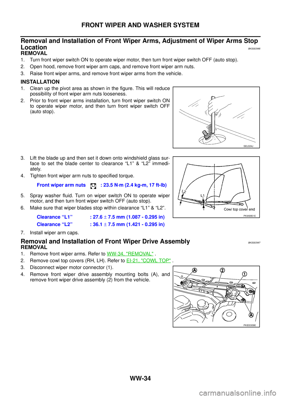
1. Clean up the pivot area as shown in the figure. This will reduce
possibility of front wiper arm nuts looseness.
2. Prior to front wiper arms installation, turn front wiper switch ON
to operate wiper motor, and then turn front wiper switch OFF
(auto stop).
3. Lift the blade up and then set it down onto windshield glass sur-
face to set the blade center to clearance “L1” & “L2” immedi-
ately.
4. Tighten front wiper arm nuts to specified torque.
5. Spray washer fluid. Turn on wiper switch ON to operate wiper
motor, and then turn front wiper switch OFF (auto stop).
6. Make sure that wiper blades stop within clearance “L1” & “L2”.
7. Install wiper arm caps.
Removal and Installation of Front Wiper Drive AssemblyBKS003W7
REMOVAL
1. Remove front wiper arms. Refer to WW-34, "REMOVAL" .
2. Remove cowl top covers (RH, LH). Refer to EI-21, "
COWL TOP" .
3. Disconnect wiper motor connector (1).
4. Remove front wiper drive assembly mounting bolts (A), and
remove front wiper drive assembly (2) from the vehicle.
SEL024J
Front wiper arm nuts : 23.5 N·m (2.4 kg-m, 17 ft-lb)
Clearance “L1” : 27.6 ± 7.5 mm (1.087 - 0.295 in)
Clearance “L2” : 36.1 ± 7.5 mm (1.421 - 0.295 in)
PKIA9951E
PKID0309E