Page 3399 of 3502

TROUBLE DIAGNOSIS
SRS-25
C
D
E
F
G
I
J
K
L
MA
B
SRS
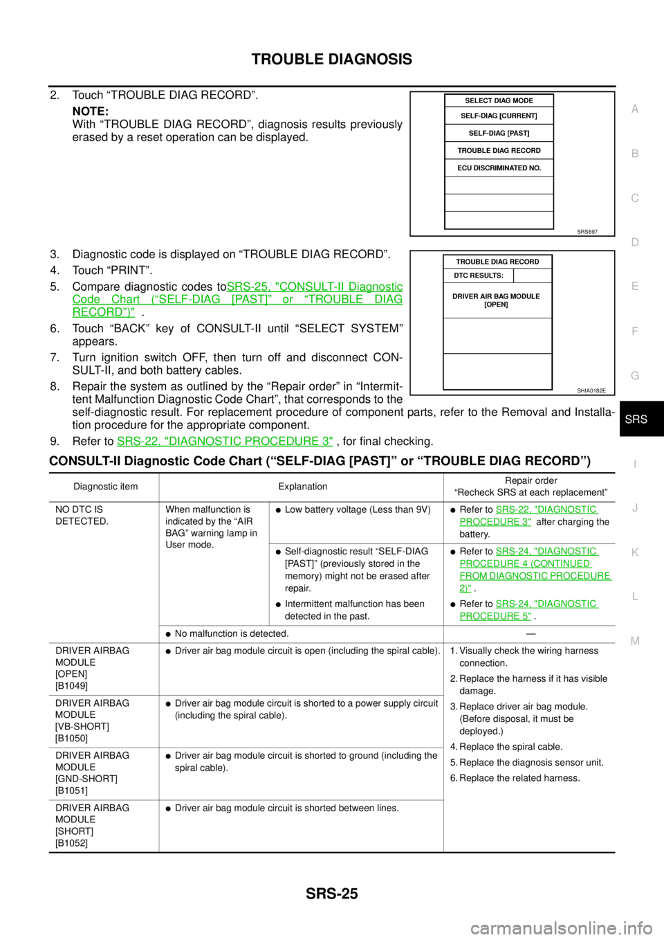
2. Touch “TROUBLE DIAG RECORD”.
NOTE:
With “TROUBLE DIAG RECORD”, diagnosis results previously
erased by a reset operation can be displayed.
3. Diagnostic code is displayed on “TROUBLE DIAG RECORD”.
4. Touch “PRINT”.
5. Compare diagnostic codes toSRS-25, "
CONSULT-II Diagnostic
Code Chart (“SELF-DIAG [PAST]” or “TROUBLE DIAG
RECORD”)" .
6. Touch “BACK” key of CONSULT-II until “SELECT SYSTEM”
appears.
7. Turn ignition switch OFF, then turn off and disconnect CON-
SULT-II, and both battery cables.
8. Repair the system as outlined by the “Repair order” in “Intermit-
tent Malfunction Diagnostic Code Chart”, that corresponds to the
self-diagnostic result. For replacement procedure of component parts, refer to the Removal and Installa-
tion procedure for the appropriate component.
9. Refer to SRS-22, "
DIAGNOSTIC PROCEDURE 3" , for final checking.
CONSULT-II Diagnostic Code Chart (“SELF-DIAG [PAST]” or “TROUBLE DIAG RECORD”)
SRS697
SHIA0182E
Diagnostic item ExplanationRepair order
“Recheck SRS at each replacement”
NO DTC IS
DETECTED.When malfunction is
indicated by the “AIR
BAG” warning lamp in
User mode.
�Low battery voltage (Less than 9V)�Refer to SRS-22, "DIAGNOSTIC
PROCEDURE 3" after charging the
battery.
�Self-diagnostic result “SELF-DIAG
[PAST]” (previously stored in the
memory) might not be erased after
repair.
�Intermittent malfunction has been
detected in the past.
�Refer to SRS-24, "DIAGNOSTIC
PROCEDURE 4 (CONTINUED
FROM DIAGNOSTIC PROCEDURE
2)" .
�Refer to SRS-24, "DIAGNOSTIC
PROCEDURE 5" .
�No malfunction is detected. —
DRIVER AIRBAG
MODULE
[OPEN]
[B1049]
�Driver air bag module circuit is open (including the spiral cable). 1. Visually check the wiring harness
connection.
2. Replace the harness if it has visible
damage.
3. Replace driver air bag module.
(Before disposal, it must be
deployed.)
4. Replace the spiral cable.
5. Replace the diagnosis sensor unit.
6. Replace the related harness. DRIVER AIRBAG
MODULE
[VB-SHORT]
[B1050]
�Driver air bag module circuit is shorted to a power supply circuit
(including the spiral cable).
DRIVER AIRBAG
MODULE
[GND-SHORT]
[B1051]
�Driver air bag module circuit is shorted to ground (including the
spiral cable).
DRIVER AIRBAG
MODULE
[SHORT]
[B1052]
�Driver air bag module circuit is shorted between lines.
Page 3431 of 3502

COLLISION DIAGNOSIS
SRS-57
C
D
E
F
G
I
J
K
L
MA
B
SRS
For Side CollisionBHS0004P
WHEN THE SIDE AIR BAG IS ACTIVATED IN A SIDE COLLISION:
1. Replace the following components:
–All parts of front seatback (including front seatback frame) with front side air bag module (on the side on
which front side air bag is activated)
–Curtain air bag module (on the side on which side curtain air bag is activated)
–Diagnosis sensor unit
–Satellite sensor (on the side on which side air bag and side curtain air bag are activated)
2. Check the SRS components and the related parts using the following table.
–Replace any SRS components and the related parts showing visible signs of damage (dents, cracks,
deformation).
3. Conduct self-diagnosis using CONSULT-II or “AIR BAG” warning lamp. Refer to SRS-16, "
SRS Operation
Check" . Ensure entire SRS operates properly.
WHEN SRS IS NOT ACTIVATED IN A SIDE COLLISION:
1. Check the SRS components and the related parts using the following table.
–Replace any SRS components and the related parts showing visible signs of damage (dents, cracks,
deformation).
2. Conduct self-diagnosis using CONSULT-II or “AIR BAG” warning lamp. Refer to SRS-16, "
SRS Operation
Check" . Ensure entire SRS operates properly.
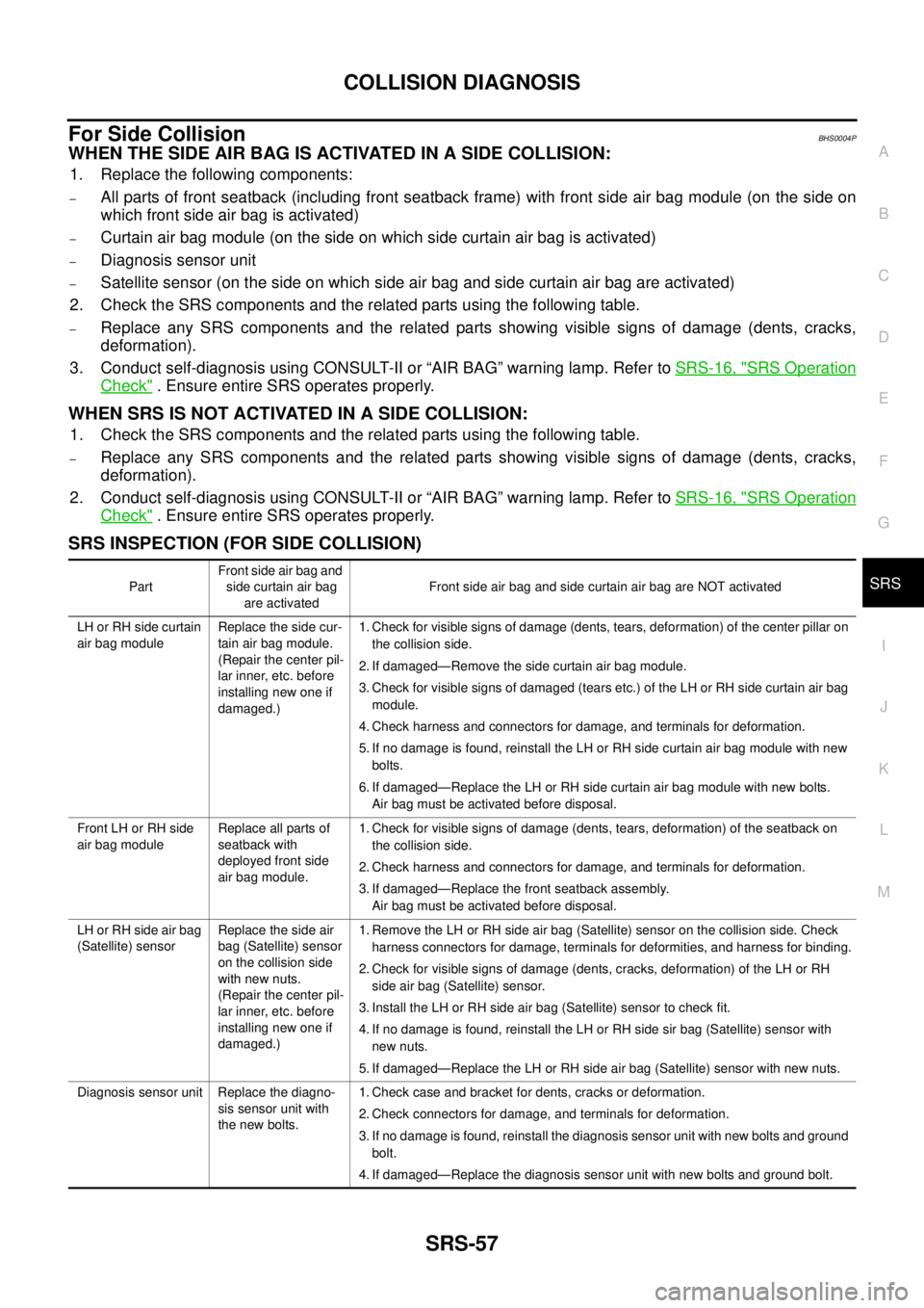
SRS INSPECTION (FOR SIDE COLLISION)
PartFront side air bag and
side curtain air bag
are activatedFront side air bag and side curtain air bag are NOT activated
LH or RH side curtain
air bag moduleReplace the side cur-
tain air bag module.
(Repair the center pil-
lar inner, etc. before
installing new one if
damaged.)1. Check for visible signs of damage (dents, tears, deformation) of the center pillar on
the collision side.
2. If damaged—Remove the side curtain air bag module.
3. Check for visible signs of damaged (tears etc.) of the LH or RH side curtain air bag
module.
4. Check harness and connectors for damage, and terminals for deformation.
5. If no damage is found, reinstall the LH or RH side curtain air bag module with new
bolts.
6. If damaged—Replace the LH or RH side curtain air bag module with new bolts.
Air bag must be activated before disposal.
Front LH or RH side
air bag moduleReplace all parts of
seatback with
deployed front side
air bag module.1. Check for visible signs of damage (dents, tears, deformation) of the seatback on
the collision side.
2. Check harness and connectors for damage, and terminals for deformation.
3. If damaged—Replace the front seatback assembly.
Air bag must be activated before disposal.
LH or RH side air bag
(Satellite) sensorReplace the side air
bag (Satellite) sensor
on the collision side
with new nuts.
(Repair the center pil-
lar inner, etc. before
installing new one if
damaged.)1. Remove the LH or RH side air bag (Satellite) sensor on the collision side. Check
harness connectors for damage, terminals for deformities, and harness for binding.
2. Check for visible signs of damage (dents, cracks, deformation) of the LH or RH
side air bag (Satellite) sensor.
3. Install the LH or RH side air bag (Satellite) sensor to check fit.
4. If no damage is found, reinstall the LH or RH side sir bag (Satellite) sensor with
new nuts.
5. If damaged—Replace the LH or RH side air bag (Satellite) sensor with new nuts.
Diagnosis sensor unit Replace the diagno-
sis sensor unit with
the new bolts.1. Check case and bracket for dents, cracks or deformation.
2. Check connectors for damage, and terminals for deformation.
3. If no damage is found, reinstall the diagnosis sensor unit with new bolts and ground
bolt.
4. If damaged—Replace the diagnosis sensor unit with new bolts and ground bolt.
Page 3495 of 3502
HEADLAMP WASHER
WW-57
C
D
E
F
G
H
I
J
L
MA
B
WW
Removal and Installation of Headlamp Washer NozzleBKS002EX
REMOVAL
1. Pull out headlamp washer nozzle from a bumper, remove pawl
(A), and remove headlamp washer nozzle cover (1).
2. Remove undercover one.
3. Remove fender protector. Refer to EI-23, "
FENDER PROTEC-
TOR" .
4. Remove front bumper. Refer to EI-14, "
FRONT BUMPER" .
5. Remove headlamp washer tube (1). Refer to WW-58, "
Removal
and Installation of Headlamp Washer Tube Connector" .
6. Removal headlamp washer nozzle retainer (A).
7. Removal headlamp washer nozzle bracket (2).
8. Remove headlamp washer nozzle assembly (3).
�The check valve is installed in headlamp washer nozzle
assembly.
�The check valve prevents backflow of washer fluid.
INSTALLATION
Installation is the reverse order of removal.
CAUTION:
When installing nozzle, there should be no packing twist, etc.
AdjustmentBKS002EY
PKIC9877E
PKIC9878E
PKIC9879E
a: 45° ±3°
b: 46° ±3°
c: 14° ±3°
d: 11° ±3°