Page 2388 of 3502
 and a wood
block, and then remove hub lock nut.")
FAX-6
FRONT WHEEL HUB AND KNUCKLE
7. Separate wheel hub and bearing assembly from drive shaft by
lightly tapping the end with a hammer (suitable tool) and a wood
block, and then remove hub lock nut. Remove wheel hub and
bearing assembly.
CAUTION:
�Do not place drive shaft joint at an extreme angle. Also be
careful not to overextend slide joint.
�Do not allow drive shaft to hang down without support for
housing (or joint sub-assembly), shaft and the other
parts.
NOTE:
Use a puller (suitable tool) if wheel hub and bearing assembly
and drive shaft cannot be separated even after performing the above procedure.
8. Remove splash guard from steering knuckle.
9. Remove cotter pin of steering outer socket and steering knuckle,
and then loosen nut. Refer to PS-17, "
COMPONENTS" .
10. Remove steering outer socket from steering knuckle so as not to
damage ball joint boot using the ball joint remover [SST].
CAUTION:
Temporarily tighten the nut to prevent damage to threads
and to prevent ball joint remover [SST] from suddenly com-
ing off.
11. Remove nut and bolt, and then remove steering knuckle from
transverse link.
12. Remove fixing nuts and bolts, and then remove steering knuckle
from strut assembly. Refer to FSU-7, "
Components" .
13. Remove stopper bolt from steering knuckle.
INSPECTION AFTER REMOVAL
Check components for deformation, cracks, and other damage. Replace if there are.
Ball Joint Inspection
Check boots of transverse link and steering outer socket ball joint for breakage, axial play, and torque. Refer to
FSU-14, "
INSPECTION AFTER REMOVAL" , “TRANSVERSE LINK”, PS-23, "INSPECTION AFTER DISAS-
SEMBLY" , “STEERING GEAR AND LINKAGE”.
SDIA1821E
SDIA2637E
SGIA0725E
SEIA0411J
Page 2390 of 3502

FAX-8
FRONT DRIVE SHAFT
FRONT DRIVE SHAFTPFP:39100
On-Vehicle InspectionBDS0007M
�Check drive shaft mounting point and joint for looseness and other damage.
�Check boot for cracks and other damage.
CAUTION:
Replace entire drive shaft assembly when noise or vibration occur from drive shaft.
DRIVE SHAFT BOOT REPLACEMENT
1. Remove tires from vehicle.
2. Remove wheel sensor from steering knuckle. Refer to BRC-33, "
WHEEL SENSORS" .
CAUTION:
Do not pull on wheel sensor harness.
3. Remove torque member fixing bolts. Hang torque member in a place where it will not interfere with work.
Refer to BR-26, "
FRONT DISC BRAKE" .
NOTE:
Do not depress brake pedal while brake caliper is removed.
4. Remove disc rotor. Refer to FA X - 5 , "
Removal and Installation" .
5. Remove cotter pin, then loosen hub lock nut.
6. Separate wheel hub and bearing assembly from drive shaft by
lightly tapping the end with hammer (suitable tool) and a wood
block, and then remove hub lock nut.
CAUTION:
�Do not place drive shaft joint at an extreme angle. Also be
careful not to overextend slide joint.
�Do not allow drive shaft to hang down without support for
housing (or joint sub-assembly), shaft and the other
parts.
NOTE:
Use a puller (suitable tool) if wheel hub and drive shaft cannot
be separated even after performing the above procedure.
7. Remove fixing nuts and bolts, and then remove steering knuckle
from strut assembly. Refer to FSU-7, "
Components" .
8. Remove drive shaft from wheel hub and bearing assembly.
9. Remove boot bands, and then remove boot from joint sub-
assembly.
10. Screw a drive shaft puller (suitable tool) into joint sub-assembly
screw part to a length of 30 mm (1.18 in) or more. Support drive
shaft with one hand and pull out joint sub-assembly with a slid-
ing hammer (suitable tool) from shaft.
CAUTION:
�Align a sliding hammer and drive shaft and remove them
by pulling firmly and uniformly.
�If joint sub-assembly cannot be pulled out, try after
removing drive shaft from vehicle.
SDIA1821E
SEIA0411J
SDIA0881J
Page 2392 of 3502
 shown in
the figure.
CAUTION:
If there is grease on boot mounting surfaces (indicated by *
marks) of shaft and")
FAX-10
FRONT DRIVE SHAFT
20. Install boot securely into grooves (indicated by *marks) shown in
the figure.
CAUTION:
If there is grease on boot mounting surfaces (indicated by *
marks) of shaft and housing, boot may come off. Remove
all grease from surfaces.
21. Make sure boot installation length “L” is the length indicated
below. Insert flat-bladed screwdriver or similar tool into smaller
side of boot. bleed air from boot to prevent boot deformation.
CAUTION:
�Boot may break if boot installation length is less then standard value.
�Take care not to touch the tip of screwdriver to inside of boot.
22. Secure the large and small ends of boot with new boot bands
using boot band crimping tool [SST: KV40107300] as shown in
the figure.
NOTE:
�Do not reuse boot bands.
�Secure boot band so that dimension “M” meets the specifica-
tion as shown.
23. Secure joint sub-assembly and shaft, and then make sure that
they are in the correct position when rotating boot. Install them
with new boot band when boot installation positions become
incorrect.
24. Confirm that circular clip on transaxle side is fully engaged.
25. Insert drive shaft to wheel hub and bearing assembly, and then
temporarily tighten hub lock nut.
26. Install nuts and bolts of steering knuckle and strut. Refer to FSU-7, "
Components" , “FRONT SUSPEN-
SION ASSEMBLY” for tightening torque.
27. Install disc rotor. Refer to FAX-5, "
Removal and Installation" .
28. Install torque member fixing bolts to steering knuckle. Refer to BR-26, "
FRONT DISC BRAKE" .
29. Install wheel sensor to steering knuckle. Refer to BRC-33, "
WHEEL SENSORS" .
30. Tighten lock nut to the specified torque. Refer to FA X - 11 , "
COMPONENT"
31. Install cotter pin.
NOTE:
Do not reuse cotter pin.
32. Install tires to vehicle.Engine model Boot installation length L
QR20DE
141.7 – 143.7 mm (5.58 – 5.66 in)
VQ23DE
VQ35DE 155.3 – 161.3 mm (6.11 – 6.35 in)
SDIA1760E
RAC1133D
Dimension “M” : 2.0 – 3.0 mm (0.079 – 0.118 in)
DSF0047D
Page 2393 of 3502
BDS0007N
COMPONENT
REMOVAL
1. Remove tires from vehicle.
2. Remove wheel sensor from steering knuckle. Refer to BRC-")
FRONT DRIVE SHAFT
FAX-11
C
E
F
G
H
I
J
K
L
MA
B
FA X
Removal and Installation (LH)BDS0007N
COMPONENT
REMOVAL
1. Remove tires from vehicle.
2. Remove wheel sensor from steering knuckle. Refer to BRC-33, "
WHEEL SENSORS" .
CAUTION:
Do not pull on wheel sensor harness.
3. Remove torque member fixing bolts. Hang torque member in a place where it will not interfere with work.
Refer to BR-26, "
FRONT DISC BRAKE" .
NOTE:
Do not depress brake pedal while brake caliper is removed.
4. Remove disc rotor. Refer to FAX-5, "
Removal and Installation" .
5. Remove cotter pin, then loosen hub lock nut.
6. Separate wheel hub and bearing assembly from drive shaft by
lightly tapping the end with hammer (suitable tool) and a wood
block, and then remove lock nut.
CAUTION:
�Do not place drive shaft joint at an extreme angle. Also be
careful not to overextend slide joint.
�Do not allow drive shaft to hang down without support for
housing (or joint sub-assembly), shaft and the other
parts.
NOTE:
Use a puller (suitable tool) if wheel hub and bearing assembly
and drive shaft cannot be separated even after performing the
above procedure.
7. Remove fixing nuts and bolts, and then remove steering knuckle
from strut assembly. Refer to FSU-7, "
Components" .
8. Remove drive shaft from wheel hub and bearing assembly.
1. Drive shaft 2. Cotter pin
SDIA1761E
SDIA1821E
SEIA0411J
Page 2395 of 3502
BDS0007O
COMPONENT
REMOVAL
1. Remove tires from vehicle.
2. Remove wheel sensor from steering knuckle. Refer to BRC-")
FRONT DRIVE SHAFT
FAX-13
C
E
F
G
H
I
J
K
L
MA
B
FA X
Removal and Installation (RH)BDS0007O
COMPONENT
REMOVAL
1. Remove tires from vehicle.
2. Remove wheel sensor from steering knuckle. Refer to BRC-33, "
WHEEL SENSORS" .
CAUTION:
Do not pull on wheel sensor harness.
3. Remove torque member fixing bolts. Hang torque member in a place where it will not interfere with work.
Refer to BR-26, "
FRONT DISC BRAKE" .
NOTE:
Do not depress brake pedal while brake caliper is removed.
4. Remove disc rotor. Refer to FAX-5, "
Removal and Installation" .
5. Remove cotter pin, then loosen hub lock nut.
6. Separate wheel hub and bearing assembly from drive shaft by
lightly tapping the end with hummer (suitable tool) and a wood
block, and then remove hub lock nut.
CAUTION:
�Do not place drive shaft joint at an extreme angle. Also be
careful not to overextend slide joint.
�Do not allow drive shaft to hang down without support for
housing (or joint sub-assembly), shaft and the other
parts.
NOTE:
Use a puller (suitable tool) if wheel hub and bearing assembly
and drive shaft cannot be separated even after performing the
above procedure.
7. Remove fixing nuts and bolts, and then remove steering knuckle
from strut assembly. Refer to FSU-7, "
Components" .
8. Remove drive shaft from wheel hub and bearing assembly.
1. Cotter pin 2. Drive shaft 3. Support bearing bracket
4. Dynamic damper (Except for
VQ35DE models)
SDIA2597E
SDIA1821E
SEIA0411J
Page 2418 of 3502
FL-2
PREPARATION
PREPARATIONPFP:00002
Commercial Service ToolsBBS005AD
Tool nameDescription
Fuel tank lock ring wrench Removing and installing fuel tank lock ring
ZZA0122D
Page 2420 of 3502

FL-4
FUEL LEVEL SENSOR UNIT, FUEL FILTER AND FUEL PUMP ASSEMBLY
FUEL LEVEL SENSOR UNIT, FUEL FILTER AND FUEL PUMP ASSEMBLYPFP:17042
Removal and InstallationBBS005AG
REMOVAL
WARNING:
Be sure to read “General Precautions” before working on the fuel system. Refer to FL-3, "
General Pre-
cautions" .
1. Check fuel level on fuel gauge. If fuel gauge indicates more than
the level as shown in the figure (full or almost full), drain fuel
from fuel tank until fuel gauge indicates level as shown in the fig-
ure or below.
NOTE:
Because fuel will be spilled when removing fuel level sensor unit
for the top of fuel is above the fuel level sensor unit installation
surface.
�As a guide, fuel level becomes the position as shown in the
figure or below when approximately 10 (2-1/4 Imp gal) of
fuel are drained from fuel tank.
�In a case that fuel pump does not operate, perform the follow-
ing procedure.
a. Insert hose of less than 25 mm (0.98 in) in diameter into fuel filler tube through fuel filler opening to draw
fuel from fuel filler tube.
b. Disconnect fuel filler hose from fuel filler tube. Refer to FL-8, "
FUEL TANK" .
c. Insert hose into fuel tank through fuel filler hose to draw fuel from fuel tank.
2. Release the fuel pressure from the fuel lines. Refer to EC-49, "
FUEL PRESSURE RELEASE" (QR20DE
), or EC-392, "
FUEL PRESSURE RELEASE" (VQ23DE and VQ35DE).
3. Open fuel filler lid.
4. Open fuel filler cap and release the pressure inside fuel tank.
5. Remove rear seat cushion. Refer to SE-112, "
REAR SEAT" .
1. Lock ring 2.Fuel level sensor unit, fuel filter and
fuel pump assembly3. Seal packing
PBIC2519E
KBIA1942J
Page 2421 of 3502
FUEL LEVEL SENSOR UNIT, FUEL FILTER AND FUEL PUMP ASSEMBLY
FL-5
C
D
E
F
G
H
I
J
K
L
MA
FL
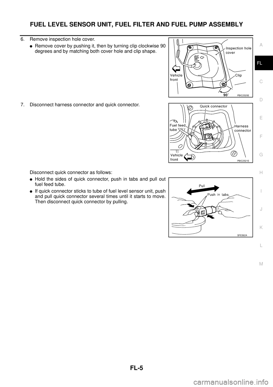
6. Remove inspection hole cover.
�Remove cover by pushing it, then by turning clip clockwise 90
degrees and by matching both cover hole and clip shape.
7. Disconnect harness connector and quick connector.
Disconnect quick connector as follows:
�Hold the sides of quick connector, push in tabs and pull out
fuel feed tube.
�If quick connector sticks to tube of fuel level sensor unit, push
and pull quick connector several times until it starts to move.
Then disconnect quick connector by pulling.
PBIC2520E
PBIC2521E
SFE562A