Page 966 of 3502
![NISSAN TEANA 2003 Service Manual CO-14
[QR]
RADIATOR
6. Remove radiator hoses (upper and lower) and reservoir tank hose.
7. Remove reservoir tank.
8. Remove battery and battery tray, and move fuse and fusible link block to aside. R](/manual-img/5/57392/w960_57392-965.png "NISSAN TEANA 2003 Service Manual CO-14
[QR]
RADIATOR
6. Remove radiator hoses (upper and lower) and reservoir tank hose.
7. Remove reservoir tank.
8. Remove battery and battery tray, and move fuse and fusible link block to aside. R")
CO-14
[QR]
RADIATOR
6. Remove radiator hoses (upper and lower) and reservoir tank hose.
7. Remove reservoir tank.
8. Remove battery and battery tray, and move fuse and fusible link block to aside. Refer to SC-4, "
BAT-
TERY" .
9. Remove mounting brackets to lift up and remove radiator and radiator cooling fan assembly.
CAUTION:
Do not damage or scratch A/C condenser and radiator core when removing.
10. Remove radiator cooling fan assembly from radiator.
INSTALLATION
Installation is the reverse order of removal.
INSPECTION AFTER INSTALLATION
�Check for leaks of engine coolant using radiator cap tester adapter [SST: EG17650301] and a radiator cap
tester (commercial service tool). Refer to CO-10, "
LEAK CHECK" .
�Start and warm up engine. Visually check if there is no leaks of engine coolant and A/T fluid.
Checking Radiator CapBBS005A5
�Check valve seat of radiator cap.
–Check if valve seat is swollen to the extent that the edge of the
plunger cannot be seen when watching it vertically from the top.
–Check if valve seat has no soil and damage.
�Pull negative-pressure valve to open it, and make sure that it is
completely closed when released.
–Make sure that there is no dirt or damage on the valve seat of
radiator cap negative-pressure valve.
–Make sure that there are no unusualness in the opening and
closing conditions of negative-pressure valve.
�Check radiator cap relief pressure.
–When connecting radiator cap to the radiator cap tester (com-
mercial service tool) and the radiator cap tester adapter (SST),
apply engine coolant to the cap seal surface.
�Replace radiator cap if there is an unusualness related to the above three.
PBIC2816E
SMA967B
Standard:
78 - 98 kPa (0.78 - 0.98bar, 0.8 - 1.0 kg/cm
2 , 11 - 14 psi)
Limit:
59 kPa (0.59bar, 0.6 kg/cm
2 , 9 psi)
SLC755AC
Page 967 of 3502
![NISSAN TEANA 2003 Service Manual RADIATOR
CO-15
[QR]
C
D
E
F
G
H
I
J
K
L
MA
CO
CAUTION:
When installing radiator cap, thoroughly wipe out the radiator filler neck to remove any waxy residue
or foreign material.
Checking RadiatorBBS](/manual-img/5/57392/w960_57392-966.png "NISSAN TEANA 2003 Service Manual RADIATOR
CO-15
[QR]
C
D
E
F
G
H
I
J
K
L
MA
CO
CAUTION:
When installing radiator cap, thoroughly wipe out the radiator filler neck to remove any waxy residue
or foreign material.
Checking RadiatorBBS")
RADIATOR
CO-15
[QR]
C
D
E
F
G
H
I
J
K
L
MA
CO
CAUTION:
When installing radiator cap, thoroughly wipe out the radiator filler neck to remove any waxy residue
or foreign material.
Checking RadiatorBBS005A6
Check radiator for mud or clogging. If necessary, clean radiator as follows.
�Be careful not to bend or damage radiator fins.
�When radiator is cleaned without removal, remove all surrounding parts such as cooling fan, radiator
shroud and horns. Then tape harness and connectors to prevent water from entering.
1. Apply water by hose to the back side of the radiator core vertically downward.
2. Apply water again to all radiator core surface once per minute.
3. Stop washing if any stains no longer flow out from radiator.
4. Blow air into the back side of radiator core vertically downward.
�Use compressed air lower than 490 kPa (4.9 bar, 5 kg/cm2 , 71 psi) and keep distance more than 30
cm (11.8 in).
5. Blow air again into all the radiator core surfaces once per minute until no water sprays out.
Page 968 of 3502
CO-16
[QR]
RADIATOR (ALUMINUM TYPE)
RADIATOR (ALUMINUM TYPE)PFP:21460
Disassembly and AssemblyBBS005A7
PREPARATION
1. Attach the spacer to the tip of radiator plate pliers A (SST).
Spacer specification: 18 mm (0.71 in) wide × 8.5 mm (0.335 in)
long × 1.5 mm (0.059 in) thick.
2. Make sure that when radiator plate pliers A [SST: KV99103510] are closed dimension H′′ is approx. 7.6
mm (0.299 in).
3. Adjust dimension H′′ with the spacer thickness, if necessary.
DISASSEMBLY
1. Remove upper and lower tanks with radiator plate pliers B
(SST).
CAUTION:
Do not disassemble lower tank and A/T fluid cooler.
NOTE:
Regard lower tank and A/T fluid cooler as an assembly.
1. Upper tank 2. Sealing rubber 3. Core
4. Lower tank (with A/T fluid cooler)
PBIC2540E
SLC655C
SLC903
Page 969 of 3502
RADIATOR (ALUMINUM TYPE)
CO-17
[QR]
C
D
E
F
G
H
I
J
K
L
MA
CO
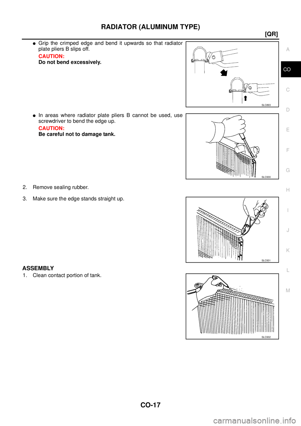
�Grip the crimped edge and bend it upwards so that radiator
plate pliers B slips off.
CAUTION:
Do not bend excessively.
�In areas where radiator plate pliers B cannot be used, use
screwdriver to bend the edge up.
CAUTION:
Be careful not to damage tank.
2. Remove sealing rubber.
3. Make sure the edge stands straight up.
ASSEMBLY
1. Clean contact portion of tank.
SLC893
SLC930
SLC931
SLC932
Page 970 of 3502
CO-18
[QR]
RADIATOR (ALUMINUM TYPE)
2. Install sealing rubber while pushing it in with fingers.
CAUTION:
Be careful not to twist sealing rubber.
3. Caulk tank in numerical order as shown in the figure with radia-
tor plate pliers A (SST).
�Use pliers in the locations where radiator plate pliers A cannot
be used.
SLC917A
SLC904
PBIC2076E
SLC897
Page 971 of 3502
RADIATOR (ALUMINUM TYPE)
CO-19
[QR]
C
D
E
F
G
H
I
J
K
L
MA
CO
4. Make sure that the rim is completely crimped down.
5. Make sure that there is no leakage. Refer to CO-19, "
INSPECTION" .
INSPECTION
1. Apply pressure with radiator cap tester adapter (SST) and radia-
tor cap tester (commercial service tool).
WARNING:
To prevent the risk of hose coming undone while under
pressure, securely fasten it down with hose clamp.
CAUTION:
Attach hose to A/T fluid cooler to seal its inlet and outlet.
2. Check for leakage by soaking radiator in water container with
the testing pressure applied.Standard height “H” : 8.0 - 8.4 mm (0.315 - 0.331 in)
SLC554A
Testing pressure
: 157 kPa (1.57 bar, 1.6 kg/cm
2 , 23 psi)
SLC933
SLC934
Page 972 of 3502
![NISSAN TEANA 2003 Service Manual CO-20
[QR]
COOLING FAN
COOLING FANPFP:21140
Removal and InstallationBBS005A8
REMOVAL
1. Drain engine coolant from radiator. Refer to CO-10, "Changing Engine Coolant" .
CAUTION:
�Perform this step w](/manual-img/5/57392/w960_57392-971.png "NISSAN TEANA 2003 Service Manual CO-20
[QR]
COOLING FAN
COOLING FANPFP:21140
Removal and InstallationBBS005A8
REMOVAL
1. Drain engine coolant from radiator. Refer to CO-10, \"Changing Engine Coolant\" .
CAUTION:
�Perform this step w")
CO-20
[QR]
COOLING FAN
COOLING FANPFP:21140
Removal and InstallationBBS005A8
REMOVAL
1. Drain engine coolant from radiator. Refer to CO-10, "Changing Engine Coolant" .
CAUTION:
�Perform this step when engine is cold.
�Do not spill engine coolant on drive belt.
2. Remove air duct (inlet). Refer to EM-17, "
AIR CLEANER AND AIR DUCT" .
3. Disconnect radiator hose (upper) at radiator side. Refer to CO-13, "
RADIATOR" .
4. Disconnect harness connector from fan motors, and move harness to aside.
5. Remove battery and battery tray, and move fuse and fusible link block to aside. Refer to SC-4, "
BAT-
TERY" .
6. Remove mounting bolts to lift up and remove radiator cooling fan assembly.
CAUTION:
Be careful not to damage or scratch on radiator core.
INSTALLATION
Installation is the reverse order of removal.
INSPECTION AFTER INSTALLATION
Make sure that fan motors operate normally.
NOTE:
Cooling fans are controlled by ECM. For details, refer to EC-218, "
DTC P1217 ENGINE OVER TEMPERA-
TURE" .
1. Cooling fan (RH) 2. Cooling fan (LH) 3. Fan shroud
4. Fan motor
PBIC2514E
Page 974 of 3502
![NISSAN TEANA 2003 Service Manual CO-22
[QR]
WATER PUMP
WATE R P U M PPFP:21020
Removal and InstallationBBS005AA
REMOVAL
1. Drain engine coolant from radiator drain plug at the bottom of radiator and from water drain plug on engine](/manual-img/5/57392/w960_57392-973.png "NISSAN TEANA 2003 Service Manual CO-22
[QR]
WATER PUMP
WATE R P U M PPFP:21020
Removal and InstallationBBS005AA
REMOVAL
1. Drain engine coolant from radiator drain plug at the bottom of radiator and from water drain plug on engine")
CO-22
[QR]
WATER PUMP
WATE R P U M PPFP:21020
Removal and InstallationBBS005AA
REMOVAL
1. Drain engine coolant from radiator drain plug at the bottom of radiator and from water drain plug on engine
cylinder block. Refer to CO-10, "
Changing Engine Coolant" and EM-81, "CYLINDER BLOCK" .
CAUTION:
�Perform this step when engine is cold.
�Do not spill engine coolant on drive belt.
2. Remove the following parts.
�Undercover and splash guard (RH)
�Drive belt; Refer to EM-14, "DRIVE BELTS" .
�Drive belt auto-tensioner; Refer to EM-15, "Removal and Installation of Drive Belt Auto-Tensioner" .
3. Remove water pump.
�Engine coolant will leak from cylinder block, so have a receptacle ready below.
CAUTION:
�Handle water pump vane so that it does not contact any other parts.
�Water pump cannot be disassembled and should be replaced as a unit.
4. Remove water pump housing with the following procedure;
a. Remove alternator. Refer to SC-27, "
CHARGING SYSTEM" .
b. Remove oil level gauge and oil level gauge guide. Refer to EM-26, "
OIL PAN AND OIL STRAINER" .
CAUTION:
Plug the oil level gauge guide opening to prevent oil pan from entering foreign materials.
c. Remove mounting bolts for water pipe.
d. Remove water pump housing.
5. Remove exhaust manifold and three way catalyst assembly. Refer to EM-23, "
EXHAUST MANIFOLD
AND THREE WAY CATALYST" .
6. Remove water pipe.
PBIC2253E
1. Water pump 2. Gasket 3. Gasket
4. Water pump housing 5. Gasket 6. Water pipe
7. O-ring
![NISSAN TEANA 2003 Service Manual CO-16
[QR]
RADIATOR (ALUMINUM TYPE)
RADIATOR (ALUMINUM TYPE)PFP:21460
Disassembly and AssemblyBBS005A7
PREPARATION
1. Attach the spacer to the tip of radiator plate pliers A (SST).
Spacer specificat](/manual-img/5/57392/w960_57392-967.png "NISSAN TEANA 2003 Service Manual CO-16
[QR]
RADIATOR (ALUMINUM TYPE)
RADIATOR (ALUMINUM TYPE)PFP:21460
Disassembly and AssemblyBBS005A7
PREPARATION
1. Attach the spacer to the tip of radiator plate pliers A (SST).
Spacer specificat")
![NISSAN TEANA 2003 Service Manual CO-18
[QR]
RADIATOR (ALUMINUM TYPE)
2. Install sealing rubber while pushing it in with fingers.
CAUTION:
Be careful not to twist sealing rubber.
3. Caulk tank in numerical order as shown in the figu](/manual-img/5/57392/w960_57392-969.png "NISSAN TEANA 2003 Service Manual CO-18
[QR]
RADIATOR (ALUMINUM TYPE)
2. Install sealing rubber while pushing it in with fingers.
CAUTION:
Be careful not to twist sealing rubber.
3. Caulk tank in numerical order as shown in the figu")
![NISSAN TEANA 2003 Service Manual RADIATOR (ALUMINUM TYPE)
CO-19
[QR]
C
D
E
F
G
H
I
J
K
L
MA
CO
4. Make sure that the rim is completely crimped down.
5. Make sure that there is no leakage. Refer to CO-19, "
INSPECTION" .
INSPECTION](/manual-img/5/57392/w960_57392-970.png "NISSAN TEANA 2003 Service Manual RADIATOR (ALUMINUM TYPE)
CO-19
[QR]
C
D
E
F
G
H
I
J
K
L
MA
CO
4. Make sure that the rim is completely crimped down.
5. Make sure that there is no leakage. Refer to CO-19, \"
INSPECTION\" .
INSPECTION")