Page 3313 of 3502

AUTOMATIC DRIVE POSITIONER
SE-57
C
D
E
F
G
H
J
K
L
MA
B
SE
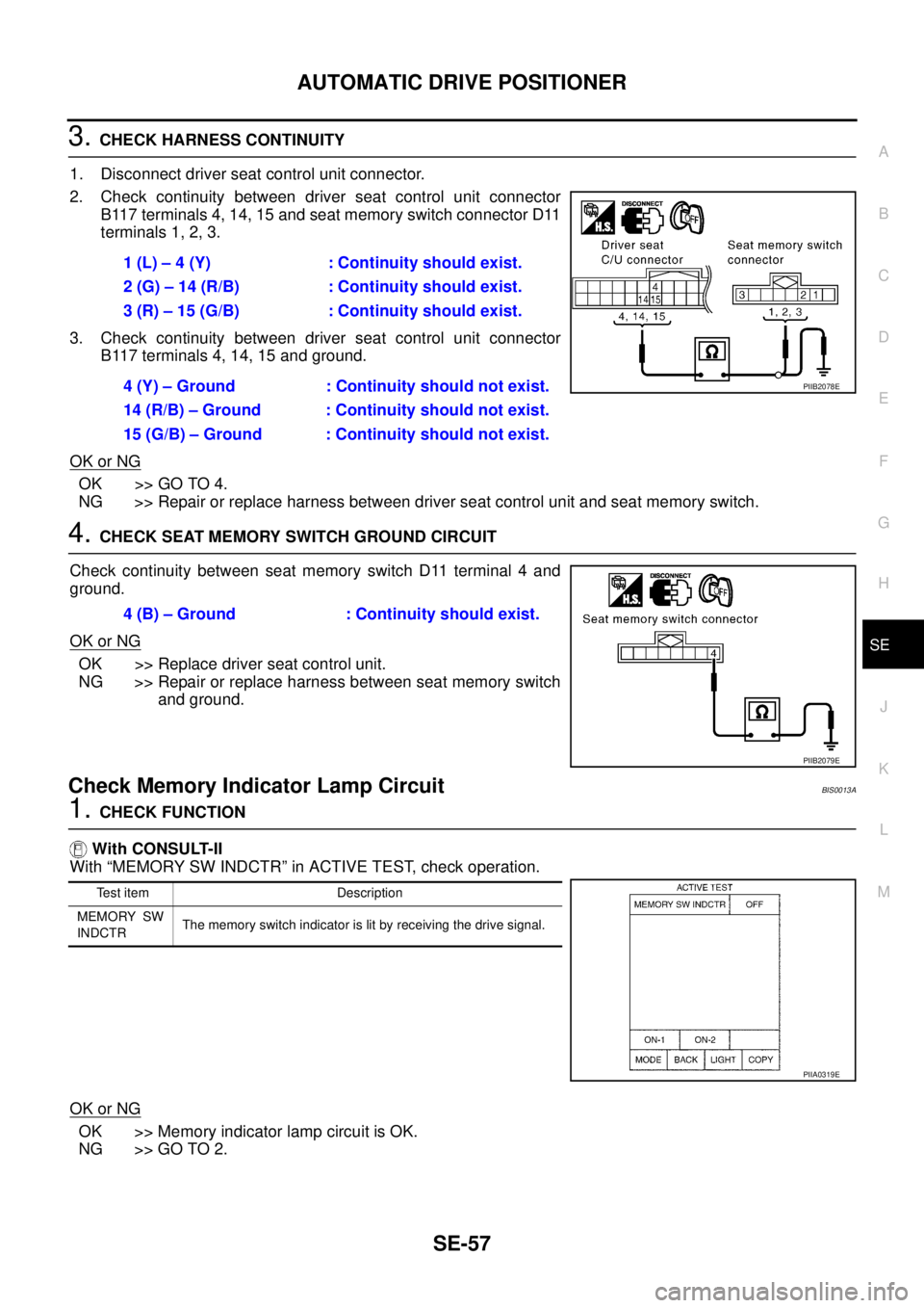
3. CHECK HARNESS CONTINUITY
1. Disconnect driver seat control unit connector.
2. Check continuity between driver seat control unit connector
B117 terminals 4, 14, 15 and seat memory switch connector D11
terminals 1, 2, 3.
3. Check continuity between driver seat control unit connector
B117 terminals 4, 14, 15 and ground.
OK or NG
OK >> GO TO 4.
NG >> Repair or replace harness between driver seat control unit and seat memory switch.
4. CHECK SEAT MEMORY SWITCH GROUND CIRCUIT
Check continuity between seat memory switch D11 terminal 4 and
ground.
OK or NG
OK >> Replace driver seat control unit.
NG >> Repair or replace harness between seat memory switch
and ground.
Check Memory Indicator Lamp Circuit BIS0013A
1. CHECK FUNCTION
With CONSULT-II
With “MEMORY SW INDCTR” in ACTIVE TEST, check operation.
OK or NG
OK >> Memory indicator lamp circuit is OK.
NG >> GO TO 2.1 (L) – 4 (Y) : Continuity should exist.
2 (G) – 14 (R/B) : Continuity should exist.
3 (R) – 15 (G/B) : Continuity should exist.
4 (Y) – Ground : Continuity should not exist.
14 (R/B) – Ground : Continuity should not exist.
15 (G/B) – Ground : Continuity should not exist.
PIIB2078E
4 (B) – Ground : Continuity should exist.
PIIB2079E
Test item Description
MEMORY SW
INDCTRThe memory switch indicator is lit by receiving the drive signal.
PIIA0319E
Page 3314 of 3502

SE-58
AUTOMATIC DRIVE POSITIONER
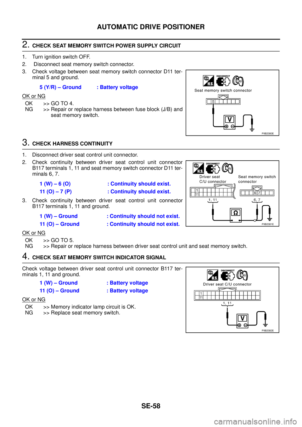
2. CHECK SEAT MEMORY SWITCH POWER SUPPLY CIRCUIT
1. Turn ignition switch OFF.
2. Disconnect seat memory switch connector.
3. Check voltage between seat memory switch connector D11 ter-
minal 5 and ground.
OK or NG
OK >> GO TO 4.
NG >> Repair or replace harness between fuse block (J/B) and
seat memory switch.
3. CHECK HARNESS CONTINUITY
1. Disconnect driver seat control unit connector.
2. Check continuity between driver seat control unit connector
B117 terminals 1, 11 and seat memory switch connector D11 ter-
minals 6, 7.
3. Check continuity between driver seat control unit connector
B117 terminals 1, 11 and ground.
OK or NG
OK >> GO TO 5.
NG >> Repair or replace harness between driver seat control unit and seat memory switch.
4. CHECK SEAT MEMORY SWITCH INDICATOR SIGNAL
Check voltage between driver seat control unit connector B117 ter-
minals 1, 11 and ground.
OK or NG
OK >> Memory indicator lamp circuit is OK.
NG >> Replace seat memory switch.5 (Y/R) – Ground : Battery voltage
PIIB2080E
1 (W) – 6 (O) : Continuity should exist.
11 (O) – 7 (P) : Continuity should exist.
1 (W) – Ground : Continuity should not exist.
11 (O) – Ground : Continuity should not exist.
PIIB2081E
1 (W) – Ground : Battery voltage
11 (O) – Ground : Battery voltage
PIIB2082E
Page 3356 of 3502
SE-100
FRONT SEAT
1. Screw cap 2. Screw 3. Seatback garnish
4. Headrest 5. Headrest holder (locked) 6. Headrest holder (free)
7. Side air bag module 8. Seatback frame 9. Nut
10. Seat cushion frame 11. Bolt 12. Seatback pad
13. Seat heater unit 14. Seatback trim 15. Seat cushion pad
16. Seat cushion trim 17. Anchor bolt 18. Seat belt buckle
19. Seat harness assembly 20. Seat adjusting assembly 21. Seat sliding outer cover
22. Bolt 23. Seat slide & lifter switch knob 24. Seat switch assembly
25. Seat switch escutcheon 26. Seat reclining switch knob 27. Seat cushion outer finisher
28. Bracket 29. Memory control unit 30. Bolt
Page 3365 of 3502
FRONT SEAT
SE-109
C
D
E
F
G
H
J
K
L
MA
B
SE
4. Remove retainer from seat cushion lower.
5. Disconnect seat heater harness connector (only with the seat heater).
6. Remove seat cushion trim and pad from seat cushion frame.
7. After removing seat cushion trim and pad, remove hog rings (non-reusable parts) to separate trim and pad
and seat heater unit.
8. Remove screws, and then remove the power seat switch.
9. Remove seat cushion bolts, and then remove seat cushion
frame.
10. Disconnect seat position memory unit connector (only with the position memory seat).
11. Remove seat position memory unit bolts, and then, remove seat
position memory unit (only with position memory seat).
ASSEMBLY
Assemble in the reverse order of disassembly.
Disassembly and Assembly of Seat Cushion (Massage and Power Ottoman
Seat)
BIS0014J
DISASSEMBLY
1. Remove seat cushion outer finisher.
PIIA6314E
PIIB1948E
PIIB1949E
Page:
< prev 1-8 9-16 17-24