Page 814 of 3502

Diagnostic Procedure 4BIS000YQ
Self-diagnostic results:
“LOCK MODE” displayed on CONSULT-II screen
1. CHECK SELF-DIAGNOSTIC RESULTS
Check SELF-DIAGNOSTIC RE")
BL-156
NATS(NISSAN ANTI-THEFT SYSTEM)
Diagnostic Procedure 4BIS000YQ
Self-diagnostic results:
“LOCK MODE” displayed on CONSULT-II screen
1. CHECK SELF-DIAGNOSTIC RESULTS
Check SELF-DIAGNOSTIC RESULTS “LOCK MODE” is displayed
on CONSULT-II screen.
Is CONSULT-II screen displayed as above?
Yes >> GO TO 2.
No >> GO TO BL-152, "
Trouble Diagnosis Symptom Chart" .
2. ESCAPE FROM LOCK MODE
1. Turn ignition switch OFF.
2. Turn ignition switch ON with registered key. (Do not start engine.) Wait 5 seconds.
3. Return the key to OFF position. Wait 5 seconds.
4. Repeat steps 2 and 3 twice (total of three cycles).
5. Start the engine.
Does engine start?
Yes >> System is OK (Now system is escaped from “LOCK MODE”).
No >> GO TO 3.
3. PERFORM INITIALIZATION WITH CONSULT-II
Perform initialization with CONSULT-II.
For initialization, refer to “CONSULT-II Operation Manual NATS”.
NOTE:
If the initialization is not completed or malfunctions, CONSULT-II
shows the message on the screen.
Can the system be initialized?
Ye s > > S y s t e m i s O K .
No >> GO TO 4
PIIA1264E
SEL297W
Page 815 of 3502

BL-157
C
D
E
F
G
H
J
K
L
MA
B
BL
4. PERFORM INITIALIZATION WITH CONSULT-II AGAIN
1. Replace BCM.
2. Perform initialization with CONSULT-II.
For initialization, refer t")
NATS(NISSAN ANTI-THEFT SYSTEM)
BL-157
C
D
E
F
G
H
J
K
L
MA
B
BL
4. PERFORM INITIALIZATION WITH CONSULT-II AGAIN
1. Replace BCM.
2. Perform initialization with CONSULT-II.
For initialization, refer to “CONSULT-II Operation Manual
NATS”.
NOTE:
If the initialization is not completed or malfunctions, CONSULT-II
shows the message on the screen.
Can the system be initialized?
Yes >> System is OK. BCM is malfunctioning.
No >> ECM is malfunctioning.
�Replace ECM.
�Perform initialization or re-communicating function.
–For initialization, refer to “CONSULT-II Operation
Manual NATS”.
–For re-communicating function, refer to BL-142, "ECM Re-Communicating Function" .
Diagnostic Procedure 5BIS000YR
Self-diagnostic results:
“CHAIN OF IMMU-KEY” displayed on CONSULT-II screen
1. CHECK SELF-DIAGNOSTIC RESULTS
Check self-diagnostic results “CHAIN OF IMMU-KEY” displayed on CONSULT-II screen.
Is CONSULT-II screen displayed as above?
Ye s > > G O T O 2 .
No >> GO TO BL-152, "
Trouble Diagnosis Symptom Chart" .
2. CHECK NATS ANTENNA AMP. INSTALLATION
Check NATS antenna amp. installation. Refer to BL-160, "
Removal and Installation NATS Antenna Amp." .
OK or NG
OK >> GO TO 3.
NG >> Reinstall NATS antenna amp. correctly.
3. CHECK KEY ID CHIP
Start engine with another registered ignition key or mechanical key.
Does the engine start?
Yes >> Ignition key or mechanical key ID chip is malfunctioning.
�Replace the ignition key or mechanical key.
�Perform initialization with CONSULT-II.
For initialization, refer to “CONSULT-II Operation Manual NATS–IVIS/NVIS”.
No >> GO TO 4.
SEL297W
Page 817 of 3502

BL-159
C
D
E
F
G
H
J
K
L
MA
B
BL
7. CHECK NATS ANTENNA AMP. GROUND LINE CIRCUIT
1. Turn ignition switch OFF.
2. Check continuity between NATS antenna amp. connector M2")
NATS(NISSAN ANTI-THEFT SYSTEM)
BL-159
C
D
E
F
G
H
J
K
L
MA
B
BL
7. CHECK NATS ANTENNA AMP. GROUND LINE CIRCUIT
1. Turn ignition switch OFF.
2. Check continuity between NATS antenna amp. connector M22 terminal 3 (B) and ground.
OK or NG
OK >> NATS antenna amp. is malfunctioning.
NG >>
�Repair or replace the harness between NATS
antenna amp. and ground.
Diagnostic Procedure 6BIS000YS
“SECURITY INDICATOR LAMP DOES NOT LIGHT UP”
1. CHECK FUSE
Check 10A fuse [No.19, located in the fuse block (J/B)]
OK or NG
OK >> GO TO 2.
NG >> Replace fuse.
2. CHECK SECURITY INDICATOR LAMP
1. Install 10A fuse.
2. Start engine and then turn ignition switch OFF.
3. Check the security indicator lamp lights up.
OK or NG
OK >> INSPECTION END
NG >> GO TO 3.
3. CHECK SECURITY INDICATOR LAMP POWER SUPPLY CIRCUIT
1. Disconnect security indicator lamp connector.
2. Check voltage between security indicator lamp connector M19
terminal 1 (Y/R) and ground.
OK or NG
OK >> GO TO 4.
NG >> Check harness for open or short between fuse and
security indicator lamp. 3 (B) – Ground : Continuity should exist.
PIIA6148E
Security indicator lamp should light up.
1 (Y/R) – Ground : Battery voltage
PIIA6149E
Page 824 of 3502

BR-6
BRAKE PEDAL
BRAKE PEDALPFP:46501
Inspection and AdjustmentBFS000BG
Play and clearance inspection between brake pedal and floor panel with pedal depressed.
�Check brake pedal height from dash lower panel (1).
�Adjust height referring to the following specifications.
ADJUSTMENT
1. Loosen stop lamp switch, brake switch and/or ASCD cancel
switch by turning it counterclockwise by 45°.
2. Loosen lock nut “A” on input rod, then rotate input rod to set,
brake pedal to the specified height, and tighten lock nut “A”.
Refer to BR-22, "
COMPONENTS" .
CAUTION:
Make sure the threaded end of input rod stays inside clevis.
3. With pedal pulled and held by hand, press stop lamp switch,
brake switch and/or ASCD cancel switch until its threaded end
contacts bracket.
4. With threaded end of stop lamp switch, brake switch and/or
ASCD cancel switch contacting bracket, rotate switch clockwise
by 45° to secure.
CAUTION:
�Make sure that the clearance “C” between bracket and
end of stop lamp switch, brake switch and/or ASCD can-
cel switch is within the standard.
�When locking stop lamp switch and ASCD cancel switch,
pull brake pedal to avoid moving toward the direction
where switches are being pressed.
5. Check the pedal play.
CAUTION:
Make sure that stop lamps goes off when pedal is released.
6. Start engine to check brake pedal depressed height.
H1Brake pedal free height (from dash lower panel
(1) top surface)195.8 - 205.8 mm
(7.71 - 8.10 in)
H
2
Depressed brake pedal height
[under a force of 490 N (50 kg, 110 lb) with
engine running]More than 115 mm
(4.53 in)
CClearance between the threaded end of stop
lamp switch, brake switch and/or ASCD cancel
switch (2) and bracket (3)0.74 - 1.96 mm
(0.0291 - 0.0772 in)
A Pedal play3-11 mm
(0.12 - 0.43 in)
SFIA2743J
PFIA0824E
Page 831 of 3502
BRAKE TUBE AND HOSE
BR-13
C
D
E
G
H
I
J
K
L
MA
B
BR
Inspection After InstallationBFS000BO
CAUTION:
If leakage occurs around brake tube and hose connections, retighten or, if damaged part is detected,
replace the damage part.
1. Check brake hoses, brake tubes, and connections for fluid leakage, damage, twists, deformation, contact
with other parts, and loose connections.
2. While depressing brake pedal under a force of 785 N (80 kg, 177 lb) with engine running for approximately
5 seconds, check for fluid leak each part.
Page 839 of 3502

BRAKE BOOSTER
BR-21
C
D
E
G
H
I
J
K
L
MA
B
BR
BRAKE BOOSTERPFP:47200
On-Board Inspection and ServiceBFS000BS
OPERATION CHECK
With engine stopped, change the vacuum to the atmospheric pres-
sure by depressing brake pedal several times. Then with brake
pedal fully depressed, start engine and when the vacuum pressure
reaches the standard, make sure that clearance between brake
pedal and floor panel decreases.
CAUTION:
Depressing pedal interval is approximately 5 seconds.
AIR TIGHT CHECK
�Run engine at idle for approximately 1 minute, and stop it after
applying vacuum to booster. Depress brake pedal normally to
change the vacuum to the atmospheric pressure. Make sure
distance between brake pedal and floor panel gradually
increases.
�Depress brake pedal while engine is running, and stop engine
with brake pedal is depressed. Brake pedal stroke should not
change after holding brake pedal down for 30 seconds.
CAUTION:
Depressing brake pedal interval is approximately at intervals 5
seconds.
BRA0037D
SBR365AA
Page 840 of 3502

BR-22
BRAKE BOOSTER
Removal and InstallationBFS000BT
COMPONENTS
CAUTION:
�Be careful not to splash brake fluid on painted areas; it may cause paint damage. If brake fluid is
splashed on painted surfaces of body, immediately wipe it off and them wash it away with water
immediately.
�Be careful not to deform or bend brake tube while removing and installing brake booster.
�Replace clevis pin if it is damaged.
�Be careful not to damage brake booster stud bolt threads. If brake booster is tilted or inclined dur-
ing installation, dash panel may damage the threads.
�Install check valve in the correct direction.
REMOVAL
1. Remove vacuum hose from brake booster. Refer to BR-24, "VACUUM LINES" .
2. Remove brake master cylinder. Refer to BR-14, "
Removal and Installation" .
3. Remove snap pin and clevis pin from brake pedal.
4. Remove nuts on brake booster and brake pedal assembly.
5. Remove brake booster from dash panel in engine room side.
1. Reservoir tank 2. Master cylinder 3. Brake booster
4. Gasket 5. Lock nut
SFIA2633E
SFIA2044E
Page 842 of 3502
BR-24
VACUUM LINES
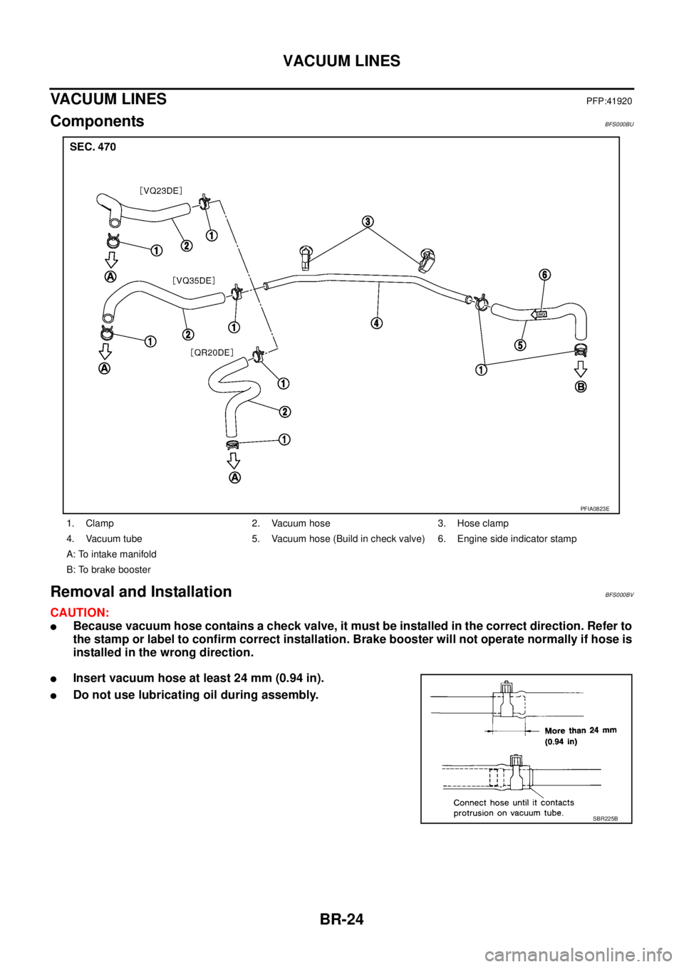
VACUUM LINESPFP:41920
ComponentsBFS000BU
Removal and InstallationBFS000BV
CAUTION:
�Because vacuum hose contains a check valve, it must be installed in the correct direction. Refer to
the stamp or label to confirm correct installation. Brake booster will not operate normally if hose is
installed in the wrong direction.
�Insert vacuum hose at least 24 mm (0.94 in).
�Do not use lubricating oil during assembly.
1. Clamp 2. Vacuum hose 3. Hose clamp
4. Vacuum tube 5. Vacuum hose (Build in check valve) 6. Engine side indicator stamp
A: To intake manifold
B: To brake booster
PFIA0823E
SBR225B