Page 22 of 3502

AT-14
A/T FLUID
A/T FLUIDPFP:KLE40
Checking A/T FluidBCS000ZL
1. Warm up engine.
2. Check for A/T fluid leakage.
3. Before driving, A/T fluid level can be checked A/T at fluid tem-
peratures of 30 to 50°C (86 to 122°F) using “COLD” range on A/
T fluid level gauge.
a. Park vehicle on level surface and set parking brake.
b. Start engine and move selector lever through each gear posi-
tion. Leave selector lever in “P” position.
c. Check A/T fluid level with engine idling.
d. Remove A/T fluid level gauge and wipe clean with lint-free
paper.
CAUTION:
When wiping away the A/T fluid level gauge, always use
lint-free paper, not a cloth one.
e. Re-insert A/T fluid level gauge into A/T fluid charging pipe as far
as it will go.
CAUTION:
Firmly fix the A/T fluid level gauge to the A/T fluid charging
pipe using a stopper attached.
f. Remove A/T fluid level gauge and note reading. If reading is at
low side of range, add ATF to the A/T fluid charging pipe.
CAUTION:
Do not overfill.
4. Drive vehicle for approximately 5 minutes in urban areas.
5. Recheck A/T fluid level at A/T fluid temperatures of 50 to 80°C (122 to 176°F) using “HOT” range on A/T
fluid level gauge.
CAUTION:
�When wiping away the A/T fluid level gauge, always use lint-free paper, not cloth one.
�Firmly fix the A/T fluid level gauge to the A/T fluid charging pipe using a stopper attached.
SMA146B
SCIA3451E
SMA051D
Page 23 of 3502

A/T FLUID
AT-15
D
E
F
G
H
I
J
K
L
MA
B
AT
6. Check A/T fluid condition.
�If ATF is very dark or smells burned, checking operation of A/
T. Flush cooling system after repair of A/T.
�If ATF contains frictional material (clutches, bands, etc.),
replace radiator and flush cooler line using cleaning solvent
and compressed air after repair of A/T. Refer to CO-37,
"RADIATOR" , CO-40, "RADIATOR (ALUMINUM TYPE)" .
7. Install the removed A/T fluid level gauge in the A/T fluid charging
pipe.
CAUTION:
Firmly fix the A/T fluid level gauge to the A/T fluid charging
pipe using a stopper attached.
Changing A/T FluidBCS000ZM
1. Warm up ATF.
2. Stop engine.
3. Drain ATF from drain plug and refill with new ATF. Always refill same volume with drained ATF.
CAUTION:
Do not reuse drain plug gasket.
4. Run engine at idle speed for 5 minutes.
5. Check A/T fluid level and condition. Refer to AT- 1 4 , "
Checking A/T Fluid" . If ATF is still dirty, repeat steps
2 through 5.
SAT638A
Fluid grade:
Genuine NISSAN ATF Matic Fluid D or equivalent.
Refer to MA-14, "
RECOMMENDED FLUIDS AND LUBRICANTS"
.
Fluid capacity
For QR20DE engine models
: Approx. 8.4 (7-3/8 lmp qt)
For VQ23DE engine models
: Approx. 8.9 (7-7/8 lmp qt)
Drain plug:
: 34 N·m (3.5 kg-m, 25 ft-lb)
Page 25 of 3502

A/T CONTROL SYSTEM
AT-17
D
E
F
G
H
I
J
K
L
MA
B
AT
Shift MechanismBCS000ZO
CONSTRUCTION
FUNCTION OF CLUTCH AND BRAKE
1. Torque converter 2. Oil pump 3. Input shaft
4. Brake band 5. Reverse clutch 6. High clutch
7. Front sun gear 8. Front pinion gear 9. Front internal gear
10. Front planetary carrier 11. Rear sun gear 12. Rear pinion gear
13. Rear internal gear 14. Rear planetary carrier 15. Forward clutch
16. Forward one-way clutch 17. Overrun clutch 18. Low one-way clutch
19. Low & reverse brake 20. Parking pawl 21. Parking gear
22. Output shaft 23. Idler gear 24. Output gear
SAT998I
Clutch and brake components Abbr. Function
5Reverse clutch R/C To transmit input power to front sun gear 7 .
6High clutch H/C To transmit input power to front planetary carrier 10 .
15Forward clutch F/C To connect front planetary carrier 10 with forward one-way clutch 16 .
17Overrun clutch O/C To connect front planetary carrier 10 with rear internal gear 13 .
4Brake band B/B To lock front sun gear 7 .
16Forward one-way clutch F/O.CWhen forward clutch 15 is engaged, to stop rear internal gear 13 from rotating
in opposite direction against engine revolution.
18Low one-way clutch L/O.CTo stop front planetary carrier 10 from rotating in opposite direction against
engine revolution.
19Low & reverse brake L & R/B To lock front planetary carrier 10 .
Page 26 of 3502

AT-18
A/T CONTROL SYSTEM
CLUTCH AND BAND CHART
�*1: Oil pressure is applied to both 2nd “apply” side and 3rd “release” side of band servo piston. However, brake band does not con-
tract because oil pressure area on the “release” side is greater than that on the “apply” side.
�*2: Oil pressure is applied to 4th “apply” side in condition *1 above, and brake band contracts.
�: Operates.
�A: Operates when throttle opening is less than 3/16, activating engine brake.
�B: Operates during “progressive” acceleration.
�C: Operates but does not affect power transmission.
�D: Operates when throttle opening is less than 3/16, but does not affect engine brake. Shift posi-
tionR/C
5H/C
6F/C
15O/C
17Band servo
F/O.C
16L/O.C
18L&R/B
19Lock-
upRemarks
2nd
apply3rd
release4th
apply
PPA R K
POSITION
RREVERSE
POSITION
NNEUTRAL
POSITION
1st D B B
D2nd A BAutomatic
shift
3rd A *1C C B1 ⇔ 2 ⇔ 3
⇔ 4
4th C *2C C
31st D B B
Automatic
shift
1 ⇔ 2 ⇔ 3 2nd A B
3rd A *1C C B
21stBB
Automatic
shift
1 ⇔ 2 ⇐ 3 2ndB
3rd *1C C B
11stBB
Locks (held
stationary)
in 1st speed
1 ⇐ 2 ⇐ 3 2ndB
3rd *1C C B
Page 28 of 3502
AT-20
A/T CONTROL SYSTEM
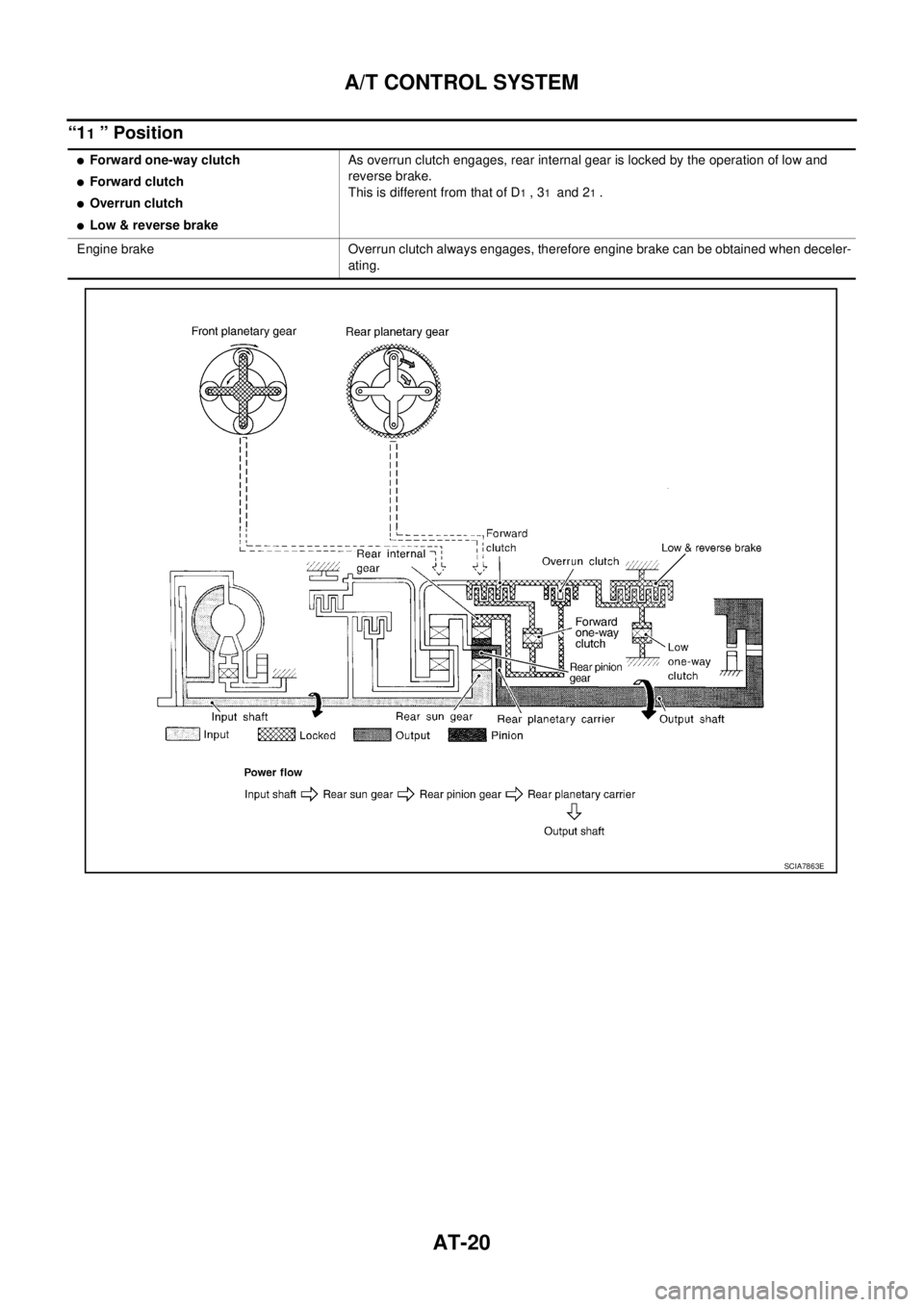
“11 ” Position
�Forward one-way clutch
�Forward clutch
�Overrun clutch
�Low & reverse brakeAs overrun clutch engages, rear internal gear is locked by the operation of low and
reverse brake.
This is different from that of D
1 , 31 and 21 .
Engine brake Overrun clutch always engages, therefore engine brake can be obtained when deceler-
ating.
SCIA7863E
Page 29 of 3502
A/T CONTROL SYSTEM
AT-21
D
E
F
G
H
I
J
K
L
MA
B
AT
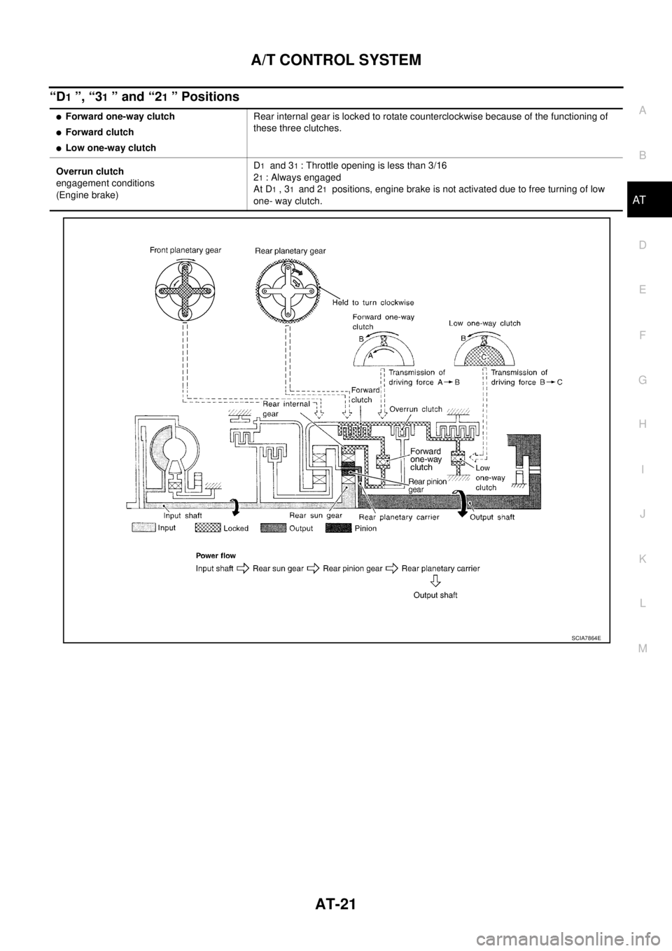
“D1 ”, “31 ” and “21 ” Positions
�Forward one-way clutch
�Forward clutch
�Low one-way clutchRear internal gear is locked to rotate counterclockwise because of the functioning of
these three clutches.
Overrun clutch
engagement conditions
(Engine brake)D
1 and 31 : Throttle opening is less than 3/16
2
1 : Always engaged
At D
1 , 31 and 21 positions, engine brake is not activated due to free turning of low
one- way clutch.
SCIA7864E
Page 32 of 3502
AT-24
A/T CONTROL SYSTEM
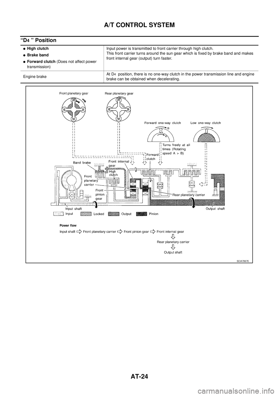
“D4 ” Position
�High clutch
�Brake band
�Forward clutch (Does not affect power
transmission)Input power is transmitted to front carrier through high clutch.
This front carrier turns around the sun gear which is fixed by brake band and makes
front internal gear (output) turn faster.
Engine brakeAt D
4 position, there is no one-way clutch in the power transmission line and engine
brake can be obtained when decelerating.
SCIA7867E
Page 33 of 3502
A/T CONTROL SYSTEM
AT-25
D
E
F
G
H
I
J
K
L
MA
B
AT
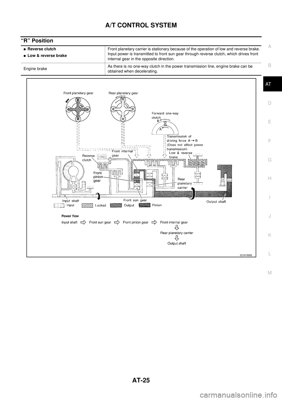
“R” Position
�Reverse clutch
�Low & reverse brakeFront planetary carrier is stationary because of the operation of low and reverse brake.
Input power is transmitted to front sun gear through reverse clutch, which drives front
internal gear in the opposite direction.
Engine brakeAs there is no one-way clutch in the power transmission line, engine brake can be
obtained when decelerating.
SCIA7868E