Page 966 of 3502
![NISSAN TEANA 2003 Service Manual CO-14
[QR]
RADIATOR
6. Remove radiator hoses (upper and lower) and reservoir tank hose.
7. Remove reservoir tank.
8. Remove battery and battery tray, and move fuse and fusible link block to aside. R](/manual-img/5/57392/w960_57392-965.png "NISSAN TEANA 2003 Service Manual CO-14
[QR]
RADIATOR
6. Remove radiator hoses (upper and lower) and reservoir tank hose.
7. Remove reservoir tank.
8. Remove battery and battery tray, and move fuse and fusible link block to aside. R")
CO-14
[QR]
RADIATOR
6. Remove radiator hoses (upper and lower) and reservoir tank hose.
7. Remove reservoir tank.
8. Remove battery and battery tray, and move fuse and fusible link block to aside. Refer to SC-4, "
BAT-
TERY" .
9. Remove mounting brackets to lift up and remove radiator and radiator cooling fan assembly.
CAUTION:
Do not damage or scratch A/C condenser and radiator core when removing.
10. Remove radiator cooling fan assembly from radiator.
INSTALLATION
Installation is the reverse order of removal.
INSPECTION AFTER INSTALLATION
�Check for leaks of engine coolant using radiator cap tester adapter [SST: EG17650301] and a radiator cap
tester (commercial service tool). Refer to CO-10, "
LEAK CHECK" .
�Start and warm up engine. Visually check if there is no leaks of engine coolant and A/T fluid.
Checking Radiator CapBBS005A5
�Check valve seat of radiator cap.
–Check if valve seat is swollen to the extent that the edge of the
plunger cannot be seen when watching it vertically from the top.
–Check if valve seat has no soil and damage.
�Pull negative-pressure valve to open it, and make sure that it is
completely closed when released.
–Make sure that there is no dirt or damage on the valve seat of
radiator cap negative-pressure valve.
–Make sure that there are no unusualness in the opening and
closing conditions of negative-pressure valve.
�Check radiator cap relief pressure.
–When connecting radiator cap to the radiator cap tester (com-
mercial service tool) and the radiator cap tester adapter (SST),
apply engine coolant to the cap seal surface.
�Replace radiator cap if there is an unusualness related to the above three.
PBIC2816E
SMA967B
Standard:
78 - 98 kPa (0.78 - 0.98bar, 0.8 - 1.0 kg/cm
2 , 11 - 14 psi)
Limit:
59 kPa (0.59bar, 0.6 kg/cm
2 , 9 psi)
SLC755AC
Page 971 of 3502
RADIATOR (ALUMINUM TYPE)
CO-19
[QR]
C
D
E
F
G
H
I
J
K
L
MA
CO
4. Make sure that the rim is completely crimped down.
5. Make sure that there is no leakage. Refer to CO-19, "
INSPECTION" .
INSPECTION
1. Apply pressure with radiator cap tester adapter (SST) and radia-
tor cap tester (commercial service tool).
WARNING:
To prevent the risk of hose coming undone while under
pressure, securely fasten it down with hose clamp.
CAUTION:
Attach hose to A/T fluid cooler to seal its inlet and outlet.
2. Check for leakage by soaking radiator in water container with
the testing pressure applied.Standard height “H” : 8.0 - 8.4 mm (0.315 - 0.331 in)
SLC554A
Testing pressure
: 157 kPa (1.57 bar, 1.6 kg/cm
2 , 23 psi)
SLC933
SLC934
Page 975 of 3502
WATER PUMP
CO-23
[QR]
C
D
E
F
G
H
I
J
K
L
MA
CO
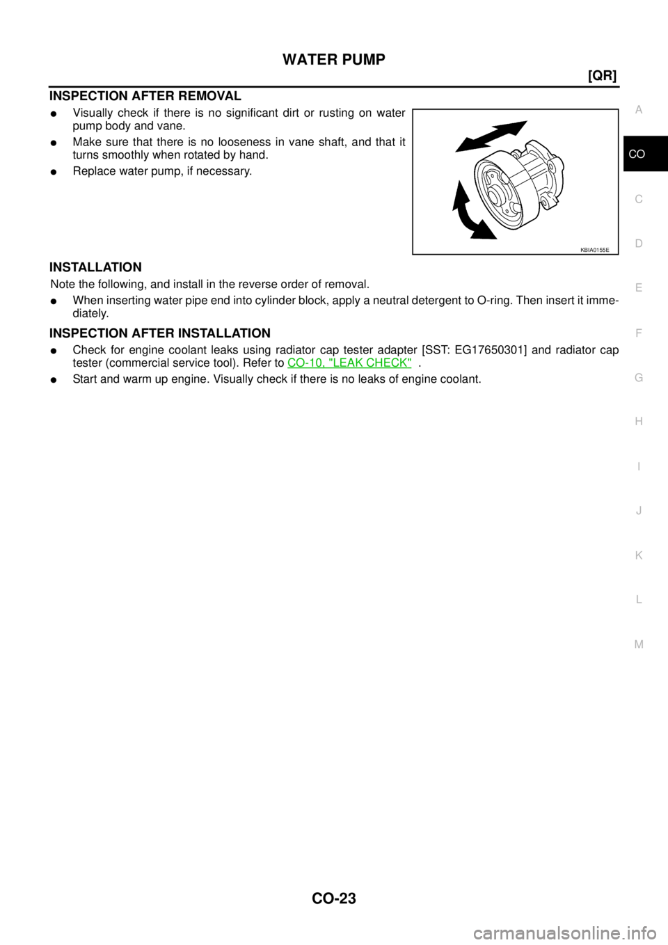
INSPECTION AFTER REMOVAL
�Visually check if there is no significant dirt or rusting on water
pump body and vane.
�Make sure that there is no looseness in vane shaft, and that it
turns smoothly when rotated by hand.
�Replace water pump, if necessary.
INSTALLATION
Note the following, and install in the reverse order of removal.
�When inserting water pipe end into cylinder block, apply a neutral detergent to O-ring. Then insert it imme-
diately.
INSPECTION AFTER INSTALLATION
�Check for engine coolant leaks using radiator cap tester adapter [SST: EG17650301] and radiator cap
tester (commercial service tool). Refer to CO-10, "
LEAK CHECK" .
�Start and warm up engine. Visually check if there is no leaks of engine coolant.
KBIA0155E
Page 977 of 3502
![NISSAN TEANA 2003 Service Manual THERMOSTAT AND WATER CONTROL VALVE
CO-25
[QR]
C
D
E
F
G
H
I
J
K
L
MA
CO
INSPECTION AFTER REMOVAL
�Place a string so that it is caught in the valves of thermostat and
water control valve. Immerse ful](/manual-img/5/57392/w960_57392-976.png "NISSAN TEANA 2003 Service Manual THERMOSTAT AND WATER CONTROL VALVE
CO-25
[QR]
C
D
E
F
G
H
I
J
K
L
MA
CO
INSPECTION AFTER REMOVAL
�Place a string so that it is caught in the valves of thermostat and
water control valve. Immerse ful")
THERMOSTAT AND WATER CONTROL VALVE
CO-25
[QR]
C
D
E
F
G
H
I
J
K
L
MA
CO
INSPECTION AFTER REMOVAL
�Place a string so that it is caught in the valves of thermostat and
water control valve. Immerse fully in a container filled with water.
Heat while stirring. (The example in the figure shows thermo-
stat.)
�The valve opening temperature is the temperature at which the
valve opens and falls from the thread.
�Continue heating. Check the maximum valve lift amount.
NOTE:
The maximum valve lift amount standard temperature for water
control valve is the reference value.
�After checking the maximum valve lift amount, lower the water
temperature and check the valve closing temperature.
Standard:
�If out of the standard, replace either or both thermostat and water control valve.
INSTALLATION
Note the following, and install in the reverse order of removal.
Thermostat and Water Control Valve
�Install thermostat with making rubber ring groove fit to thermo-
stat flange with the whole circumference. (The example in the
figure shows thermostat.)
NOTE:
Same procedure is applied for installation of water control valve.
�Install thermostat with jiggle valve facing upwards. (The position
deviation may be within the range of 20 degrees as shown in the
figure.)
�Install water control valve with the arrow facing up and the frame
center part facing upwards. (The position deviation may be
within the range of 20 degrees as shown in the figure.)
Heater Pipe Installation
Apply a neutral detergent to O-ring, then quickly insert the insertion part of heater pipe into cylinder block.
INSPECTION AFTER INSTALLATION
�Check for leaks of engine coolant using radiator cap tester adapter [SST: EG17650301] and a radiator cap
tester (commercial service tool). Refer to CO-10, "
LEAK CHECK" .
�Start and warm up engine. Visually check if there is no leaks of engine coolant and A/T fluid.
SLC252B
Items Thermostat Water control valve
Valve opening temperature 80.5 - 83.5°C (177 - 182°F) 93.5 - 96.5°C (200 - 206°F)
Maximum valve lift 8 mm/ 95°C (0.315 in/ 203°F) 8 mm/ 108°C (0.315 in/ 226°F)
Valve closing temperature 77°C (171°F) 90°C (194°F)
PBIC0157E
PBIC0158E
Page 978 of 3502
CO-26
[QR]
SERVICE DATA AND SPECIFICATIONS (SDS)
SERVICE DATA AND SPECIFICATIONS (SDS)PFP:00030
Standard and LimitBBS005AC
ENGINE COOLANT CAPACITY (APPROXIMATE)
Unit: (lmp qt)
THERMOSTAT
WATER CONTROL VALVE
*: Reference data
RADIATOR
Unit: kPa (bar, kg/cm2 , psi)
Engine coolant capacity (With reservoir tank at “MAX” level) 7.4 (6-1/2)
Reservoir tank engine coolant capacity (At “MAX” level) 0.8 (3/4)
Valve opening temperature 80.5 - 83.5°C (177 - 182°F)
Maximum valve lift 8 mm/ 95°C (0.315 in/ 203°F)
Valve closing temperature 77°C (171°F)
Valve opening temperature 93.5 - 96.5°C (200 - 206°F)
Maximum valve lift 8 mm/ 108°C (0.315 in/ 226°F)*
Valve closing temperature 90°C (194°F)
Cap relief pressureStandard 78 - 98 (0.78 - 0.98, 0.8 - 1.0, 11- 14)
Limit 59 (0.59, 0.6, 9)
Leakage test pressure 157 (1.57, 1.6, 23)
Page 979 of 3502
![NISSAN TEANA 2003 Service Manual PRECAUTIONS
CO-27
[VQ]
C
D
E
F
G
H
I
J
K
L
MA
CO
[VQ]PRECAUTIONSPFP:00001
Precautions for Supplemental Restraint System (SRS) “AIR BAG” and “SEAT
BELT PRE-TENSIONER”
BBS004WR
The Supplement](/manual-img/5/57392/w960_57392-978.png "NISSAN TEANA 2003 Service Manual PRECAUTIONS
CO-27
[VQ]
C
D
E
F
G
H
I
J
K
L
MA
CO
[VQ]PRECAUTIONSPFP:00001
Precautions for Supplemental Restraint System (SRS) “AIR BAG” and “SEAT
BELT PRE-TENSIONER”
BBS004WR
The Supplement")
PRECAUTIONS
CO-27
[VQ]
C
D
E
F
G
H
I
J
K
L
MA
CO
[VQ]PRECAUTIONSPFP:00001
Precautions for Supplemental Restraint System (SRS) “AIR BAG” and “SEAT
BELT PRE-TENSIONER”
BBS004WR
The Supplemental Restraint System such as “AIR BAG” and “SEAT BELT PRE-TENSIONER”, used along
with a front seat belt, helps to reduce the risk or severity of injury to the driver and front passenger for certain
types of collision. Information necessary to service the system safely is included in the SRS and SB section of
this Service Manual.
WARNING:
�To avoid rendering the SRS inoperative, which could increase the risk of personal injury or death
in the event of a collision which would result in air bag inflation, all maintenance must be per-
formed by an authorized NISSAN/INFINITI dealer.
�Improper maintenance, including incorrect removal and installation of the SRS, can lead to per-
sonal injury caused by unintentional activation of the system. For removal of Spiral Cable and Air
Bag Module, see the SRS section.
�Do not use electrical test equipment on any circuit related to the SRS unless instructed to in this
Service Manual. SRS wiring harnesses can be identified by yellow and/or orange harnesses or
harness connectors.
Precautions for Liquid GasketBBS004WS
REMOVAL OF LIQUID GASKET SEALING
�After removing mounting nuts and bolts, separate the mating
surface using seal cutter (SST) and remove old liquid gasket
sealing.
CAUTION:
Be careful not to damage the mating surfaces.
�Tap seal cutter to insert it, and then slide it by tapping on the
side as shown in the figure.
�In areas where seal cutter (SST) is difficult to use, use plastic
hammer to lightly tap the parts, to remove it.
CAUTION:
If for some unavoidable reason tool such as screwdriver is
used, be careful not to damage the mating surfaces.
LIQUID GASKET APPLICATION PROCEDURE
1. Using scraper, remove old liquid gasket adhering to the liquid
gasket application surface and the mating surface.
�Remove liquid gasket completely from the groove of the liquid
gasket application surface, mounting bolts, and bolt holes.
2. Wipe the liquid gasket application surface and the mating sur-
face with white gasoline (lighting and heating use) to remove
adhering moisture, grease and foreign materials.
3. Attach liquid gasket tube to tube presser (SST).
Use Genuine Liquid Gasket or equivalent.
4. Apply liquid gasket without breaks to the specified location with
the specified dimensions.
�If there is a groove for the liquid gasket application, apply liq-
uid gasket to the groove.
PBIC0275E
PBIC0003E
PBIC2160E
Page 980 of 3502
CO-28
[VQ]
PRECAUTIONS
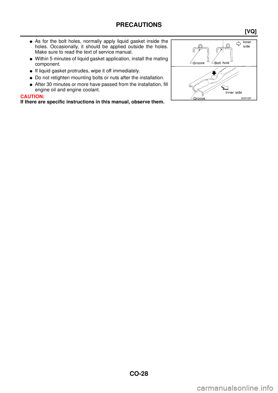
�As for the bolt holes, normally apply liquid gasket inside the
holes. Occasionally, it should be applied outside the holes.
Make sure to read the text of service manual.
�Within 5 minutes of liquid gasket application, install the mating
component.
�If liquid gasket protrudes, wipe it off immediately.
�Do not retighten mounting bolts or nuts after the installation.
�After 30 minutes or more have passed from the installation, fill
engine oil and engine coolant.
CAUTION:
If there are specific instructions in this manual, observe them.
SEM159F
Page 981 of 3502
PREPARATION
CO-29
[VQ]
C
D
E
F
G
H
I
J
K
L
MA
CO
PREPARATIONPFP:00002
Special Service ToolsBBS004WT
Commercial Service ToolsBBS004WU
Tool number
Tool nameDescription
EG17650301
Radiator cap tester adapterAdapting radiator cap tester to radiator cap
and radiator filler neck
a: 28 (1.10) dia.
b: 31.4 (1.236) dia.
c: 41.3 (1.626) dia.
Unit: mm (in)
KV99103510
Radiator plate pliers AInstalling radiator upper and lower tanks
KV99103520
Radiator plate pliers BRemoving radiator upper and lower tanks
KV10111100
Seal cutterRemoving chain tensioner cover and water
pump cover
WS39930000
Tube presserPressing the tube of liquid gasket
S-NT564
S-NT224
S-NT225
NT046
S-NT052
Tool nameDescription
Radiator cap tester Checking radiator and radiator cap
PBIC1982E
![NISSAN TEANA 2003 Service Manual RADIATOR (ALUMINUM TYPE)
CO-19
[QR]
C
D
E
F
G
H
I
J
K
L
MA
CO
4. Make sure that the rim is completely crimped down.
5. Make sure that there is no leakage. Refer to CO-19, "
INSPECTION" .
INSPECTION](/manual-img/5/57392/w960_57392-970.png "NISSAN TEANA 2003 Service Manual RADIATOR (ALUMINUM TYPE)
CO-19
[QR]
C
D
E
F
G
H
I
J
K
L
MA
CO
4. Make sure that the rim is completely crimped down.
5. Make sure that there is no leakage. Refer to CO-19, \"
INSPECTION\" .
INSPECTION")
![NISSAN TEANA 2003 Service Manual CO-26
[QR]
SERVICE DATA AND SPECIFICATIONS (SDS)
SERVICE DATA AND SPECIFICATIONS (SDS)PFP:00030
Standard and LimitBBS005AC
ENGINE COOLANT CAPACITY (APPROXIMATE)
Unit: (lmp qt)
THERMOSTAT
WATER CO](/manual-img/5/57392/w960_57392-977.png "NISSAN TEANA 2003 Service Manual CO-26
[QR]
SERVICE DATA AND SPECIFICATIONS (SDS)
SERVICE DATA AND SPECIFICATIONS (SDS)PFP:00030
Standard and LimitBBS005AC
ENGINE COOLANT CAPACITY (APPROXIMATE)
Unit: (lmp qt)
THERMOSTAT
WATER CO")
![NISSAN TEANA 2003 Service Manual PREPARATION
CO-29
[VQ]
C
D
E
F
G
H
I
J
K
L
MA
CO
PREPARATIONPFP:00002
Special Service ToolsBBS004WT
Commercial Service ToolsBBS004WU
Tool number
Tool nameDescription
EG17650301
Radiator cap tester a](/manual-img/5/57392/w960_57392-980.png "NISSAN TEANA 2003 Service Manual PREPARATION
CO-29
[VQ]
C
D
E
F
G
H
I
J
K
L
MA
CO
PREPARATIONPFP:00002
Special Service ToolsBBS004WT
Commercial Service ToolsBBS004WU
Tool number
Tool nameDescription
EG17650301
Radiator cap tester a")