Page 2961 of 3502
![NISSAN TEANA 2003 Service Manual OIL PUMP
LU-11
[QR]
C
D
E
F
G
H
I
J
K
L
MA
LU
OIL PUMPPFP:15010
Removal and InstallationBBS0059S
REMOVAL
Remove front cover. Refer to EM-53, "TIMING CHAIN" .
NOTE:
Oil pump is built into front cove](/manual-img/5/57392/w960_57392-2960.png "NISSAN TEANA 2003 Service Manual OIL PUMP
LU-11
[QR]
C
D
E
F
G
H
I
J
K
L
MA
LU
OIL PUMPPFP:15010
Removal and InstallationBBS0059S
REMOVAL
Remove front cover. Refer to EM-53, \"TIMING CHAIN\" .
NOTE:
Oil pump is built into front cove")
OIL PUMP
LU-11
[QR]
C
D
E
F
G
H
I
J
K
L
MA
LU
OIL PUMPPFP:15010
Removal and InstallationBBS0059S
REMOVAL
Remove front cover. Refer to EM-53, "TIMING CHAIN" .
NOTE:
Oil pump is built into front cover.
INSTALLATION
Note the following, and install in the reverse order of removal.
�When installing, align oil pump drive spacer flat faces with inner rotor flat faces.
INSPECTION AFTER INSTALLATION
1. Check the engine oil level. Refer to LU-7, "ENGINE OIL" .
2. Start engine, and make sure there is no leaks of engine oil.
3. Stop engine and wait for 10 minutes.
4. Check the engine oil level and adjust engine oil. Refer to LU-7, "
ENGINE OIL" .
Disassembly and AssemblyBBS0059T
DISASSEMBLY
1. Remove oil pump cover.
2. Remove inner rotor and outer rotor from front cover.
3. After removing regulator valve plug, remove regulator valve spring and regulator valve.
PBIC2430E
1. Front cover (Oil pump body is united) 2. Outer rotor 3. Inner rotor
4. Oil pump cover 5. Regulator valve 6. Regulator valve spring
7. Regulator valve plug
Page 2969 of 3502
![NISSAN TEANA 2003 Service Manual ENGINE OIL
LU-19
[VQ]
C
D
E
F
G
H
I
J
K
L
MA
LU
ENGINE OILPFP:KLA92
InspectionBBS004WK
ENGINE OIL LEVEL
NOTE:
Before starting engine, put vehicle horizontally and check the engine oil level. If engi](/manual-img/5/57392/w960_57392-2968.png "NISSAN TEANA 2003 Service Manual ENGINE OIL
LU-19
[VQ]
C
D
E
F
G
H
I
J
K
L
MA
LU
ENGINE OILPFP:KLA92
InspectionBBS004WK
ENGINE OIL LEVEL
NOTE:
Before starting engine, put vehicle horizontally and check the engine oil level. If engi")
ENGINE OIL
LU-19
[VQ]
C
D
E
F
G
H
I
J
K
L
MA
LU
ENGINE OILPFP:KLA92
InspectionBBS004WK
ENGINE OIL LEVEL
NOTE:
Before starting engine, put vehicle horizontally and check the engine oil level. If engine is already started, stop
it and allow 10 minutes before checking.
1. Pull out oil level gauge and wipe it clean.
2. Insert oil level gauge and make sure the engine oil level is within
the range shown in the figure.
3. If it is out of range, adjust it.
ENGINE OIL APPEARANCE
�Check engine oil for white turbidity or heavy contamination.
�If engine oil becomes turbid and white, it is highly probable that it is contaminated with engine coolant.
Repair or replace damaged parts.
ENGINE OIL LEAKAGE
Check for engine oil leakage around the following areas:
�Oil pan
�Oil pan drain plug
�Oil pressure switch
�Oil filter
�Oil cooler (VQ35DE)
�Water pump cover
�Chain tensioner cover
�Intake valve timing control cover and intake valve timing control solenoid valve
�Mating surface between cylinder block and cylinder head
�Mating surface between cylinder head and rocker cover
�Mating surface between front timing chain case and rear timing chain case
�Mating surface between rear timing chain case and cylinder block
�Crankshaft oil seals (front and rear)
PBIC0249E
Page 2975 of 3502
![NISSAN TEANA 2003 Service Manual OIL PUMP
LU-25
[VQ]
C
D
E
F
G
H
I
J
K
L
MA
LU
OIL PUMPPFP:15010
Removal and InstallationBBS004WO
REMOVAL
1. Remove oil pans (lower and upper) and oil strainer. Refer to EM-145, "OIL PAN AND OIL STRA](/manual-img/5/57392/w960_57392-2974.png "NISSAN TEANA 2003 Service Manual OIL PUMP
LU-25
[VQ]
C
D
E
F
G
H
I
J
K
L
MA
LU
OIL PUMPPFP:15010
Removal and InstallationBBS004WO
REMOVAL
1. Remove oil pans (lower and upper) and oil strainer. Refer to EM-145, \"OIL PAN AND OIL STRA")
OIL PUMP
LU-25
[VQ]
C
D
E
F
G
H
I
J
K
L
MA
LU
OIL PUMPPFP:15010
Removal and InstallationBBS004WO
REMOVAL
1. Remove oil pans (lower and upper) and oil strainer. Refer to EM-145, "OIL PAN AND OIL STRAINER" .
2. Remove front timing chain case and timing chain (primary). Refer to EM-173, "
TIMING CHAIN" .
3. Remove oil pump assembly.
INSTALLATION
Note the following, and install in the reverse order of removal.
�When installing, align crankshaft flat faces with inner rotor flat faces.
INSPECTION AFTER INSTALLATION
1. Check the engine oil level. Refer to LU-19, "ENGINE OIL" .
2. Start engine, and check there is no leaks of engine oil.
3. Stop engine and wait for 10 minutes.
4. Check the engine oil level and add engine oil. Refer to LU-19, "
ENGINE OIL" .
Disassembly and AssemblyBBS004WP
DISASSEMBLY
1. Remove oil pump cover.
2. Remove oil pump inner rotor and oil pump outer rotor from oil pump body.
3. After removing regulator valve plug, remove regulator valve spring and regulator valve.
1. Oil pump body 2. Oil pump outer rotor 3. Oil pump inner rotor
4. Oil pump cover 5. Regulator valve plug 6. Regulator valve spring
7. Regulator valve
PBIC2509E
Page 3016 of 3502
![NISSAN TEANA 2003 Service Manual MA-38
CHASSIS AND BODY MAINTENANCE
Changing CVT FluidBLS0009I
1. Warm up CVT fluid by driving the vehicle for 10 minutes.
�: Vehicle front
�Radiator (2)
�CVT fluid cooler hose [inlet side (3)]
�Tran](/manual-img/5/57392/w960_57392-3015.png "NISSAN TEANA 2003 Service Manual MA-38
CHASSIS AND BODY MAINTENANCE
Changing CVT FluidBLS0009I
1. Warm up CVT fluid by driving the vehicle for 10 minutes.
�: Vehicle front
�Radiator (2)
�CVT fluid cooler hose [inlet side (3)]
�Tran")
MA-38
CHASSIS AND BODY MAINTENANCE
Changing CVT FluidBLS0009I
1. Warm up CVT fluid by driving the vehicle for 10 minutes.
�: Vehicle front
�Radiator (2)
�CVT fluid cooler hose [inlet side (3)]
�Transaxle assembly (4)
2. Drain CVT fluid from CVT fluid cooler hose [outlet side (1)] and
refill with new CVT fluid at CVT fluid charging pipe with the
engine running at idle speed.
3. Refill until new CVT fluid comes out from CVT fluid cooler hose
[outlet side (1)].
About 30 to 50% extra fluid will be required for this procedure.
CAUTION:
�Use only Genuine NISSAN CVT Fluid NS-2. Do not mix with other fluid.
�Using CVT fluid other than Genuine NISSAN CVT Fluid NS-2 will deteriorate in driveability and
CVT durability, and may damage the CVT, which is not covered by the warranty.
�When filling CVT fluid, take care not to scatter heat generating parts such as exhaust.
�Delete CVT fluid deterioration date with CONSULT-II after changing CVT fluid. Refer to CVT-46,
"Check CVT Fluid Deterioration Date" .
4. Check fluid leakage, fluid level and condition.
Balancing Wheels (Bonding Weight Type)BLS0005W
REMOVAL
1. Remove inner and outer balance weights from the road wheel.
CAUTION:
Be careful not to scratch the road wheel during removal.
2. Using releasing agent, remove double-faced adhesive tape from the road wheel.
CAUTION:
�Be careful not to scratch the road wheel during removal.
�After removing double-faced adhesive tape, wipe clean traces of releasing agent from the road
wheel.
WHEEL BALANCE ADJUSTMENT
�If a tire balance machine has adhesion balance weight mode settings and drive-in weight mode setting,
select and adjust a drive-in weight mode suitable for road wheels.
1. Set road wheel on wheel balancer using the center hole as a guide. Start the tire balance machine.
2. When inner and outer unbalance values are shown on the wheel balancer indicator, multiply outer unbal-
ance value by 5/3 to determine balance weight that should be used. Select the outer balance weight with
a value closest to the calculated value above and install it to the designated outer position of, or at the
designated angle in relation to the road wheel.
CAUTION:
�Do not install the inner balance weight before installing the outer balance weight.CVT fluid:
Genuine NISSAN CVT Fluid NS-2
Fluid capacity:
Approx. 10.2 (9 lmp qt)
SCIA6088E
Page 3019 of 3502
CHASSIS AND BODY MAINTENANCE
MA-41
C
D
E
F
G
H
I
J
K
MA
B
MA
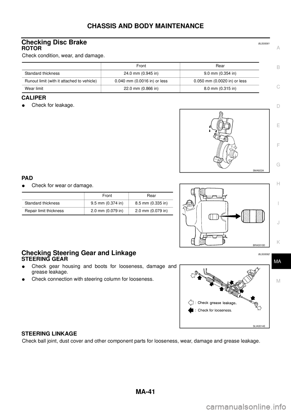
Checking Disc BrakeBLS00061
ROTOR
Check condition, wear, and damage.
CALIPER
�Check for leakage.
PA D
�Check for wear or damage.
Checking Steering Gear and LinkageBLS00062
STEERING GEAR
�Check gear housing and boots for looseness, damage and
grease leakage.
�Check connection with steering column for looseness.
STEERING LINKAGE
Check ball joint, dust cover and other component parts for looseness, wear, damage and grease leakage.
Front Rear
Standard thickness 24.0 mm (0.945 in) 9.0 mm (0.354 in)
Runout limit (with it attached to vehicle) 0.040 mm (0.0016 in) or less 0.050 mm (0.0020 in) or less
Wear limit 22.0 mm (0.866 in) 8.0 mm (0.315 in)
SMA922A
Front Rear
Standard thickness 9.5 mm (0.374 in) 8.5 mm (0.335 in)
Repair limit thickness 2.0 mm (0.079 in) 2.0 mm (0.079 in)
BRA0010D
SLIA0014E
Page 3020 of 3502

MA-42
CHASSIS AND BODY MAINTENANCE
Checking Power Steering Fluid and LinesBLS00063
Check fluid level in reservoir tank with engine off.
Use “HOT” range at fluid temperatures of 50 to 80°C (122 to 176°F)
or “COLD” range at fluid temperatures of 0 to 30°C (32 to 86°F).
CAUTION:
�Do not overfill.
�Recommended fluid is DEXRONTM III type ATF or equiva-
lent.
Refer to MA-14, "
RECOMMENDED FLUIDS AND LUBRI-
CANTS" .
�Check lines for improper attachment, leaks, cracks, dam-
age, loose connections, chafing and deterioration.
�Check rack boots for accumulation of power steering fluid.
Axle and Suspension PartsBLS00064
Check front and rear axle and suspension parts for excessive play,
cracks, wear or other damage.
�Shake each wheel to check for excessive play.
�Check wheel bearings for smooth operation.
�Check axle and suspension nuts and bolts for looseness.
�Check strut (shock absorber) for oil leakage or other damage.
�Check suspension ball joint for grease leakage and ball joint
dust cover for cracks or other damage.
SST850C
SST851C
SMA525A
SFA392B
Page 3029 of 3502

PARKING BRAKE CONTROL
PB-3
C
D
E
G
H
I
J
K
L
MA
B
PB
PARKING BRAKE CONTROLPFP:36010
ComponentsBFS000CE
Removal and InstallationBFS000CF
REMOVAL
1. Release parking brake.
2. Remove instrument driver lower panel. Refer to IP-10, "
INSTRUMENT PANEL ASSEMBLY" .
3. Disconnect parking brake warning lamp switch connector.
4. Remove adjusting nut, and then separate device assembly and front cable.
5. Remove device assembly from vehicle.
6. Remove center console. Refer to IP-10, "
INSTRUMENT PANEL ASSEMBLY" .
7. Remove front cable mounting bolts.
8. Remove applicable heat insulator from vehicle.
9. Remove rear tyres from vehicle.
10. Remove center muffler. Refer to EX-2, "
EXHAUST SYSTEM" .
11. Remove rear brake caliper and disc rotor. Refer to BR-35, "
Removal and Installation of Brake Caliper
Assembly" .
12. Remove parking brake shoe, and then remove rear cable from toggle lever. Refer to PB-5, "
PA R K I N G
BRAKE SHOE" .
13. Remove rear cable mounting nuts and bolts, and then remove rear cable from vehicle.
1. Device assembly 2. Parking brake warning lamp switch 3. Spring insulator
4. Return spring 5. Adjusting nut 6. Pedal cover
7. Front cable 8. Equalizer
(Assemble to front cable.)9. Return spring
10. Rear left cable 11. Rear right cable 12. Pin
SFIA2503E
Page 3051 of 3502

PG-17
C
D
E
F
G
H
I
J
L
MA
B
PG
IPDM E/R (INTELLIGENT POWER DISTRIBUTION MODULE ENGINE ROOM)
PFP:284B7
System DescriptionBKS0024N
�IPDM E")
IPDM E/R (INTELLIGENT POWER DISTRIBUTION MODULE ENGINE ROOM)
PG-17
C
D
E
F
G
H
I
J
L
MA
B
PG
IPDM E/R (INTELLIGENT POWER DISTRIBUTION MODULE ENGINE ROOM)
PFP:284B7
System DescriptionBKS0024N
�IPDM E/R (Intelligent Power Distribution Module Engine Room) integrates the relay box and fuse block
which were originally placed in engine room. It controls integrated relay via IPDM E/R control circuit.
�IPDM E/R-integrated control circuit performs ON-OFF operation of relay, CAN communication control, oil
pressure switch signal, hood switch signal reception, etc.
�It controls operation of each electrical part via ECM, BCM and CAN communication lines.
CAUTION:
None of the IPDM E/R-integrated relays can be removed.
SYSTEMS CONTROLLED BY IPDM E/R
FAIL-SAFE CONTROL
�When CAN communication with other control units is impossible, IPDM E/R performs fail-safe control.
After CAN communication recovers normally, it also returns to normal control.
�Operation of control parts by IPDM E/R during fail-safe mode is as follows:
Control system Transmit control unit Control part
Lamp control BCM
�Headlamp (HI, LO)
�Parking, license plate and tail lamps
�Front fog lamp
Wiper control BCM Front wiper
Rear window defogger control BCM Rear window defogger
A/C compressor control ECM A/C compressor (magnet clutch)
Cooling fan control ECM Cooling fan
Horn control BCM Horn
Controlled system Fail-safe mode
Headlamp
�With the ignition switch ON, low beam headlamp is ON.
�With the ignition switch OFF, low beam headlamp is OFF.
Parking, license plate and tail lamps
�With the ignition switch ON, parking, license plate and tail lamps are ON.
�With the ignition switch OFF, parking, license plate and tail lamps are OFF.
Cooling fan
�With the ignition switch ON, cooling fan HI operates.
�With the ignition switch OFF, cooling fan stops.
Front wiperUntil the ignition switch is turned OFF, front wiper LO and HI remains in the same status it was
in just before fail−safe control was initiated.
Rear window defogger Rear window defogger is OFF.
A/C compressor A/C compressor is OFF.
Front fog lamp Front fog lamp is OFF.