Page 2287 of 3502
TIMING CHAIN
EM-179
[VQ]
C
D
E
F
G
H
I
J
K
L
MA
EM
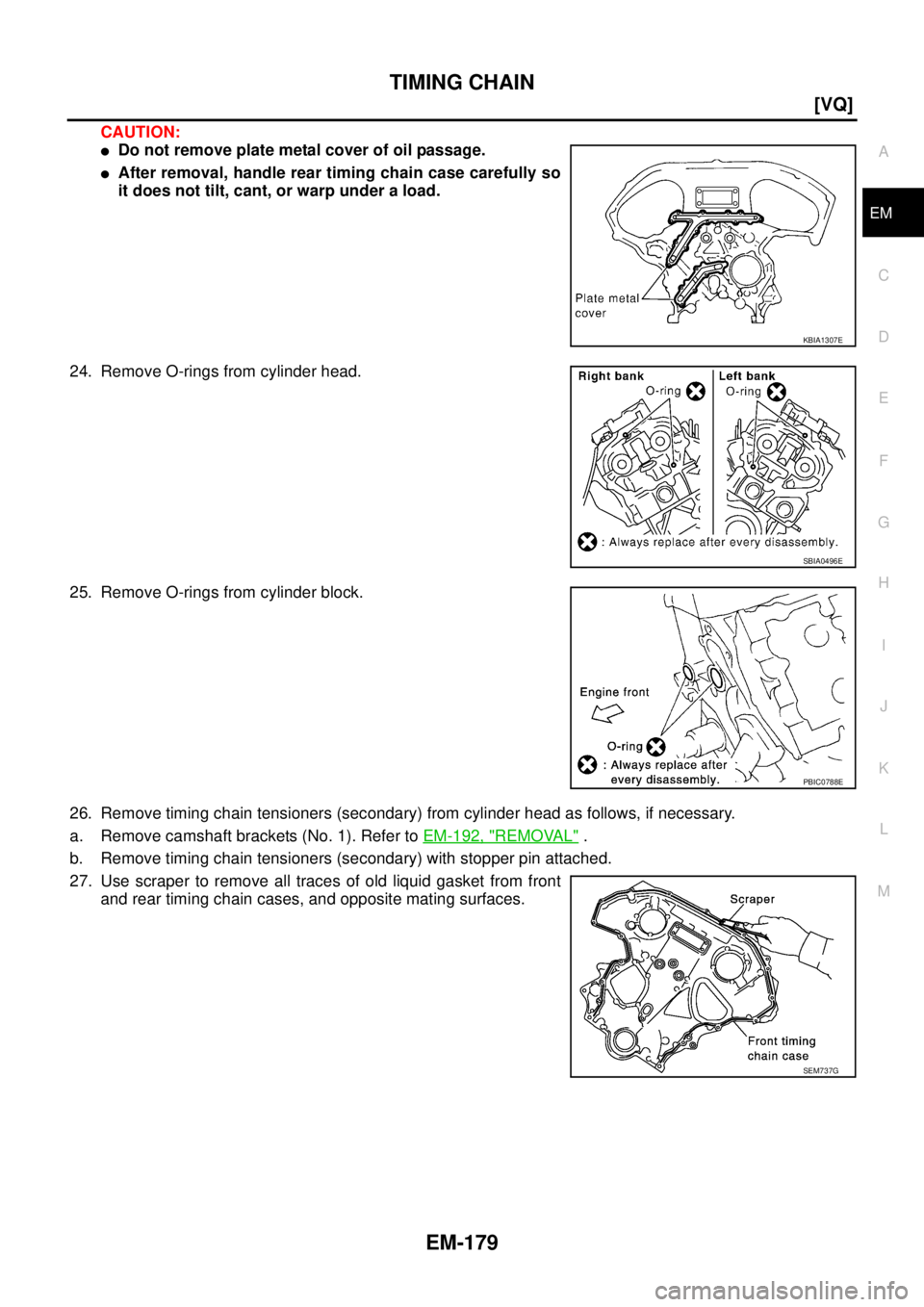
CAUTION:
�Do not remove plate metal cover of oil passage.
�After removal, handle rear timing chain case carefully so
it does not tilt, cant, or warp under a load.
24. Remove O-rings from cylinder head.
25. Remove O-rings from cylinder block.
26. Remove timing chain tensioners (secondary) from cylinder head as follows, if necessary.
a. Remove camshaft brackets (No. 1). Refer to EM-192, "
REMOVAL" .
b. Remove timing chain tensioners (secondary) with stopper pin attached.
27. Use scraper to remove all traces of old liquid gasket from front
and rear timing chain cases, and opposite mating surfaces.
KBIA1307E
SBIA0496E
PBIC0788E
SEM737G
Page 2296 of 3502
EM-188
[VQ]
TIMING CHAIN
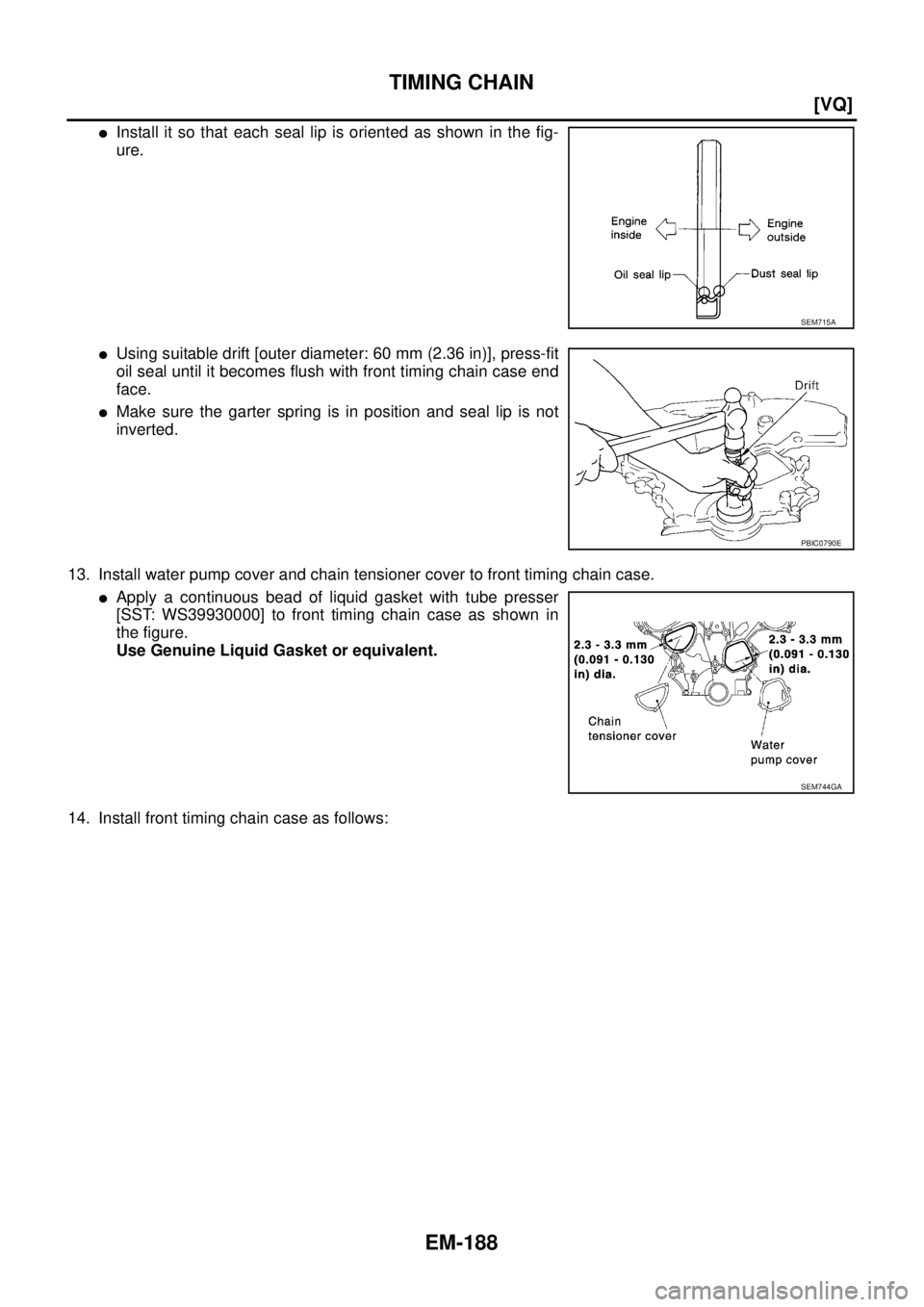
�Install it so that each seal lip is oriented as shown in the fig-
ure.
�Using suitable drift [outer diameter: 60 mm (2.36 in)], press-fit
oil seal until it becomes flush with front timing chain case end
face.
�Make sure the garter spring is in position and seal lip is not
inverted.
13. Install water pump cover and chain tensioner cover to front timing chain case.
�Apply a continuous bead of liquid gasket with tube presser
[SST: WS39930000] to front timing chain case as shown in
the figure.
Use Genuine Liquid Gasket or equivalent.
14. Install front timing chain case as follows:
SEM715A
PBIC0790E
SEM744GA
Page 2297 of 3502
![NISSAN TEANA 2003 Service Manual TIMING CHAIN
EM-189
[VQ]
C
D
E
F
G
H
I
J
K
L
MA
EM
a. Apply a continuous bead of liquid gasket with tube presser [SST:
WS39930000] to front timing chain case back side as shown in
the figure.
Use Ge](/manual-img/5/57392/w960_57392-2296.png "NISSAN TEANA 2003 Service Manual TIMING CHAIN
EM-189
[VQ]
C
D
E
F
G
H
I
J
K
L
MA
EM
a. Apply a continuous bead of liquid gasket with tube presser [SST:
WS39930000] to front timing chain case back side as shown in
the figure.
Use Ge")
TIMING CHAIN
EM-189
[VQ]
C
D
E
F
G
H
I
J
K
L
MA
EM
a. Apply a continuous bead of liquid gasket with tube presser [SST:
WS39930000] to front timing chain case back side as shown in
the figure.
Use Genuine Liquid Gasket or equivalent.
b. Install front timing chain case as to fit its dowel pin hole together dowel pin on rear timing chain case.
c. Tighten mounting bolts to the specified torque in numerical order
as shown in the figure.
�There are two types of mounting bolt. Refer to the following
for locating bolts.
d. After all bolts tightening, retighten them to the specified torque in
numerical order as shown in the figure.
CAUTION:
Be sure to wipe off any excessive liquid gasket leaking on surface mating with oil pan (upper).
e. After installing front timing chain case, check the surface height
difference between the following parts on the oil pan (upper)
mounting surface.
�If not within standard, repeat the installation procedure.
15. Install right and left intake valve timing control covers as follows:
a. Install new seal rings in shaft grooves.
PBIC2648E
M8 bolts : 1, 2
: 28.4 N·m (2.9 kg-m, 21 ft-lb)
M6 bolts : Except the above
: 12.7 N·m (1.3 kg-m, 9 ft-lb)
Standard
Front timing chain case to rear timing chain case:
−0.14 to 0.14 mm (−0.006 to 0.006 in)
SEM730G
SEM943G
Page 2298 of 3502
![NISSAN TEANA 2003 Service Manual EM-190
[VQ]
TIMING CHAIN
b. Apply a continuous bead of liquid gasket with tube presser [SST:
WS39930000] to intake valve timing control covers as shown in
the figure.
Use Genuine Liquid Gasket or eq](/manual-img/5/57392/w960_57392-2297.png "NISSAN TEANA 2003 Service Manual EM-190
[VQ]
TIMING CHAIN
b. Apply a continuous bead of liquid gasket with tube presser [SST:
WS39930000] to intake valve timing control covers as shown in
the figure.
Use Genuine Liquid Gasket or eq")
EM-190
[VQ]
TIMING CHAIN
b. Apply a continuous bead of liquid gasket with tube presser [SST:
WS39930000] to intake valve timing control covers as shown in
the figure.
Use Genuine Liquid Gasket or equivalent.
c. Install new collared O-ring in front timing chain case oil hole (left
and right sides).
d. Being careful not to move seal rings from the installation grooves, align dowel pins on front timing chain
case with the holes to install intake valve timing control covers.
e. Tighten mounting bolts in numerical order as shown in the fig-
ure.
16. Install crankshaft pulley as follows:
a. Install crankshaft pulley, taking care not to damage front oil seal.
�When press-fitting crankshaft pulley with plastic hammer, tap on its center portion (not circumference).
b. Fix crankshaft with pulley holder [SST: KV10109300].
c. Tighten crankshaft pulley bolt.
d. Place a matching mark (A) on crank pulley (1) aligning with the
matching (B) of crank pulley mounting bolt (2). Tighten the bolts
90 degrees (one marks).
SBIA0492E
PBIC2631E
PBIC0918E
: 44.1 N·m (4.5 kg-m, 33 ft-lb)
PBIC4627J
Page 2308 of 3502
![NISSAN TEANA 2003 Service Manual EM-200
[VQ]
CAMSHAFT
5. Tighten camshaft bracket bolts in the following steps, in numeri-
cal order as shown in the figure.
a. Tighten No. 7 to 10 in order as shown.
b. Tighten No. 1 to 6 in order a](/manual-img/5/57392/w960_57392-2307.png "NISSAN TEANA 2003 Service Manual EM-200
[VQ]
CAMSHAFT
5. Tighten camshaft bracket bolts in the following steps, in numeri-
cal order as shown in the figure.
a. Tighten No. 7 to 10 in order as shown.
b. Tighten No. 1 to 6 in order a")
EM-200
[VQ]
CAMSHAFT
5. Tighten camshaft bracket bolts in the following steps, in numeri-
cal order as shown in the figure.
a. Tighten No. 7 to 10 in order as shown.
b. Tighten No. 1 to 6 in order as shown.
c. Tighten No. 1 to 10 in numerical order as shown.
d. Tighten No. 1 to 10 in numerical order as shown.
CAUTION:
After tightening mounting bolts of camshaft brackets (No.
1), be sure to wipe off excessive liquid gasket from the
parts list below.
�Mating surface of rocker cover
�Mating surface of rear timing chain case
6. Measure the difference in levels between front end faces of
camshaft bracket (No. 1) and cylinder head.
�Measure two positions (both intake and exhaust side) for a
single bank.
�If measured value is out of the standard, re-install camshaft
bracket (No. 1).
7. Check and adjust the valve clearance. Refer to EM-202, "
Valve Clearance" .
8. Install in the reverse order of removal after this step. : 1.96 N·m (0.20 kg-m, 1 ft-lb)
: 1.96 N·m (0.20 kg-m, 1 ft-lb)
: 5.88 N·m (0.60 kg-m, 4 ft-lb)
: 10.4 N·m (1.1 kg-m, 8 ft-lb)
PBIC2050E
Standard : −0.14 to 0.14 mm (−0.006 to 0.006 in)
EMQ0044D
Page 2310 of 3502
![NISSAN TEANA 2003 Service Manual EM-202
[VQ]
CAMSHAFT
Summary of the inspection items:
* Transmission/transaxle/CVT fluid. power steering fluid, brake fluid, etc.
Valve ClearanceBBS004W2
INSPECTION
In cases of removing/installing o](/manual-img/5/57392/w960_57392-2309.png "NISSAN TEANA 2003 Service Manual EM-202
[VQ]
CAMSHAFT
Summary of the inspection items:
* Transmission/transaxle/CVT fluid. power steering fluid, brake fluid, etc.
Valve ClearanceBBS004W2
INSPECTION
In cases of removing/installing o")
EM-202
[VQ]
CAMSHAFT
Summary of the inspection items:
* Transmission/transaxle/CVT fluid. power steering fluid, brake fluid, etc.
Valve ClearanceBBS004W2
INSPECTION
In cases of removing/installing or replacing camshaft and valve-
related parts, or of unusual engine conditions due to changes in
valve clearance (found malfunctions during stating, idling or causing
noise), perform inspection as follows:
1. Remove rocker covers (right and left banks). Refer to EM-160, "
ROCKER COVER" .
2. Remove splash guard (RH).
3. Measure the valve clearance as follows:
a. Set No. 1 cylinder at TDC of its compression stroke.
�Rotate crankshaft pulley clockwise to align timing mark
(grooved line without color) with timing indicator.
�Make sure that intake and exhaust cam noses on No. 1 cylin-
der (engine front side of right bank) are located as shown in
the figure.
�If not, rotate crankshaft one revolution (360 degrees) and
align as shown in the figure.
Item Before starting engine Engine running After engine stopped
Engine coolant Level Leakage Level
Engine oil Level Leakage Level
Other oils and fluid* Level Leakage Level
Fuel Leakage Leakage Leakage
Exhaust gases — Leakage —
SEM713A
SEM918G
SEM418G
Page 2332 of 3502
![NISSAN TEANA 2003 Service Manual EM-224
[VQ]
ENGINE ASSEMBLY
�Do not start working until exhaust system and engine coolant are cool enough.
�If items or work required are not covered by the engine section, refer to the applicable s](/manual-img/5/57392/w960_57392-2331.png "NISSAN TEANA 2003 Service Manual EM-224
[VQ]
ENGINE ASSEMBLY
�Do not start working until exhaust system and engine coolant are cool enough.
�If items or work required are not covered by the engine section, refer to the applicable s")
EM-224
[VQ]
ENGINE ASSEMBLY
�Do not start working until exhaust system and engine coolant are cool enough.
�If items or work required are not covered by the engine section, refer to the applicable sections.
�Always use the support point specified for lifting.
�Use either 2-pole lift type or separate type lift as best you can. If board-on type is used for
unavoidable reasons, support at the rear axle jacking point with transmission jack or similar tool
before starting work, in preparation for the backward shift of center of gravity.
�For supporting points for lifting and jacking point at rear axle, refer to GI-37, "Garage Jack and
Safety Stand and 2-Pole Lift" .
REMOVAL
Outline
At first, remove engine and transaxle assembly with front suspension member from vehicle downward. Sepa-
rate front suspension member, and then separate engine from transaxle.
Preparation
1. Release fuel pressure. Refer to EC-392, "FUEL PRESSURE RELEASE" .
2. Drain engine coolant from radiator. Refer to CO-34, "
Changing Engine Coolant" .
CAUTION:
�Perform this step when engine is cold.
�Do not spill engine coolant on drive belts.
3. Remove the following parts:
�Engine cover; Refer to EM-133, "INTAKE MANIFOLD COLLECTOR" .
�Hood assembly; Refer to BL-13, "HOOD" .
�Front road wheels and tires.
�Undercover and splash guards (RH and LH).
�Air duct (inlet), air cleaner case (upper) with mass air flow sensor and air duct assembly; Refer to EM-
131, "AIR CLEANER AND AIR DUCT" .
�Battery, battery tray and battery tray bracket; Refer to SC-4, "BATTERY" .
�Drive belts; Refer to EM-128, "DRIVE BELTS" .
�Radiator, reservoir of radiator; Refer to CO-37, "RADIATOR" .
�Front wiper arm; Refer to WW-4, "FRONT WIPER AND WASHER SYSTEM" .
�Cowl top cover. Refer to EI-21, "COWL TOP" .
4. Disconnect engine room harness at the ECM side.
CAUTION:
To keep clean harness connector and avoid damage and foreign materials, cover them completely
with plastic bags or something similar.
Engine Room
1. Disconnect heater hoses. Refer to CO-52, "WATER OUTLET AND WATER PIPING" .
�Install plug to avoid leakage of engine coolant.
2. Remove EVAP hose. Refer to EM-133, "
INTAKE MANIFOLD COLLECTOR" .
3. Disconnect fuel feed hose (with fuel damper) quick connector at centralized under-floor piping side. Refer
to EM-155, "
FUEL INJECTOR AND FUEL TUBE" .
�Install plug to avoid leakage of fuel.
4. Disconnect shift control cable at transaxle side. Refer to AT- 2 1 3 , "
SHIFT CONTROL SYSTEM" .
5. Disconnect brake booster vacuum hose at engine side. Refer to EM-133, "
INTAKE MANIFOLD COLLEC-
TOR" .
6. Remove IPDM E/R mounting bolt and IPDM E/R bracket mounting bolts, and move it to aside. Refer to
PG-17, "
IPDM E/R (INTELLIGENT POWER DISTRIBUTION MODULE ENGINE ROOM)" .
7. Remove alternator. Refer to SC-27, "
CHARGING SYSTEM" .
8. Remove A/C compressor with piping connected, and temporarily secure it to aside. Refer to ATC-133,
"Components" .
9. Disconnect suction hoses of power steering oil pump at reservoir tank side.
�Install plug to avoid leakage of power steering fluid.
Page 2423 of 3502

FUEL LEVEL SENSOR UNIT, FUEL FILTER AND FUEL PUMP ASSEMBLY
FL-7
C
D
E
F
G
H
I
J
K
L
MA
FL
INSTALLATION
Note the following, and install in the reverse order of removal.
Fuel Level Sensor Unit, Fuel Filter and Fuel Pump Assembly
1. Install seal packing to fuel tank without any twist.
2. Align “B” with “A” as shown in the figure. Install fuel level sensor
unit, fuel filter and fuel pump assembly to fuel tank.
CAUTION:
Do not bend float arm during installing.
3. Tighten lock ring with lock ring wrench (commercial service tool).
CAUTION:
Install lock ring horizontally.
Quick Connector
Connect quick connector of fuel feed hose as follows:
1. Check the connection for damage or any foreign materials.
2. Align the connector with the tube, then insert the connector straight into the tube until a click sound is
heard.
3. After connecting, make sure that the connection is secure by following method.
�Visually confirm that the two tabs are connected to the connector.
�Pull the tube and the connector to make sure they are
securely connected.
Inspection Hole Cover
1. Install inspection hole cover with front mark (arrow) facing front of vehicle.
2. Lock clips by turning counter-clockwise.
INSPECTION AFTER INSTALLATION
Use the following procedure to check for fuel leaks.
1. Turn ignition switch “ON” (with engine stopped), then check connections for leaks by applying fuel pres-
sure to fuel piping.
2. Start engine and rev it up and make sure there are no fuel leaks at the fuel system connections.
A : Arrow mark (Fuel tank side)
B : Positioning mark
C : Fuel tank
: Vehicle front
PBIC4584J
PBIC1653E