Page 3216 of 3502

SB-6
SEAT BELTS
REMOVAL
1. Remove rear seat cushion. Refer to SE-116, "Removal and Installation of Seat Cushion" .
2. Remove outer anchor bolt and inner anchor bolt.
3. Remove rear seatback. Refer to SE-117, "
Removal and Installation of Seatback" .
4. Remove rear seatback finisher and rear pillar finisher. Refer to EI-38, "
Removal and Installation" .
5. Remove center seat belt shoulder anchor cover.
6. Remove rear parcel shelf finisher. Refer to EI-43, "
Removal and Installation" .
7. Remove seat belt retractor mounting anchor bolt.
8. Remove seat belt assembly.
INSTALLATION
Install in the reverse order of removal.
InspectionBHS0003T
INSPECTION AFTER ACCIDENT
After a collision, inspect for damage or distortion of retractor, seat belt anchor, floor anchor, or shoulder
anchor. Nissan recommends replacement of all seat belt assemblies in the following cases because these
impairments may lead to personal injury.
�After a collision
�When installation point of seat belt assembly on vehicle is damaged.
�When it does not operate normally.
INSPECTION FOR SEAT BELT RETRACTOR
1. Using seat belt warning lamp, make sure that it works normally.
NOTE:
When ignition is turned ON and driver seat belt is not in use, seat belt warning lamp is turned on. It is
turned off when driver seat belt is in use.
2. Check whether anchor bolts on seat belt retractor and buckle are securely tightened.
3. Check if seat belt shoulder anchor rotates freely and seat belt adjuster operates properly.
4. Retractor operation inspection
a. Pull out all webbing and check for twisting, cuts, or other damage.
b. Retract webbing. Check if the webbing is retracted smoothly and completely into the retractor. When web-
bing is not retracted smoothly due to dust or other reasons, perform the following procedure with “SEAT
BELT, TAPE SET”.
Inspection for Front Seat Belt Shoulder Anchor
1. Pull webbing out 50 cm or more.
2. Fix webbing near the belt exit with a clip.
3. Pass a thin wire into the through part of shoulder anchor and webbing. Remove the materials that are
stuck from the webbing by sliding the wire vertically along the surface of the webbing through part while
pulling both sides of wire tightly.
4. Clean the remaining dirt by cleaning the webbing through part with a clean cloth.
5. Apply tape to the shoulder anchor belt through part where webbing touches.
NOTE:
Be careful to apply tape with no wrinkling or looseness.
PHIA0397E
Page 3239 of 3502
STARTING SYSTEM
SC-21
C
D
E
F
G
H
I
J
L
MA
B
SC
VQ35DE MODELS
SKIB6768E
1. Magnetic switch assembly 2. Plate 3. Packing
4. Plate 5. Shift lever 6. Front bracket assembly
7. Pinion spring 8. Pinion assembly 9. Pinion stopper
10. Stopper ring 11. Brush holder assembly 12. Metal
13. Rear cover 14. Through-bolt 15. Armature assembly
16. Yoke assembly 17. Packing 18. Ball
19. Gear assembly 20. Gear shaft 21. Internal gear assembly
22. Clutch gear assembly
: N·m (kg-m, in-lb)
(H): High-temperature grease point
Page 3251 of 3502
CHARGING SYSTEM
SC-33
C
D
E
F
G
H
I
J
L
MA
B
SC
Disassembly and AssemblyBKS0027D
VQ23DE AND VQ35DE MODELS
PKIB9030E
1. Stator 2. Rear bearing 3. Rotor assembly
4. Retainer 5. Front bearing 6. Front cover
7. Pulley 8. Pulley nut 9. Fun guide
10. Double labyrinth seal 11. IC voltage regulator assembly 12. Diode assembly
13. Rear cover 14. Terminal set 15. Through-bolt
Page 3252 of 3502
SC-34
CHARGING SYSTEM
QR20DE MODELS
DISASSEMBLY
Rear Cover
1. Remove through-bolt (4).
2. Remove rear cover.
NOTE:
Rear cover may be hard to remove because a ring is used to
lock outer race of rear bearing. To facilitate removal of rear
cover, heat just bearing box section with a 200 W soldering iron
until the temperature increases by about 30 °C.
CAUTION:
Never use a heat gun, as it can damage diode assembly.
PKIC8724E
1. Stator 2. Rear bearing 3. Rotor assembly
4. Retainer 5. Front bearing 6. Front cover
7. Pulley 8. Fun guide 9. Double labyrinth seal
10. IC voltage regulator assembly 11. Diode assembly 12. Rear cover
13. Terminal set 14. Through-bolt
SEL032Z
Page 3253 of 3502
CHARGING SYSTEM
SC-35
C
D
E
F
G
H
I
J
L
MA
B
SC
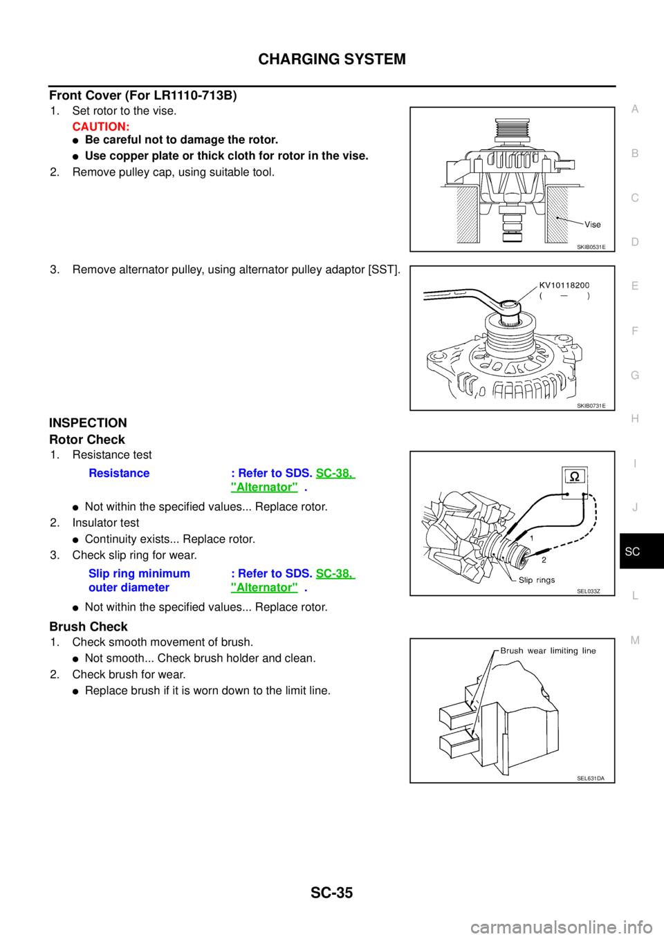
Front Cover (For LR1110-713B)
1. Set rotor to the vise.
CAUTION:
�Be careful not to damage the rotor.
�Use copper plate or thick cloth for rotor in the vise.
2. Remove pulley cap, using suitable tool.
3. Remove alternator pulley, using alternator pulley adaptor [SST].
INSPECTION
Rotor Check
1. Resistance test
�Not within the specified values... Replace rotor.
2. Insulator test
�Continuity exists... Replace rotor.
3. Check slip ring for wear.
�Not within the specified values... Replace rotor.
Brush Check
1. Check smooth movement of brush.
�Not smooth... Check brush holder and clean.
2. Check brush for wear.
�Replace brush if it is worn down to the limit line.
SKIB0531E
SKIB0731E
Resistance : Refer to SDS. SC-38,
"Alternator" .
Slip ring minimum
outer diameter: Refer to SDS. SC-38,
"Alternator" .SEL033Z
SEL631DA
Page 3264 of 3502
 pad/68239-")
SE-8
SQUEAK AND RATTLE TROUBLE DIAGNOSES
FELT CLOTHTAPE
Used to insulate where movement does not occur. Ideal for instrument panel applications.
68370-4B000: 15 × 25 mm (0.59 × 0.98 in) pad/68239-13E00: 5 mm (0.20 in) wide tape roll
The following materials, not available through NISSAN Parts Department, can also be used to repair squeaks
and rattles.
UHMW(TEFLON) TAPE
Insulates where slight movement is present. Ideal for instrument panel applications.
SILICONE GREASE
Used in place of UHMW tape that will be visible or not fit.
Note: Will only last a few months.
SILICONE SPRAY
Use when grease cannot be applied.
DUCT TAPE
Use to eliminate movement.
CONFIRM THE REPAIR
Confirm that the cause of a noise is repaired by test driving the vehicle. Operate the vehicle under the same
conditions as when the noise originally occurred. Refer to the notes on the Diagnostic Worksheet.
Generic Squeak and Rattle TroubleshootingBIS001TO
Refer to Table of Contents for specific component removal and installation information.
INSTRUMENT PANEL
Most incidents are caused by contact and movement between:
1. Cluster lid A and instrument panel
2. Acrylic lens and combination meter housing
3. Instrument panel to front pillar garnish
4. Instrument panel to windshield
5. Instrument panel mounting pins
6. Wiring harnesses behind the combination meter
7. A/C defroster duct and duct joint
These incidents can usually be located by tapping or moving the components to duplicate the noise or by
pressing on the components while driving to stop the noise. Most of these incidents can be repaired by apply-
ing felt cloth tape or silicon spray (in hard to reach areas). Urethane pads can be used to insulate wiring har-
ness.
CAUTION:
Do not use silicone spray to isolate a squeak or rattle. If you saturate the area with silicone, you will
not be able to recheck the repair.
CENTER CONSOLE
Components to pay attention to include:
1. Shifter assembly cover to finisher
2. A/C control unit and cluster lid C
3. Wiring harnesses behind audio and A/C control unit
The instrument panel repair and isolation procedures also apply to the center console.
DOORS
Pay attention to the:
1. Finisher and inner panel making a slapping noise
2. Inside handle escutcheon to door finisher
3. Wiring harnesses tapping
4. Door striker out of alignment causing a popping noise on starts and stops
Tapping or moving the components or pressing on them while driving to duplicate the conditions can isolate
many of these incidents. You can usually insulate the areas with felt cloth tape or insulator foam blocks to
repair the noise.
Page 3354 of 3502
SE-98
FRONT SEAT
1. Screw cap 2. Screw 3. Seatback garnish
4. Headrest 5. Headrest holder (locked) 6. Headrest holder (free)
7. Side air bag module 8. Seatback frame 9. Nut
10. Seat cushion frame 11. Bolt 12. Seatback pad
13. Seatback trim 14. Seat cushion pad 15. Seat heater unit
16. Seat cushion trim 17. Anchor bolt 18. Seat belt buckle
19. Seat harness assembly 20. Seat adjusting assembly 21. Seat cushion outer finisher
22. Seat lifter lever knob (driver side
only)23. Screw (driver side only) 24. Seat lifter lever cover (driver side only)
25. Seat sliding outer cover 26. Clip (C101) 27. Seat reclining lever knob
28. Snap pin 29. Bolt
Page 3356 of 3502
SE-100
FRONT SEAT
1. Screw cap 2. Screw 3. Seatback garnish
4. Headrest 5. Headrest holder (locked) 6. Headrest holder (free)
7. Side air bag module 8. Seatback frame 9. Nut
10. Seat cushion frame 11. Bolt 12. Seatback pad
13. Seat heater unit 14. Seatback trim 15. Seat cushion pad
16. Seat cushion trim 17. Anchor bolt 18. Seat belt buckle
19. Seat harness assembly 20. Seat adjusting assembly 21. Seat sliding outer cover
22. Bolt 23. Seat slide & lifter switch knob 24. Seat switch assembly
25. Seat switch escutcheon 26. Seat reclining switch knob 27. Seat cushion outer finisher
28. Bracket 29. Memory control unit 30. Bolt


.
2. Remove rear cover.
NOTE:
Rear cover may be hard to remove because a ring is used to
lock outer race of rear")
 6. Headrest holder (free)
7. Side air bag module 8. Seatback frame 9. Nut
10. Seat cushion frame 11")
 6. Headrest holder (free)
7. Side air bag module 8. Seatback frame 9. Nut
10. Seat cushion frame 1")