Page 2655 of 3502
![NISSAN TEANA 2003 Service Manual TROUBLE DIAGNOSIS
LAN-51
[CAN]
C
D
E
F
G
H
I
J
L
MA
B
LAN
CAN Communication Signal ChartBKS002DP
Refer to LAN-15, "How to Use CAN Communication Signal Chart" for how to use CAN communication signal NISSAN TEANA 2003 Service Manual TROUBLE DIAGNOSIS
LAN-51
[CAN]
C
D
E
F
G
H
I
J
L
MA
B
LAN
CAN Communication Signal ChartBKS002DP
Refer to LAN-15, "How to Use CAN Communication Signal Chart" for how to use CAN communication signal](/manual-img/5/57392/w960_57392-2654.png)
TROUBLE DIAGNOSIS
LAN-51
[CAN]
C
D
E
F
G
H
I
J
L
MA
B
LAN
CAN Communication Signal ChartBKS002DP
Refer to LAN-15, "How to Use CAN Communication Signal Chart" for how to use CAN communication signal
chart.
TYPE 1/TYPE 2
NOTE:
Refer to LAN-41, "
Abbreviation List" for the abbreviations of the connecting units.
T: Transmit R: Receive
Signals
ECM
ADP
BCM
M&A
DISP
TCM
ABS
IPDM-E
A/C compressor request signal T R
Accelerator pedal position signal T R
Closed throttle position signal T R
Cooling fan speed request signal T R
Engine and A/T integrated control signalTR
RT
Engine coolant temperature signal T R
Engine speed signal T R
Fuel consumption monitor signalTR
TR
Malfunction indicator signal T R
Wide open throttle position signal T R
A/C switch signal R T
Blower fan motor switch signal R T
Buzzer output signal T R
Door switch signal R T R R
Front fog light request signal T R R
Front wiper request signal T R
High beam request signal T R R
Ignition switch signal R T R
Key fob door unlock signal R T
Key fob ID signal R T
Key switch signal R T
Low beam request signal T R
Oil pressure switch signalRT
TR
Position light request signal T R R
Rear fog status signal T R
Rear window defogger switch signal T R
Sleep wake up signal T R R
Turn indicator signal T R
3rd position switch signal T R
A/C switch/indicator signalRT
TR
Distance to empty signal T R
Fuel level low warning signal T R
Stop lamp switch signal T R
Page 2656 of 3502
![NISSAN TEANA 2003 Service Manual LAN-52
[CAN]
TROUBLE DIAGNOSIS
*: P range only
TYPE 3
NOTE:
Refer to LAN-41, "
Abbreviation List" for the abbreviations of the connecting units.
T: Transmit R: Receive Vehicle speed signalRT
RRR NISSAN TEANA 2003 Service Manual LAN-52
[CAN]
TROUBLE DIAGNOSIS
*: P range only
TYPE 3
NOTE:
Refer to LAN-41, "
Abbreviation List" for the abbreviations of the connecting units.
T: Transmit R: Receive Vehicle speed signalRT
RRR](/manual-img/5/57392/w960_57392-2655.png)
LAN-52
[CAN]
TROUBLE DIAGNOSIS
*: P range only
TYPE 3
NOTE:
Refer to LAN-41, "
Abbreviation List" for the abbreviations of the connecting units.
T: Transmit R: Receive Vehicle speed signalRT
RRR T R
A/T CHECK indicator lamp signal R T
A/T position indicator lamp signal
R
*RT
Output shaft revolution signal R T
ABS warning lamp signal R T
Brake warning lamp signal R T
Front wiper stop position signal R T
High beam status signal R T
Low beam status signal R T
Rear window defogger control signal R R R TSignals
ECM
ADP
BCM
M&A
DISP
TCM
ABS
IPDM-E
SignalsECM
ADP
AFS
BCM
I-KEY
M&A
STRG
DISP
TCM
ABS
IPDM-E
A/C compressor request signal TR
Accelerator pedal position signal T R R
Closed throttle position signal T R
Cooling fan speed request signal TR
Engine and A/T integrated control signalTR
RT
Engine coolant temperature signal T R
Engine speed signal T R R
Fuel consumption monitor signalTR
TR
Malfunction indicator signal T R
Wide open throttle position signal T R
A/C switch signal R T
Blower fan motor switch signal R T
Buzzer output signalTR
TR
Door lock/unlock status signal T R
Door switch signal R T R R R
Front fog light request signal T R R
Front wiper request signal T R
High beam request signal T R R
Ignition switch signal R T R
Key fob door unlock signal R T
Key fob ID signal R T
Key switch signal R T
Page 2658 of 3502
![NISSAN TEANA 2003 Service Manual LAN-54
[CAN]
TROUBLE DIAGNOSIS
TYPE 4
NOTE:
Refer to LAN-41, "
Abbreviation List" for the abbreviations of the connecting units.
T: Transmit R: Receive
Signals
ECM
ADP
AFS
BCM
I-KEY
M&A
STRG
DIS NISSAN TEANA 2003 Service Manual LAN-54
[CAN]
TROUBLE DIAGNOSIS
TYPE 4
NOTE:
Refer to LAN-41, "
Abbreviation List" for the abbreviations of the connecting units.
T: Transmit R: Receive
Signals
ECM
ADP
AFS
BCM
I-KEY
M&A
STRG
DIS](/manual-img/5/57392/w960_57392-2657.png)
LAN-54
[CAN]
TROUBLE DIAGNOSIS
TYPE 4
NOTE:
Refer to LAN-41, "
Abbreviation List" for the abbreviations of the connecting units.
T: Transmit R: Receive
Signals
ECM
ADP
AFS
BCM
I-KEY
M&A
STRG
DISP
TCM
ABS
IPDM-E
A/C compressor request signal TR
Accelerator pedal position signal T R R
ASCD CRUISE lamp signal T R
ASCD SET lamp signal T R
Closed throttle position signal T R
Cooling fan speed request signal TR
Engine and CVT integrated control signalTR
RT
Engine coolant temperature signal T R
Engine speed signal T R R R
Fuel consumption monitor signalTR
TR
Malfunction indicator signal T R
Wide open throttle position signal T R
A/C switch signal R T
Blower fan motor switch signal R T
Buzzer output signalTR
TR
Door lock/unlock status signal T R
Door switch signal R T R R R
Front fog light request signal T R R
Front wiper request signal T R
High beam request signal T R R
Ignition switch signal R T R
Key fob door unlock signal R T
Key fob ID signal R T
Key switch signal R T
Low beam request signal T R
Oil pressure switch signalRT
TR
Position light request signal T R R
Rear fog status signal T R
Rear window defogger switch signal T R
Sleep wake up signalTRR R
RT
Turn indicator signal T R
Door lock/unlock/trunk open request signal R T
Hazard warning lamp request signal R T
Ignition knob switch signal R T
Key warning signal T R
Page 2677 of 3502
![NISSAN TEANA 2003 Service Manual TROUBLE DIAGNOSIS
LAN-73
[CAN]
C
D
E
F
G
H
I
J
L
MA
B
LAN
3. CHECK POWER SUPPLY AND GROUND CIRCUIT
Check the power supply and the ground circuit of the ECM. Refer to EC-70, "
Circuit Diagram" (QR e NISSAN TEANA 2003 Service Manual TROUBLE DIAGNOSIS
LAN-73
[CAN]
C
D
E
F
G
H
I
J
L
MA
B
LAN
3. CHECK POWER SUPPLY AND GROUND CIRCUIT
Check the power supply and the ground circuit of the ECM. Refer to EC-70, "
Circuit Diagram" (QR e](/manual-img/5/57392/w960_57392-2676.png)
TROUBLE DIAGNOSIS
LAN-73
[CAN]
C
D
E
F
G
H
I
J
L
MA
B
LAN
3. CHECK POWER SUPPLY AND GROUND CIRCUIT
Check the power supply and the ground circuit of the ECM. Refer to EC-70, "
Circuit Diagram" (QR engine),
EC-413, "
Circuit Diagram" (VQ engine).
OK or NG
OK >>�Present error: Replace the ECM. Refer to EC-47, "Procedure After Replacing ECM" (QR
engine), EC-389, "
Procedure After Replacing ECM" (VQ engine).
�Past error: Error was detected in the ECM branch line.
NG >> Repair the power supply and the ground circuit.
Driver Seat Control Unit Branch Line CircuitBKS002EE
INSPECTION PROCEDURE
1. CHECK CONNECTOR
1. Turn the ignition switch OFF.
2. Disconnect the battery cable from the negative terminal.
3. Check the following terminals and connectors for damage, bend and loose connection (unit side and con-
nector side).
–Driver seat control unit connector
–Harness connector B46
–Harness connector B116
OK or NG
OK >> GO TO 2.
NG >> Repair the terminal and connector.
2. CHECK HARNESS FOR OPEN CIRCUIT
1. Disconnect the connector of driver seat control unit.
2. Check the resistance between the driver seat control unit harness connector terminals.
OK or NG
OK >> GO TO 3.
NG >> Repair the driver seat control unit branch line.
3. CHECK POWER SUPPLY AND GROUND CIRCUIT
Check the power supply and the ground circuit of the driver seat control unit. Refer to SE-17, "
Schematic" .
OK or NG
OK >>�Present error: Replace the driver seat control unit. Refer to SE-103, "Removal and Installation"
.
�Past error: Error was detected in the driver seat control unit branch line.
NG >> Repair the power supply and the ground circuit.
Driver seat control unit harness connector
Resistance (Ω)
Connector No. Terminal No.
B117 2 12 Approx. 54 – 66
Page 2694 of 3502

LT-6
HEADLAMP - XENON TYPE -
HEADLAMP - XENON TYPE -PFP:26010
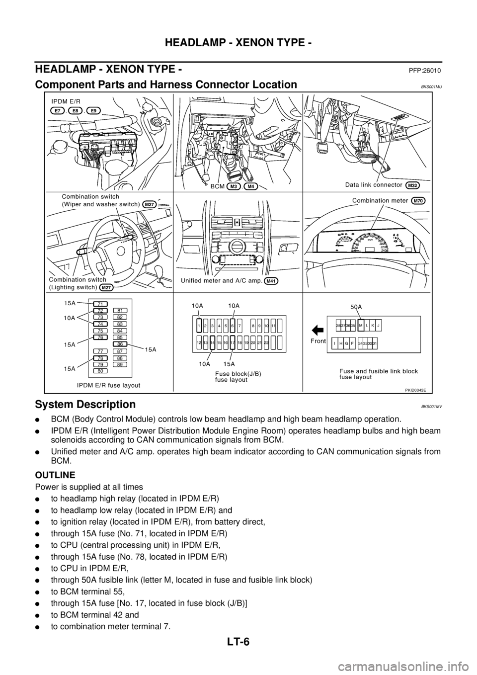
Component Parts and Harness Connector LocationBKS001MU
System DescriptionBKS001MV
�BCM (Body Control Module) controls low beam headlamp and high beam headlamp operation.
�IPDM E/R (Intelligent Power Distribution Module Engine Room) operates headlamp bulbs and high beam
solenoids according to CAN communication signals from BCM.
�Unified meter and A/C amp. operates high beam indicator according to CAN communication signals from
BCM.
OUTLINE
Power is supplied at all times
�to headlamp high relay (located in IPDM E/R)
�to headlamp low relay (located in IPDM E/R) and
�to ignition relay (located in IPDM E/R), from battery direct,
�through 15A fuse (No. 71, located in IPDM E/R)
�to CPU (central processing unit) in IPDM E/R,
�through 15A fuse (No. 78, located in IPDM E/R)
�to CPU in IPDM E/R,
�through 50A fusible link (letter M, located in fuse and fusible link block)
�to BCM terminal 55,
�through 15A fuse [No. 17, located in fuse block (J/B)]
�to BCM terminal 42 and
�to combination meter terminal 7.
PKID0043E
Page 2721 of 3502
HEADLAMP - XENON TYPE -
LT-33
C
D
E
F
G
H
I
J
L
MA
B
LT
Aiming AdjustmentBKS001NF
PREPARATION BEFORE ADJUSTING
For Details, Refer To the Regulations In Your Own Country.
Before performing aiming adjustment, check the following.
1. Keep all tires inflated to correct pressures.
2. Place vehicle on level ground.
3. Set that there is no-load in vehicle other than the driver (or equivalent weight placed in driver's position).
Coolant, engine oil filled up to correct level and full fuel tank.
LOW BEAM AND HIGH BEAM
1. Turn headlamp low beam ON.
2. Use adjustment screws to perform aiming adjustment.
PKIC9406E
Page 2723 of 3502

HEADLAMP - XENON TYPE -
LT-35
C
D
E
F
G
H
I
J
L
MA
B
LT
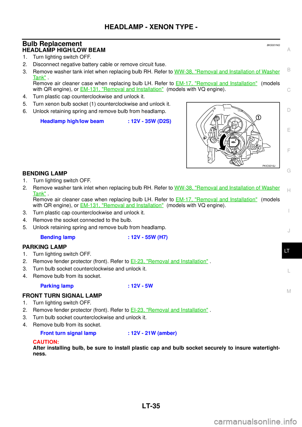
Bulb ReplacementBKS001NG
HEADLAMP HIGH/LOW BEAM
1. Turn lighting switch OFF.
2. Disconnect negative battery cable or remove circuit fuse.
3. Remove washer tank inlet when replacing bulb RH. Refer to WW-38, "
Removal and Installation of Washer
Ta n k" .
Remove air cleaner case when replacing bulb LH. Refer to EM-17, "
Removal and Installation" (models
with QR engine), or EM-131, "
Removal and Installation" (models with VQ engine).
4. Turn plastic cap counterclockwise and unlock it.
5. Turn xenon bulb socket (1) counterclockwise and unlock it.
6. Unlock retaining spring and remove bulb from headlamp.
BENDING LAMP
1. Turn lighting switch OFF.
2. Remove washer tank inlet when replacing bulb RH. Refer to WW-38, "
Removal and Installation of Washer
Ta n k" .
Remove air cleaner case when replacing bulb LH. Refer to EM-17, "
Removal and Installation" (models
with QR engine), or EM-131, "
Removal and Installation" (models with VQ engine).
3. Turn plastic cap counterclockwise and unlock it.
4. Remove the socket connected to the bulb.
5. Unlock retaining spring and remove bulb from headlamp.
PARKING LAMP
1. Turn lighting switch OFF.
2. Remove fender protector (front). Refer to EI-23, "
Removal and Installation" .
3. Turn bulb socket counterclockwise and unlock it.
4. Remove bulb from its socket.
FRONT TURN SIGNAL LAMP
1. Turn lighting switch OFF.
2. Remove fender protector (front). Refer to EI-23, "
Removal and Installation" .
3. Turn bulb socket counterclockwise and unlock it.
4. Remove bulb from its socket.
CAUTION:
After installing bulb, be sure to install plastic cap and bulb socket securely to insure watertight-
ness.Headlamp high/low beam : 12V - 35W (D2S)
PKIC9216J
Bending lamp : 12V - 55W (H7)
Parking lamp : 12V - 5W
Front turn signal lamp : 12V - 21W (amber)
Page 2726 of 3502

LT-38
HEADLAMP - HALOGEN TYPE -
HEADLAMP - HALOGEN TYPE -PFP:26010
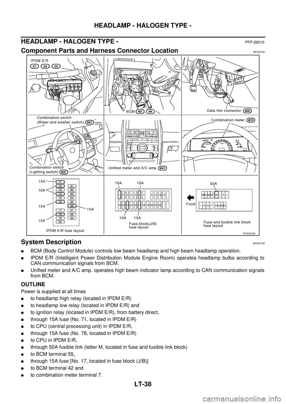
Component Parts and Harness Connector LocationBKS001NJ
System DescriptionBKS001NK
�BCM (Body Control Module) controls low beam headlamp and high beam headlamp operation.
�IPDM E/R (Intelligent Power Distribution Module Engine Room) operates headlamp bulbs according to
CAN communication signals from BCM.
�Unified meter and A/C amp. operates high beam indicator lamp according to CAN communication signals
from BCM.
OUTLINE
Power is supplied at all times
�to headlamp high relay (located in IPDM E/R)
�to headlamp low relay (located in IPDM E/R) and
�to ignition relay (located in IPDM E/R), from battery direct,
�through 15A fuse (No. 71, located in IPDM E/R)
�to CPU (central processing unit) in IPDM E/R,
�through 15A fuse (No. 78, located in IPDM E/R)
�to CPU in IPDM E/R,
�through 50A fusible link (letter M, located in fuse and fusible link block)
�to BCM terminal 55,
�through 15A fuse [No. 17, located in fuse block (J/B)]
�to BCM terminal 42 and
�to combination meter terminal 7.
PKID0043E