2003 NISSAN ALMERA N16 blower
[x] Cancel search: blowerPage 2937 of 3189
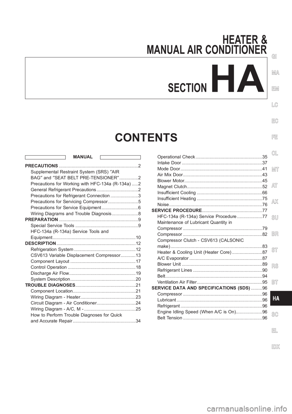
HEATER &
MANUAL AIR CONDITIONER
SECTION
HA
CONTENTS
MANUAL
PRECAUTIONS<0011001100110011001100110011001100110011001100110011001100110011001100110011001100110011001100110011001100110011001100110011001100110011001100110011001100110011001100110011001100110011001100110011001100
11001100110011001100110011001100110011001100110011[2
Supplemental Restraint System (SRS)″AIR
BAG″and″SEAT BELT PRE-TENSIONER″...............2
Precautions for Working with HFC-134a (R-134a) .....2
General Refrigerant Precautions .................................2
Precautions for Refrigerant Connection ......................3
Precautions for Servicing Compressor ........................5
Precautions for Service Equipment .............................6
Wiring Diagrams and Trouble Diagnosis .....................8
PREPARATION<0011001100110011001100110011001100110011001100110011001100110011001100110011001100110011001100110011001100110011001100110011001100110011001100110011001100110011001100110011001100110011001100110011001100
11001100110011001100110011001100110011001100110011[9
Special Service Tools ..................................................9
HFC-134a (R-134a) Service Tools and
Equipment <0011001100110011001100110011001100110011001100110011001100110011001100110011001100110011001100110011001100110011001100110011001100110011001100110011001100110011001100110011001100110011001100110011001100
11001100110011[............10
DESCRIPTION<0011001100110011001100110011001100110011001100110011001100110011001100110011001100110011001100110011001100110011001100110011001100110011001100110011001100110011001100110011001100110011001100110011001100
11001100110011001100110011001100110011001100110011[12
Refrigeration System .................................................12
CSV613 Variable Displacement Compressor............13
Component Layout ....................................................17
Control Operation ......................................................18
Discharge Air Flow.....................................................19
System Description ....................................................20
TROUBLE DIAGNOSES................................................21
Component Location..................................................21
Wiring Diagram - Heater............................................23
Circuit Diagram - Air Conditioner...............................24
Wiring Diagram - A/C, M - .........................................25
How to Perform Trouble Diagnoses for Quick
and Accurate Repair ..................................................34Operational Check .....................................................35
Intake Door <0011001100110011001100110011001100110011001100110011001100110011001100110011001100110011001100110011001100110011001100110011001100110011001100110011001100110011001100110011001100110011001100110011001100
1100110011[...........37
Mode Door <0011001100110011001100110011001100110011001100110011001100110011001100110011001100110011001100110011001100110011001100110011001100110011001100110011001100110011001100110011001100110011001100110011001100
110011001100110011[..........41
Air Mix Door <0011001100110011001100110011001100110011001100110011001100110011001100110011001100110011001100110011001100110011001100110011001100110011001100110011001100110011001100110011001100110011001100110011001100
1100110011[..........43
Blower Motor<0011001100110011001100110011001100110011001100110011001100110011001100110011001100110011001100110011001100110011001100110011001100110011001100110011001100110011001100110011001100110011001100110011001100
110011[..........45
Magnet Clutch<0011001100110011001100110011001100110011001100110011001100110011001100110011001100110011001100110011001100110011001100110011001100110011001100110011001100110011001100110011001100110011001100110011001100
11[.........52
Insufficient Cooling ....................................................66
Insufficient Heating ....................................................75
Noise <0011001100110011001100110011001100110011001100110011001100110011001100110011001100110011001100110011001100110011001100110011001100110011001100110011001100110011001100110011001100110011001100110011001100
110011001100110011001100110011[................76
SERVICE PROCEDURE................................................77
HFC-134a (R-134a) Service Procedure ....................77
Maintenance of Lubricant Quantity in
Compressor <0011001100110011001100110011001100110011001100110011001100110011001100110011001100110011001100110011001100110011001100110011001100110011001100110011001100110011001100110011001100110011001100110011001100
1100110011[..........79
Compressor <0011001100110011001100110011001100110011001100110011001100110011001100110011001100110011001100110011001100110011001100110011001100110011001100110011001100110011001100110011001100110011001100110011001100
1100110011[..........82
Compressor Clutch - CSV613 (CALSONIC
make) <0011001100110011001100110011001100110011001100110011001100110011001100110011001100110011001100110011001100110011001100110011001100110011001100110011001100110011001100110011001100110011001100110011001100
110011001100110011001100110011[...............83
Heater & Cooling Unit (Heater Core) ........................87
A/C Evaporator ..........................................................87
Blower Unit <0011001100110011001100110011001100110011001100110011001100110011001100110011001100110011001100110011001100110011001100110011001100110011001100110011001100110011001100110011001100110011001100110011001100
1100110011[...........89
Refrigerant Lines .......................................................90
Belt <0011001100110011001100110011001100110011001100110011001100110011001100110011001100110011001100110011001100110011001100110011001100110011001100110011001100110011001100110011001100110011001100110011001100
1100110011001100110011001100110011[..................94
Ventilation Air Filter ....................................................95
SERVICE DATA AND SPECIFICATIONS (SDS).........96
Compressor <0011001100110011001100110011001100110011001100110011001100110011001100110011001100110011001100110011001100110011001100110011001100110011001100110011001100110011001100110011001100110011001100110011001100
1100110011[..........96
Lubricant <0011001100110011001100110011001100110011001100110011001100110011001100110011001100110011001100110011001100110011001100110011001100110011001100110011001100110011001100110011001100110011001100110011001100
11001100110011[..............96
Refrigerant <0011001100110011001100110011001100110011001100110011001100110011001100110011001100110011001100110011001100110011001100110011001100110011001100110011001100110011001100110011001100110011001100110011001100
110011[.............96
Engine Idling Speed (When A/C is On).....................96
Belt Tension <0011001100110011001100110011001100110011001100110011001100110011001100110011001100110011001100110011001100110011001100110011001100110011001100110011001100110011001100110011001100110011001100110011001100
110011[...........96
GI
MA
EM
LC
EC
FE
CL
MT
AT
AX
SU
BR
ST
RS
BT
SC
EL
IDX
Page 2970 of 3189
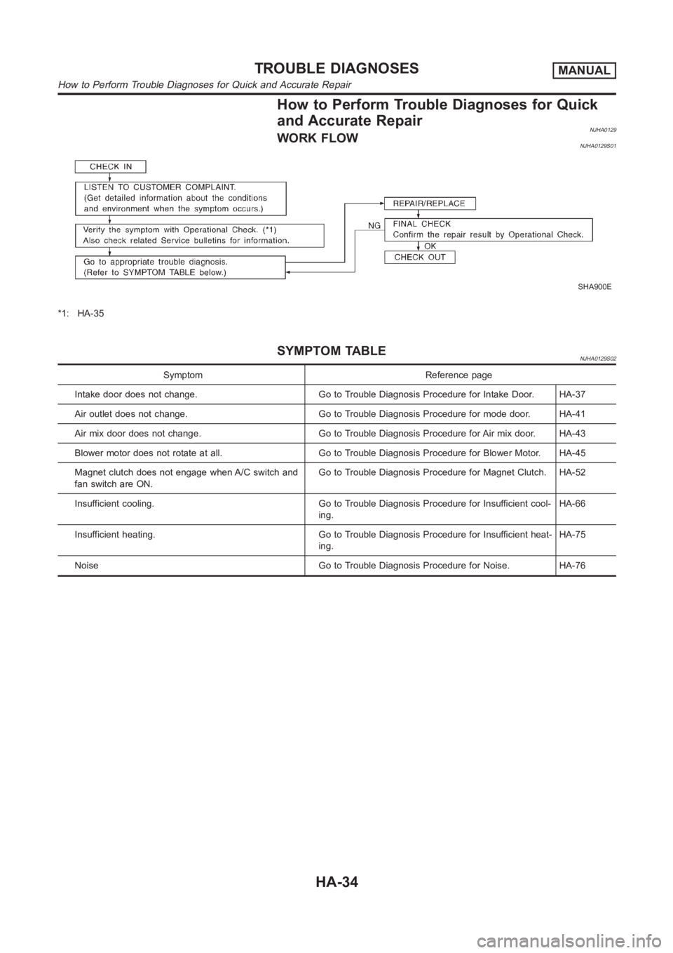
How to Perform Trouble Diagnoses for Quick
and Accurate Repair
NJHA0129WORK FLOWNJHA0129S01
SHA900E
*1: HA-35
SYMPTOM TABLENJHA0129S02
Symptom Reference page
Intake door does not change. Go to Trouble Diagnosis Procedure for Intake Door. HA-37
Air outlet does not change. Go to Trouble Diagnosis Procedure for mode door. HA-41
Air mix door does not change. Go to Trouble Diagnosis Procedure for Air mix door. HA-43
Blower motor does not rotate at all. Go to Trouble Diagnosis Procedure for Blower Motor. HA-45
Magnet clutch does not engage when A/C switch and
fan switch are ON.Go to Trouble Diagnosis Procedure for Magnet Clutch. HA-52
Insufficient cooling. Go to Trouble Diagnosis Procedure for Insufficient cool-
ing.HA-66
Insufficient heating. Go to Trouble Diagnosis Procedure for Insufficientheat-
ing.HA-75
Noise Go to Trouble Diagnosis Procedure for Noise. HA-76
TROUBLE DIAGNOSESMANUAL
How to Perform Trouble Diagnoses for Quick and Accurate Repair
HA-34
Page 2971 of 3189
Operational Check=NJHA0130The purpose of the operational check is to confirm that the system
operates properly.
CONDITIONS:NJHA0130S01Engine running and at usual operating temperature.
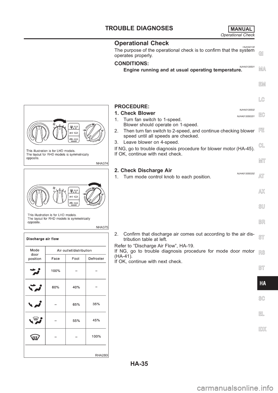
NHA374
PROCEDURE:NJHA0130S021. Check BlowerNJHA0130S02011. Turn fan switch to 1-speed.
Blower should operate on 1-speed.
2. Then turn fan switch to 2-speed, and continue checking blower
speed until all speeds are checked.
3. Leave blower on 4-speed.
If NG, go to trouble diagnosis procedure for blower motor (HA-45).
If OK, continue with next check.
NHA375
2. Check Discharge AirNJHA0130S02021. Turn mode control knob to each position.
RHA280I
2. Confirm that discharge air comes out according to the air dis-
tribution table at left.
Refer to “Discharge Air Flow”, HA-19.
If NG, go to trouble diagnosis procedure for mode door motor
(HA-41).
If OK, continue with next check.
GI
MA
EM
LC
EC
FE
CL
MT
AT
AX
SU
BR
ST
RS
BT
SC
EL
IDX
TROUBLE DIAGNOSESMANUAL
Operational Check
HA-35
Page 2981 of 3189
Blower Motor
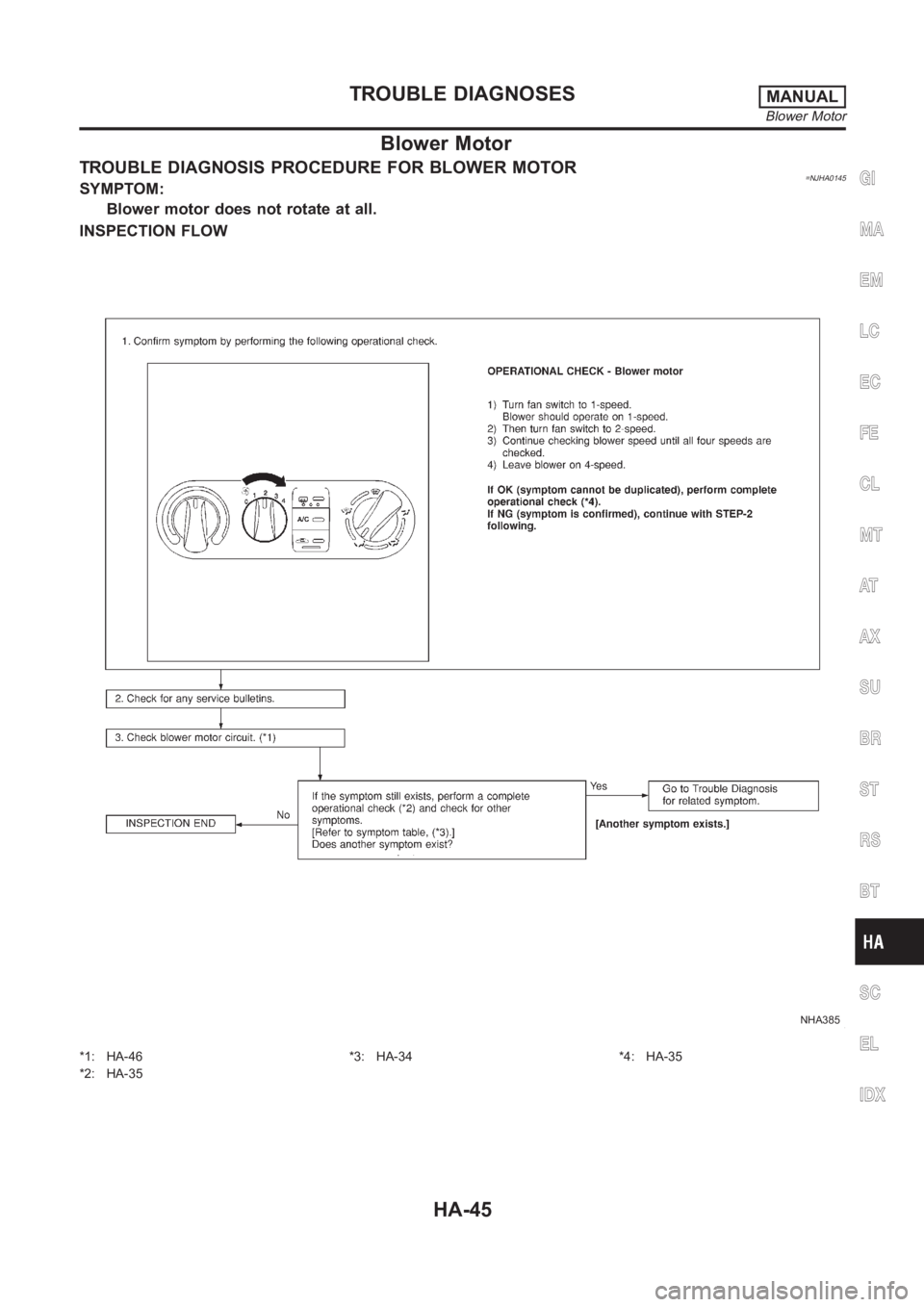
TROUBLE DIAGNOSIS PROCEDURE FOR BLOWER MOTOR=NJHA0145SYMPTOM:
Blower motor does not rotate at all.
INSPECTION FLOW
NHA385
*1: HA-46
*2: HA-35*3: HA-34 *4: HA-35
GI
MA
EM
LC
EC
FE
CL
MT
AT
AX
SU
BR
ST
RS
BT
SC
EL
IDX
TROUBLE DIAGNOSESMANUAL
Blower Motor
HA-45
Page 2982 of 3189
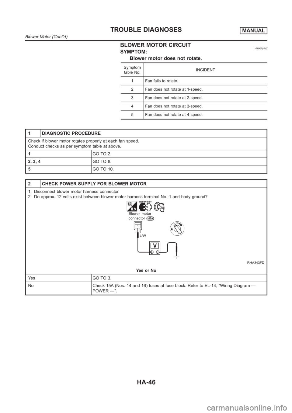
BLOWER MOTOR CIRCUIT=NJHA0147SYMPTOM:
Blower motor does not rotate.
Symptom
table No.INCIDENT
1 Fan fails to rotate.
2 Fan does not rotate at 1-speed.
3 Fan does not rotate at 2-speed.
4 Fan does not rotate at 3-speed.
5 Fan does not rotate at 4-speed.
1 DIAGNOSTIC PROCEDURE
Check if blower motor rotates properly at each fan speed.
Conduct checks as per symptom table at above.
1GO TO 2.
2, 3, 4GO TO 8.
5GO TO 10.
2 CHECK POWER SUPPLY FOR BLOWER MOTOR
1. Disconnect blower motor harness connector.
2. Do approx. 12 volts exist between blower motor harness terminal No. 1 andbody ground?
RHA343FD
YesorNo
Ye s G O T O 3 .
No Check 15A (Nos. 14 and 16) fuses at fuse block. Refer to EL-14, “Wiring Diagram —
POWER —”.
TROUBLE DIAGNOSESMANUAL
Blower Motor (Cont’d)
HA-46
Page 2983 of 3189
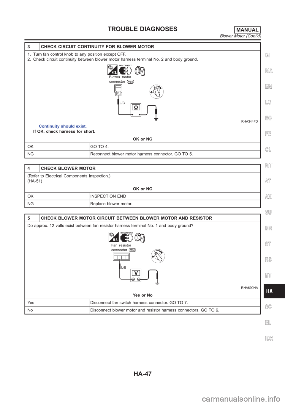
3 CHECK CIRCUIT CONTINUITY FOR BLOWER MOTOR
1. Turn fan control knob to any position except OFF.
2. Check circuit continuity between blower motor harness terminal No. 2 and body ground.
RHA344FD
Continuity should exist.
If OK, check harness for short.
OK or NG
OK GO TO 4.
NG Reconnect blower motor harness connector. GO TO 5.
4 CHECK BLOWER MOTOR
(Refer to Electrical Components Inspection.)
(HA-51)
OK or NG
OK INSPECTION END
NG Replace blower motor.
5 CHECK BLOWER MOTOR CIRCUIT BETWEEN BLOWER MOTOR AND RESISTOR
Do approx. 12 volts exist between fan resistor harness terminal No. 1 and body ground?
RHA699HA
YesorNo
Yes Disconnect fan switch harness connector. GO TO 7.
No Disconnect blower motor and resistor harness connectors. GO TO 6.
GI
MA
EM
LC
EC
FE
CL
MT
AT
AX
SU
BR
ST
RS
BT
SC
EL
IDX
TROUBLE DIAGNOSESMANUAL
Blower Motor (Cont’d)
HA-47
Page 2984 of 3189
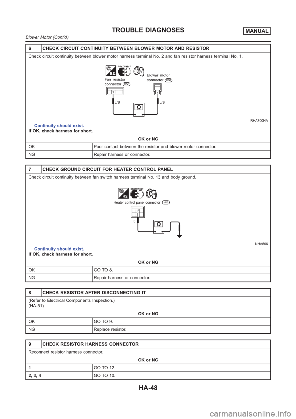
6 CHECK CIRCUIT CONTINUITY BETWEEN BLOWER MOTOR AND RESISTOR
Check circuit continuity between blower motor harness terminal No. 2 and fan resistor harness terminal No. 1.
RHA700HA
Continuity should exist.
If OK, check harness for short.
OK or NG
OK Poor contact between the resistor and blower motor connector.
NG Repair harness or connector.
7 CHECK GROUND CIRCUIT FOR HEATER CONTROL PANEL
Check circuit continuity between fan switch harness terminal No. 13 and body ground.
NHA506
Continuity should exist.
If OK, check harness for short.
OK or NG
OK GO TO 8.
NG Repair harness or connector.
8 CHECK RESISTOR AFTER DISCONNECTING IT
(Refer to Electrical Components Inspection.)
(HA-51)
OK or NG
OK GO TO 9.
NG Replace resistor.
9 CHECK RESISTOR HARNESS CONNECTOR
Reconnect resistor harness connector.
OK or NG
1GO TO 12.
2, 3, 4GO TO 10.
TROUBLE DIAGNOSESMANUAL
Blower Motor (Cont’d)
HA-48
Page 2985 of 3189
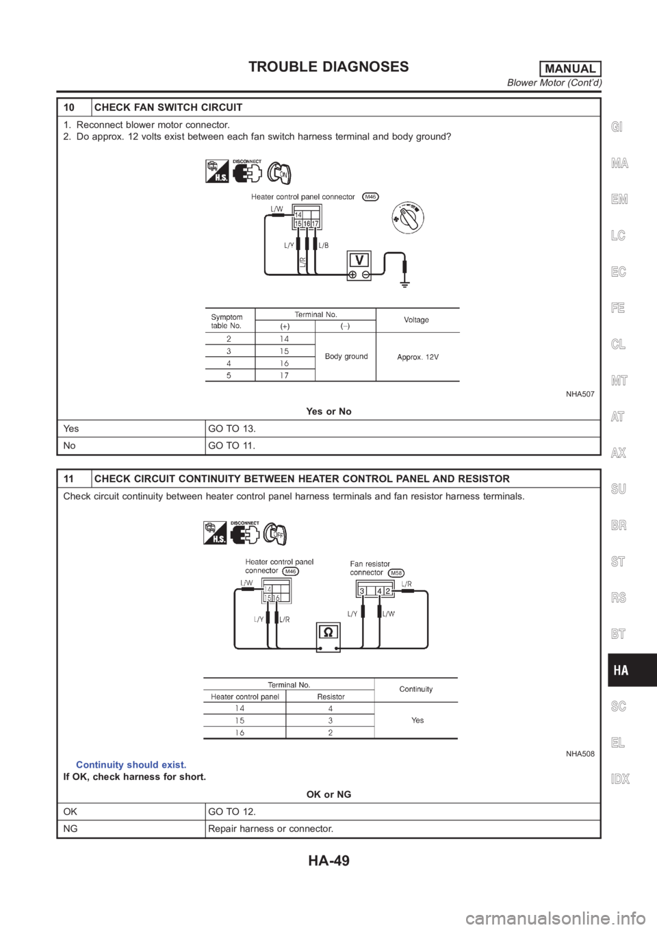
10 CHECK FAN SWITCH CIRCUIT
1. Reconnect blower motor connector.
2. Do approx. 12 volts exist between each fan switch harness terminal and body ground?
NHA507
YesorNo
Yes GO TO 13.
No GO TO 11.
11 CHECK CIRCUIT CONTINUITY BETWEEN HEATER CONTROL PANEL AND RESISTOR
Check circuit continuity between heater control panel harness terminalsand fan resistor harness terminals.
NHA508
Continuity should exist.
If OK, check harness for short.
OK or NG
OK GO TO 12.
NG Repair harness or connector.
GI
MA
EM
LC
EC
FE
CL
MT
AT
AX
SU
BR
ST
RS
BT
SC
EL
IDX
TROUBLE DIAGNOSESMANUAL
Blower Motor (Cont’d)
HA-49