Page 2021 of 3189

TROUBLE DIAGNOSIS
ATC-41
C
D
E
F
G
H
I
K
L
MA
B
AT C
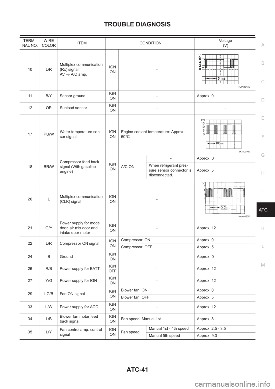
10 L/RMultiplex communication
(Rx) signal
AV → A/C amp.IGN
ON-
11 B/Y Sensor ground IGN
ON-Approx. 0
12 OR Sunload sensorIGN
ON--
17 PU/WWater temperature sen-
sor signalIGN
ONEngine coolant temperature: Approx.
60°C
18 BR/WCompressor feed back
signal (With gasoline
engine)IGN
ONA/C ON-Approx. 0
When refrigerant pres-
sure sensor connector is
disconnected.Approx. 5
20 LMultiplex communication
(CLK) signalIGN
ON-
21 G/YPower supply for mode
door, air mix door and
intake door motorIGN
ON-Approx. 12
22 L/R Compressor ON signalIGN
ONCompressor: ON Approx. 0
Compressor: OFF Approx. 5
24 B GroundIGN
ON-Approx. 0
26 R/B Power supply for BATTIGN
OFF-Approx. 12
27 Y/G Power supply for IGNIGN
ON-Approx. 12
29 LG/B Fan ON signalIGN
ONBlower fan: ON Approx. 0
Blower fan: OFF Approx. 5
33 L/W Power supply for ACCIGN
ON-Approx. 12
34 L/BBlower fan motor feed
back signalIGN
ONFan speed: Manual 1st Approx. 8
35 L/YFan control amp. control
signalIGN
ONFan speed:Manual 1st - 4th speed Approx. 2.5 - 3.5
Manual 5th speed Approx. 9.0 TERMI-
NAL NO.WIRE
COLORITEM CONDITIONVo lta g e
(V)
RJIA0213E
SKIA0056J
HAK0363D
Page 2022 of 3189
ATC-42
TROUBLE DIAGNOSIS
Self-diagnosis Function
EJS001ZH
DESCRIPTION
The self-diagnostic system diagnoses sensors, door motors, blower motor, etc. by system line. Refer to appli-
cable sections (items) for details. Shifting from usual control to the self-diagnostic system is accomplished by
starting the engine (turning the ignition switch from OFF to ON) and pressing OFF switch for at least 5 sec-
onds. The “OFF” switch must be pressed within 10 seconds after starting the engine (ignition switch is turned
ON). This system will be canceled by either pressing A/C switch or turning the ignition switch OFF. Shifting
from one step to another is accomplished by means of turning temperature dial, as required.
Additionally shifting from STEP 6 to AUXILIARY MECHANISM is accomplished by means of pushing (fan)
UP switch.
RJIA1681E
Page 2026 of 3189

ATC-46
TROUBLE DIAGNOSIS
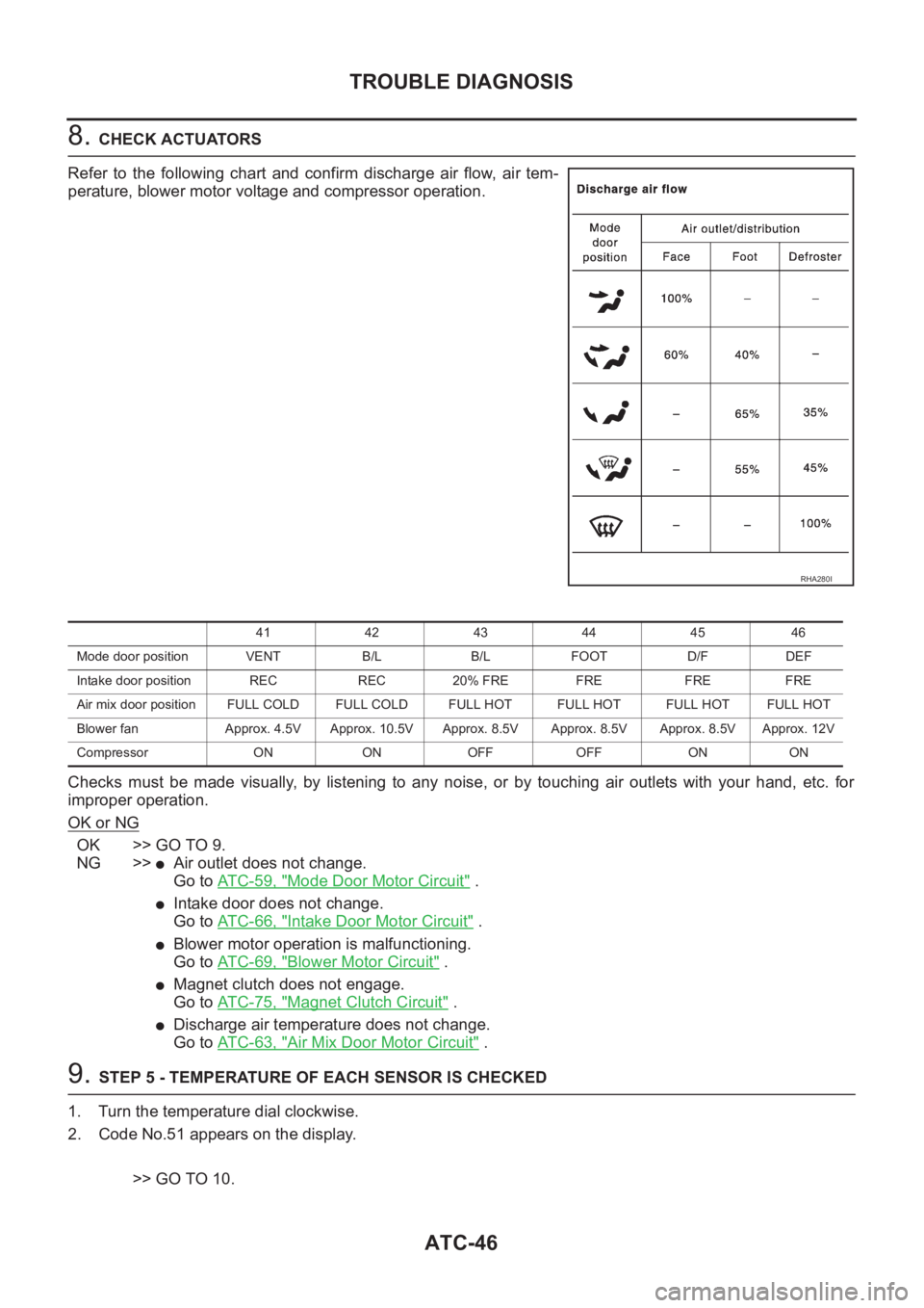
8. CHECK ACTUATORS
Refer to the following chart and confirm discharge air flow, air tem-
perature, blower motor voltage and compressor operation.
Checks must be made visually, by listening to any noise, or by touching air outlets with your hand, etc. for
improper operation.
OK or NG
OK >> GO TO 9.
NG >>
●Air outlet does not change.
Go to AT C - 5 9 , "
Mode Door Motor Circuit" .
●Intake door does not change.
Go to AT C - 6 6 , "
Intake Door Motor Circuit" .
●Blower motor operation is malfunctioning.
Go to AT C - 6 9 , "
Blower Motor Circuit" .
●Magnet clutch does not engage.
Go to AT C - 7 5 , "
Magnet Clutch Circuit" .
●Discharge air temperature does not change.
Go to AT C - 6 3 , "
Air Mix Door Motor Circuit" .
9. STEP 5 - TEMPERATURE OF EACH SENSOR IS CHECKED
1. Turn the temperature dial clockwise.
2. Code No.51 appears on the display.
>> GO TO 10.
RHA280I
41 42 43 44 45 46
Mode door position VENT B/L B/L FOOT D/F DEF
Intake door position REC REC 20% FRE FRE FRE FRE
Air mix door position FULL COLD FULL COLD FULL HOT FULL HOT FULL HOTFULL HOT
Blower fan Approx. 4.5V Approx. 10.5V Approx. 8.5V Approx. 8.5V Approx. 8.5V Approx. 12V
Compressor ON ON OFF OFF ON ON
Page 2031 of 3189
TROUBLE DIAGNOSIS
ATC-51
C
D
E
F
G
H
I
K
L
MA
B
AT C
Operational CheckEJS001ZI
The purpose of the operational check is to confirm that the system operates properly.
CHECKING MEMORY FUNCTION
1. Set the temperature 90°F or 32°C.
2. Press OFF switch.
3. Turn the ignition switch OFF.
4. Turn the ignition switch ON.
5. Press the AUTO switch.
6. Confirm that the set temperature remains at previous tempera-
ture.
7. Press OFF switch.
If NG, go to ATC-99, "
Memory Function" .
If OK, continue with next check.
CHECKING BLOWER
1. Press fan switch (up side) one time. Blower should operate on
low speed.The fan symbol should have one blade lit .
2. Press fan switch (up side) one more time, and continue check-
ing blower speed and fan symbol until all speeds are checked.
3. Leave blower on MAX speed.
If NG, go to ATC-69, "
Blower Motor Circuit" .
If OK, continue with next check.Conditions :Engine running and at usual operating temperature
RJIA1683E
RJIA1684E
Page 2033 of 3189

TROUBLE DIAGNOSIS
ATC-53
C
D
E
F
G
H
I
K
L
MA
B
AT C
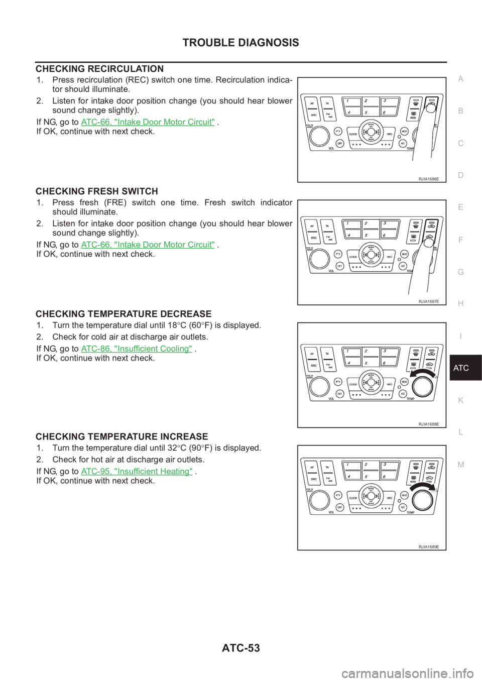
CHECKING RECIRCULATION
1. Press recirculation (REC) switch one time. Recirculation indica-
tor should illuminate.
2. Listen for intake door position change (you should hear blower
sound change slightly).
If NG, go to ATC-66, "
Intake Door Motor Circuit" .
If OK, continue with next check.
CHECKING FRESH SWITCH
1. Press fresh (FRE) switch one time. Fresh switch indicator
should illuminate.
2. Listen for intake door position change (you should hear blower
sound change slightly).
If NG, go to ATC-66, "
Intake Door Motor Circuit" .
If OK, continue with next check.
CHECKING TEMPERATURE DECREASE
1. Turn the temperature dial until 18°C (60°F) is displayed.
2. Check for cold air at discharge air outlets.
If NG, go to ATC-86, "
Insufficient Cooling" .
If OK, continue with next check.
CHECKING TEMPERATURE INCREASE
1. Turn the temperature dial until 32°C (90°F) is displayed.
2. Check for hot air at discharge air outlets.
If NG, go to ATC-95, "
Insufficient Heating" .
If OK, continue with next check.
RJIA1686E
RJIA1687E
RJIA1688E
RJIA1689E
Page 2034 of 3189
ATC-54
TROUBLE DIAGNOSIS
CHECKING AUTO MODE
1. Press temperature dial.
2. Display should indicate AUTO (not ECON).
●Confirm that the compressor clutch engages (audio or visual
inspection). (Discharge air and blower speed will depend on
ambient, in-vehicle, and set temperatures.)
If NG, go to AT C - 5 5 , "
Power Supply and Ground Circuit for Auto
Amp." , then if necessary, go to AT C - 7 5 , "Magnet Clutch Circuit" .
If all operational check are OK (symptom can not be duplicated), go
to Incident Simulation Tests in GI-22, "How to Perform Efficient Diag-
nosis for an Electrical Incident" and perform tests as outlined to sim-
ulate driving conditions environment. If symptom appears, refer to
AT C - 2 9 , "
SYMPTOM TABLE" and perform applicable trouble diag-
nosis procedures.
RJIA1690E
Page 2035 of 3189

TROUBLE DIAGNOSIS
ATC-55
C
D
E
F
G
H
I
K
L
MA
B
AT C
Power Supply and Ground Circuit for Auto Amp.EJS001ZJ
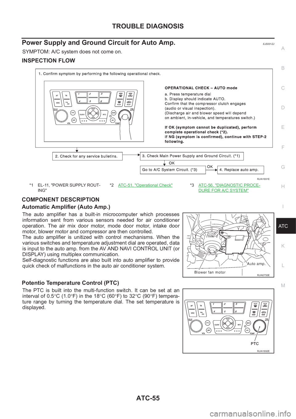
SYMPTOM: A/C system does not come on.
INSPECTION FLOW
COMPONENT DESCRIPTION
Automatic Amplifier (Auto Amp.)
The auto amplifier has a built-in microcomputer which processes
information sent from various sensors needed for air conditioner
operation. The air mix door motor, mode door motor, intake door
motor, blower motor and compressor are then controlled.
The auto amplifier is unitized with control mechanisms. When the
various switches and temperature adjustment dial are operated, data
is input to the auto amp. from the AV AND NAVI CONTROL UNIT (or
DISPLAY) using multiplex communication.
Self-diagnostic functions are also built into auto amplifier to provide
quick check of malfunctions in the auto air conditioner system.
Potentio Temperature Control (PTC)
The PTC is built into the multi-function switch. It can be set at an
interval of 0.5°C (1.0°F) in the 18°C (60°F) to 32°C (90°F) tempera-
ture range by turning the temperature dial. The set temperature is
displayed.
*1 EL-11, "POWER SUPPLY ROUT-
ING"*2AT C - 5 1 , "Operational Check"*3AT C - 5 6 , "DIAGNOSTIC PROCE-
DURE FOR A/C SYSTEM"
RJIA1691E
RJIA0750E
RJIA1692E
Page 2049 of 3189
TROUBLE DIAGNOSIS
ATC-69
C
D
E
F
G
H
I
K
L
MA
B
AT C
Blower Motor CircuitEJS001ZO
SYMPTOM:
●Blower motor operation is malfunctioning.
●Blower motor operation is malfunctioning under out of starting fan speed control.
INSPECTION FLOW
RJIA1696E