Page 2986 of 3189
12 CHECK CIRCUIT CONTINUITY BETWEEN HEATER CONTROL PANEL AND BLOWER MOTOR
Check circuit continuity between heater control panel harness terminal No. 17 and blower motor harness terminal No. 2.
NHA509
Continuity should exist.
If OK, check harness for short.
OK or NG
OK GO TO 13.
NG Repair harness or connector.
13 CHECK FAN SWITCH AFTER DISCONNECTING IT
(Refer to Electrical Components Inspection.)
(HA-51)
OK or NG
OK INSPECTION END
NG Replace fan switch.
TROUBLE DIAGNOSESMANUAL
Blower Motor (Cont’d)
HA-50
Page 2987 of 3189
NHA386
ELECTRICAL COMPONENTS INSPECTION=NJHA0146Fan SwitchNJHA0146S01Check continuity between terminals at each switch position.
KNOB POSITION Continuity between terminals
OFF No continuity
113—14—18
213—15—18
313—16—18
413—17—18
Blower MotorNJHA0146S02Confirm smooth rotation of the blower motor.
Ensure that there are no foreign particles inside the intake unit.
RHA706H
Blower ResistorNJHA0146S03Check resistance between terminals.
Terminal No.
Resistance
(+) (−)
4
1Approx. 1.8 - 2.2Ω
3 Approx. 0.45 - 0.55Ω
2 Approx. 0.18 - 0.22Ω
GI
MA
EM
LC
EC
FE
CL
MT
AT
AX
SU
BR
ST
RS
BT
SC
EL
IDX
TROUBLE DIAGNOSESMANUAL
Blower Motor (Cont’d)
HA-51
Page 3005 of 3189
PERFORMANCE CHART=NJHA0150Test ConditionNJHA0150S01Testing must be performed as follows:
Vehicle location: Indoors or in the shade (in a well-ventilated place)
Doors: Closed
Door window: Open
Hood: Open
TEMP.: Max. COLD
Discharge Air: Face Vent
REC switch: (Recirculation) set
FAN speed: High speed
Engine speed: Idle speed
Operate the air conditioning system for 10 minutes before taking
measurements.
Test Reading (Gasoline Engine)NJHA0150S02Recirculating-to-discharge Air Temperature TableNJHA0150S0201
Inside air (Recirculating air) at blower assembly inlet
Discharge air temperature at center venti-
lator
°C (°F) Relative humidity
%Air temperature
°C (°F)
50 - 6025 (77) 10.0 - 11.6 (50 - 53)
30 (86) 13.9 - 16.2 (57 - 61)
35 (95) 17.8 - 21.4 (64 - 71)
60 - 7025 (77) 11.6 - 13.9 (53 - 57)
30 (86) 16.2 - 18.9 (61 - 66)
35 (95) 21.4 - 24.5 (71 - 76)
GI
MA
EM
LC
EC
FE
CL
MT
AT
AX
SU
BR
ST
RS
BT
SC
EL
IDX
TROUBLE DIAGNOSESMANUAL
Insufficient Cooling (Cont’d)
HA-69
Page 3006 of 3189

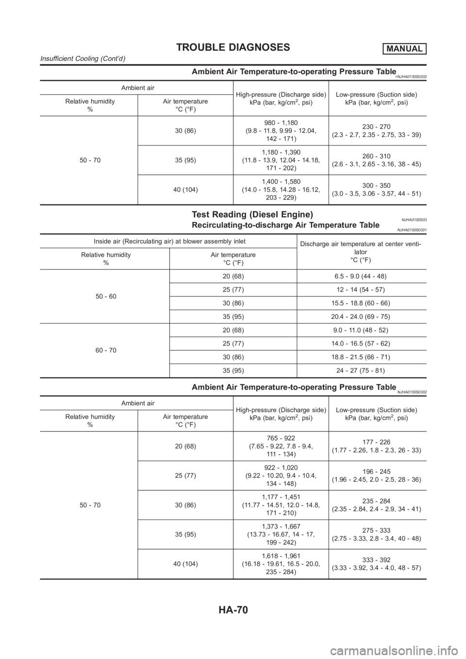
Ambient Air Temperature-to-operating Pressure Table=NJHA0150S0202
Ambient air
High-pressure (Discharge side)
kPa (bar, kg/cm
2, psi)Low-pressure (Suction side)
kPa (bar, kg/cm2, psi) Relative humidity
%Air temperature
°C (°F)
50 - 7030 (86)980 - 1,180
(9.8 - 11.8, 9.99 - 12.04,
142 - 171)230 - 270
(2.3 - 2.7, 2.35 - 2.75, 33 - 39)
35 (95)1,180 - 1,390
(11.8 - 13.9, 12.04 - 14.18,
171 - 202)260 - 310
(2.6 - 3.1, 2.65 - 3.16, 38 - 45)
40 (104)1,400 - 1,580
(14.0 - 15.8, 14.28 - 16.12,
203 - 229)300 - 350
(3.0 - 3.5, 3.06 - 3.57, 44 - 51)
Test Reading (Diesel Engine)NJHA0150S03Recirculating-to-discharge Air Temperature TableNJHA0150S0301
Inside air (Recirculating air) at blower assembly inlet
Discharge air temperature at center venti-
lator
°C (°F) Relative humidity
%Air temperature
°C (°F)
50 - 6020 (68) 6.5 - 9.0 (44 - 48)
25 (77) 12 - 14 (54 - 57)
30 (86) 15.5 - 18.8 (60 - 66)
35 (95) 20.4 - 24.0 (69 - 75)
60 - 7020 (68) 9.0 - 11.0 (48 - 52)
25 (77) 14.0 - 16.5 (57 - 62)
30 (86) 18.8 - 21.5 (66 - 71)
35 (95) 24 - 27 (75 - 81)
Ambient Air Temperature-to-operating Pressure TableNJHA0150S0302
Ambient air
High-pressure (Discharge side)
kPa (bar, kg/cm
2, psi)Low-pressure (Suction side)
kPa (bar, kg/cm2, psi) Relative humidity
%Air temperature
°C (°F)
50 - 7020 (68)765 - 922
(7.65 - 9.22, 7.8 - 9.4,
111 - 134)177 - 226
(1.77 - 2.26, 1.8 - 2.3, 26 - 33)
25 (77)922 - 1,020
(9.22 - 10.20, 9.4 - 10.4,
134 - 148)196 - 245
(1.96 - 2.45, 2.0 - 2.5, 28 - 36)
30 (86)1,177 - 1,451
(11.77 - 14.51, 12.0 - 14.8,
171 - 210)235 - 284
(2.35 - 2.84, 2.4 - 2.9, 34 - 41)
35 (95)1,373 - 1,667
(13.73 - 16.67, 14 - 17,
199 - 242)275 - 333
(2.75 - 3.33, 2.8 - 3.4, 40 - 48)
40 (104)1,618 - 1,961
(16.18 - 19.61, 16.5 - 20.0,
235 - 284)333 - 392
(3.33 - 3.92, 3.4 - 4.0, 48 - 57)
TROUBLE DIAGNOSESMANUAL
Insufficient Cooling (Cont’d)
HA-70
Page 3015 of 3189

Maintenance of Lubricant Quantity in
Compressor
NJHA0160The lubricant in the compressor circulates through the system with
the refrigerant. Add lubricant to compressor when replacing any
component or after a large gas leakage occurred. It is important to
maintain the specified amount.
If lubricant quantity is not maintained properly, the following mal-
functions may result:
Lack of lubricant: May lead to a seized compressor
Excessive lubricant: Inadequate cooling (thermal exchange
interference)
LUBRICANTNJHA0160S01Name: Nissan A/C System Oil Type S
Part number: KLH00-PAGS0
CHECKING AND ADJUSTINGNJHA0160S02Adjust the lubricant quantity according to the test group shown
below.
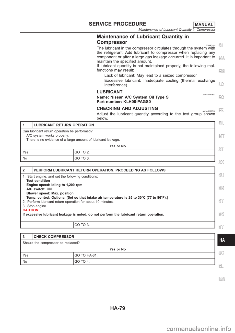
1 LUBRICANT RETURN OPERATION
Can lubricant return operation be performed?
A/C system works properly.
There is no evidence of a large amount of lubricant leakage.
YesorNo
Ye s G O T O 2 .
No GO TO 3.
2 PERFORM LUBRICANT RETURN OPERATION, PROCEEDING AS FOLLOWS
1. Start engine, and set the following conditions:
Test condition
Engine speed: Idling to 1,200 rpm
A/C switch: ON
Blower speed: Max. position
Temp. control: Optional [Set so that intake air temperature is 25 to 30°C (77 to 86°F).]
2. Perform lubricant return operation for about 10 minutes.
3. Stop engine.
CAUTION:
If excessive lubricant leakage is noted, do not perform the lubricant return operation.
GO TO 3.
3 CHECK COMPRESSOR
Should the compressor be replaced?
YesorNo
Yes GO TO HA-81.
No GO TO 4.
GI
MA
EM
LC
EC
FE
CL
MT
AT
AX
SU
BR
ST
RS
BT
SC
EL
IDX
SERVICE PROCEDUREMANUAL
Maintenance of Lubricant Quantity in Compressor
HA-79
Page 3023 of 3189

Heater & Cooling Unit (Heater Core)
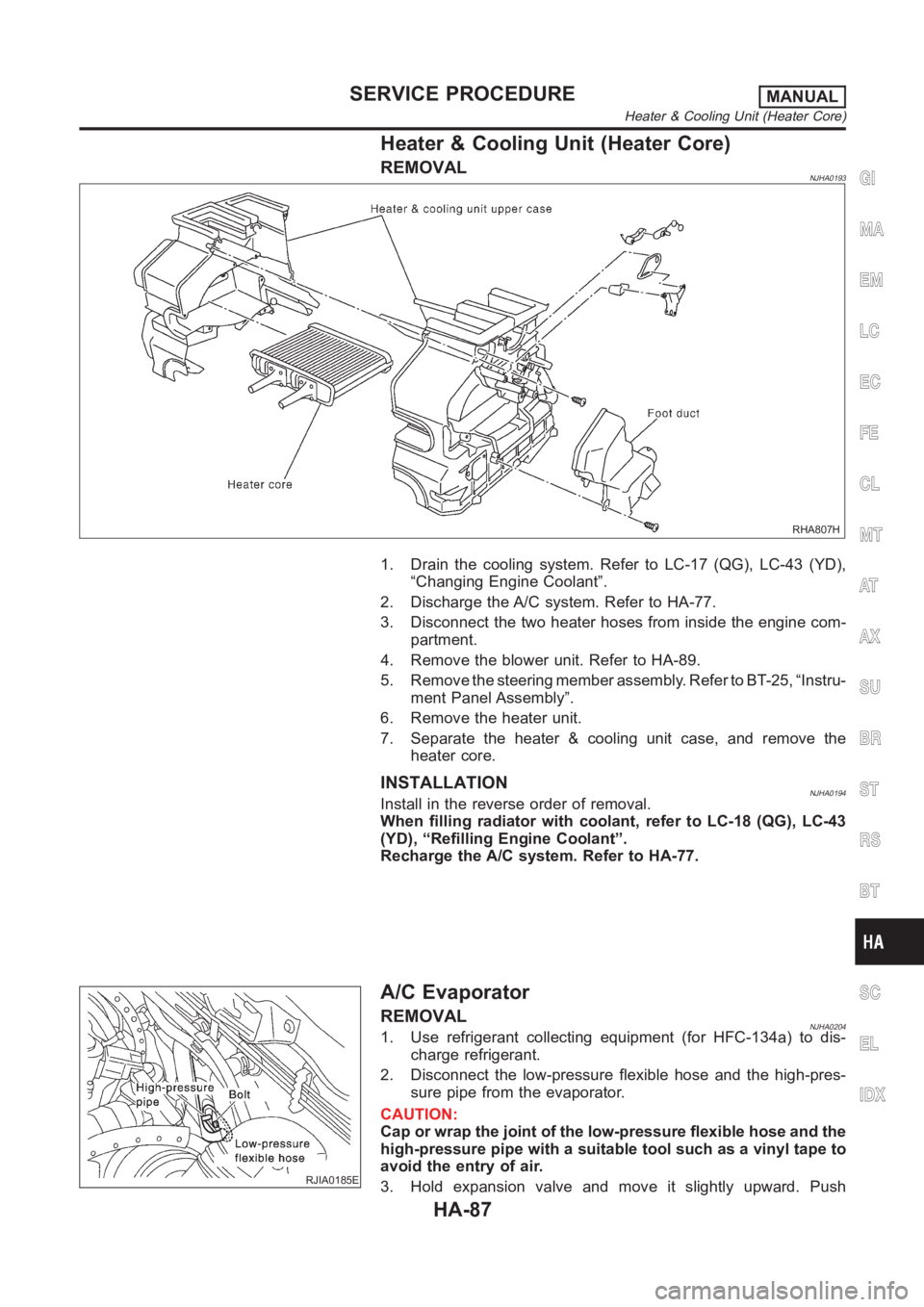
REMOVALNJHA0193
RHA807H
1. Drain the cooling system. Refer to LC-17 (QG), LC-43 (YD),
“Changing Engine Coolant”.
2. Discharge the A/C system. Refer to HA-77.
3. Disconnect the two heater hoses from inside the engine com-
partment.
4. Remove the blower unit. Refer to HA-89.
5. Remove the steering member assembly. Refer to BT-25, “Instru-
ment Panel Assembly”.
6. Remove the heater unit.
7. Separate the heater & cooling unit case, and remove the
heater core.
INSTALLATIONNJHA0194Install in the reverse order of removal.
When filling radiator with coolant, refer to LC-18 (QG), LC-43
(YD), “Refilling Engine Coolant”.
Recharge the A/C system. Refer to HA-77.
RJIA0185E
A/C Evaporator
REMOVALNJHA02041. Use refrigerant collecting equipment (for HFC-134a) to dis-
charge refrigerant.
2. Disconnect the low-pressure flexible hose and the high-pres-
sure pipe from the evaporator.
CAUTION:
Cap or wrap the joint of the low-pressure flexible hose and the
high-pressure pipe with a suitable tool such as a vinyl tape to
avoid the entry of air.
3. Hold expansion valve and move it slightly upward. Push
GI
MA
EM
LC
EC
FE
CL
MT
AT
AX
SU
BR
ST
RS
BT
SC
EL
IDX
SERVICE PROCEDUREMANUAL
Heater & Cooling Unit (Heater Core)
HA-87
Page 3025 of 3189
RJIA0842E
3. Install the lower cover, then slide evaporator to forward.
4. Install the expansion valve from engine compartment.
Expansion valve mounting bolts
Tightening torque:
2.9 - 5.0 N·m (0.30 - 0.50 kg-m, 26 - 44 in-lb)
Blower Unit
REMOVALNJHA0195
RHA676HA
1. Remove the instrument panel assembly. Refer to BT-25, “Instru-
ment Panel Assembly”.
2. Disconnect the blower motor and resistor connector.
3. Remove blower unit.
INSTALLATIONNJHA0196Install in the reverse order of removal.
GI
MA
EM
LC
EC
FE
CL
MT
AT
AX
SU
BR
ST
RS
BT
SC
EL
IDX
SERVICE PROCEDUREMANUAL
A/C Evaporator (Cont’d)
HA-89
Page 3029 of 3189

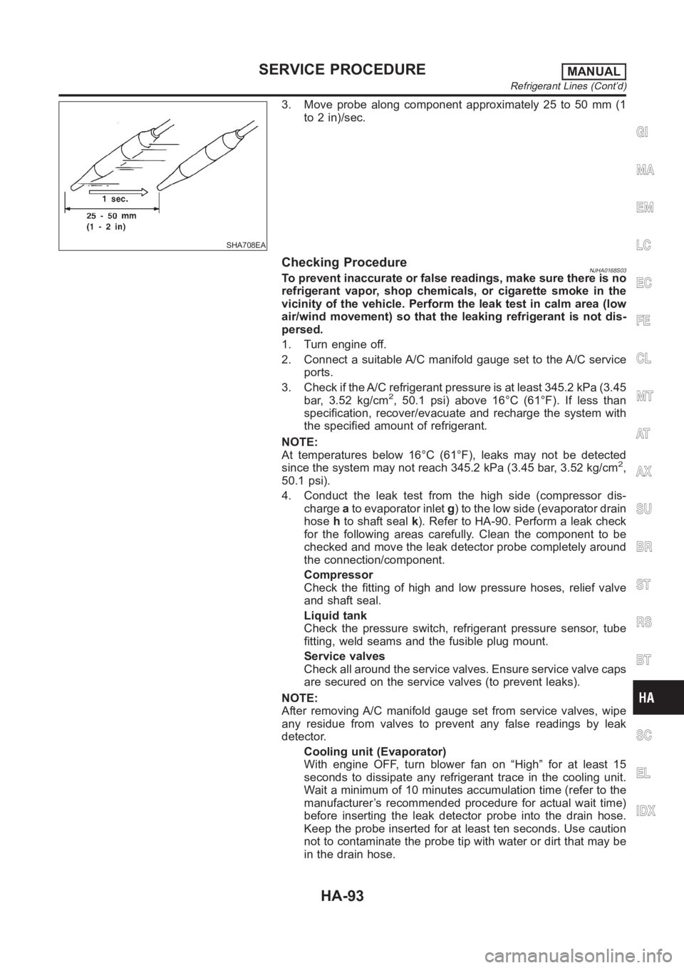
SHA708EA
3. Move probe along component approximately 25 to 50 mm (1
to 2 in)/sec.
Checking ProcedureNJHA0168S03To prevent inaccurate or false readings, make sure there is no
refrigerant vapor, shop chemicals, or cigarette smoke in the
vicinity of the vehicle. Perform the leak test in calm area (low
air/wind movement) so that the leaking refrigerant is not dis-
persed.
1. Turn engine off.
2. Connect a suitable A/C manifold gauge set to the A/C service
ports.
3. Check if the A/C refrigerant pressure is at least 345.2 kPa (3.45
bar, 3.52 kg/cm
2, 50.1 psi) above 16°C (61°F). If less than
specification, recover/evacuate and recharge the system with
the specified amount of refrigerant.
NOTE:
At temperatures below 16°C (61°F), leaks may not be detected
since the system may not reach 345.2 kPa (3.45 bar, 3.52 kg/cm
2,
50.1 psi).
4. Conduct the leak test from the high side (compressor dis-
chargeato evaporator inletg) to the low side (evaporator drain
hosehto shaft sealk). Refer to HA-90. Perform a leak check
for the following areas carefully. Clean the component to be
checked and move the leak detector probe completely around
the connection/component.
Compressor
Check the fitting of high and low pressure hoses, relief valve
and shaft seal.
Liquid tank
Check the pressure switch, refrigerant pressure sensor, tube
fitting, weld seams and the fusible plug mount.
Service valves
Check all around the service valves. Ensure service valve caps
are secured on the service valves (to prevent leaks).
NOTE:
After removing A/C manifold gauge set from service valves, wipe
any residue from valves to prevent any false readings by leak
detector.
Cooling unit (Evaporator)
With engine OFF, turn blower fan on “High” for at least 15
seconds to dissipate any refrigerant trace in the cooling unit.
Wait a minimum of 10 minutes accumulation time (refer to the
manufacturer’s recommended procedure for actual wait time)
before inserting the leak detector probe into the drain hose.
Keep the probe inserted for at least ten seconds. Use caution
not to contaminate the probe tip with water or dirt that may be
in the drain hose.
GI
MA
EM
LC
EC
FE
CL
MT
AT
AX
SU
BR
ST
RS
BT
SC
EL
IDX
SERVICE PROCEDUREMANUAL
Refrigerant Lines (Cont’d)
HA-93