Page 2071 of 3189

TROUBLE DIAGNOSIS
ATC-91
C
D
E
F
G
H
I
K
L
MA
B
AT C
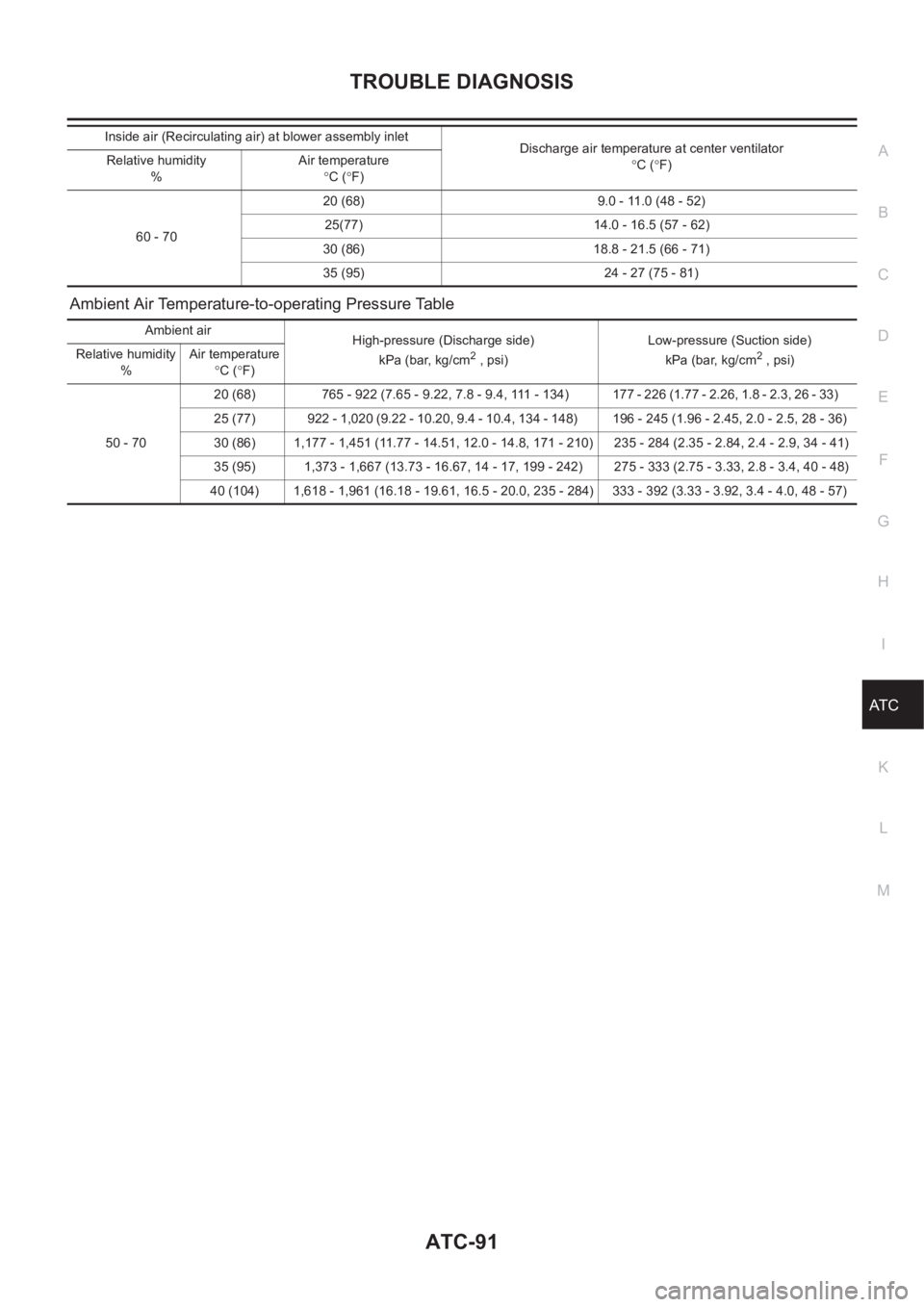
Ambient Air Temperature-to-operating Pressure Table
60 - 7020 (68) 9.0 - 11.0 (48 - 52)
25(77) 14.0 - 16.5 (57 - 62)
30 (86) 18.8 - 21.5 (66 - 71)
35 (95) 24 - 27 (75 - 81) Inside air (Recirculating air) at blower assembly inlet
Discharge air temperature at center ventilator
°C (°F) Relative humidity
%Air temperature
°C (°F)
Ambient air
High-pressure (Discharge side)
kPa (bar, kg/cm
2 , psi)Low-pressure (Suction side)
kPa (bar, kg/cm2 , psi) Relative humidity
%Air temperature
°C (°F)
50 - 7020 (68) 765 - 922 (7.65 - 9.22, 7.8 - 9.4, 111 - 134) 177 - 226 (1.77 - 2.26, 1.8 - 2.3, 26 - 33)
25 (77) 922 - 1,020 (9.22 - 10.20, 9.4 - 10.4, 134 - 148) 196 - 245 (1.96 - 2.45, 2.0 - 2.5, 28 - 36)
30 (86) 1,177 - 1,451 (11.77 - 14.51, 12.0 - 14.8, 171 - 210) 235 - 284 (2.35 - 2.84, 2.4 - 2.9, 34 - 41)
35 (95) 1,373 - 1,667 (13.73 - 16.67, 14 - 17, 199 - 242) 275 - 333 (2.75 - 3.33, 2.8 - 3.4, 40 - 48)
40 (104) 1,618 - 1,961 (16.18 - 19.61, 16.5 - 20.0, 235 - 284) 333 - 392 (3.33 - 3.92, 3.4 - 4.0, 48 - 57)
Page 2076 of 3189
ATC-96
TROUBLE DIAGNOSIS
*7AT C - 5 7 , "LAN System Circuit"*8ATC-69, "Blower Motor Circuit"*9AT C - 6 3 , "Air Mix Door Motor Circuit"
*10 QG engine (With EURO–OBD): EC-
144, "DTC P0117, P0118 ECT SEN-
SOR"
QG engine (Without EURO–OBD):
EC-501, "
DTC P0117, P0118 ECT
SENSOR"
YD engine: EC-84, "P0115 COOL-
ANT TEMP SEN" *11 QG engine: LC-17, "Changing
Engine Coolant"
YD engine: LC-43, "Changing
Engine Coolant" *12 QG engine: LC-17, "Changing
Engine Coolant"
YD engine: LC-43, "Changing
Engine Coolant"
Page 2099 of 3189

BLOWER UNIT
ATC-119
C
D
E
F
G
H
I
K
L
MA
B
AT C
BLOWER UNITPFP:27200
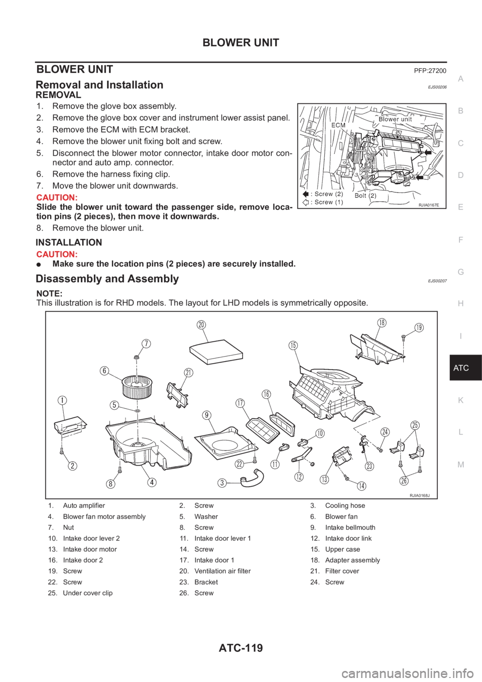
Removal and InstallationEJS00206
REMOVAL
1. Remove the glove box assembly.
2. Remove the glove box cover and instrument lower assist panel.
3. Remove the ECM with ECM bracket.
4. Remove the blower unit fixing bolt and screw.
5. Disconnect the blower motor connector, intake door motor con-
nector and auto amp. connector.
6. Remove the harness fixing clip.
7. Move the blower unit downwards.
CAUTION:
Slide the blower unit toward the passenger side, remove loca-
tion pins (2 pieces), then move it downwards.
8. Remove the blower unit.
INSTALLATION
CAUTION:
●Make sure the location pins (2 pieces) are securely installed.
Disassembly and AssemblyEJS00207
NOTE:
This illustration is for RHD models. The layout for LHD models is symmetrically opposite.
RJIA0167E
1. Auto amplifier 2. Screw 3. Cooling hose
4. Blower fan motor assembly 5. Washer 6. Blower fan
7. Nut 8. Screw 9. Intake bellmouth
10. Intake door lever 2 11. Intake door lever 1 12. Intake door link
13. Intake door motor 14. Screw 15. Upper case
16. Intake door 2 17. Intake door 1 18. Adapter assembly
19. Screw 20. Ventilation air filter 21. Filter cover
22. Screw 23. Bracket 24. Screw
25. Under cover clip 26. Screw
RJIA0168J
Page 2100 of 3189
ATC-120
BLOWER MOTOR
BLOWER MOTOR
PFP:27226
Removal and InstallationEJS00208
1. Remove the blower unit. Refer to AT C - 11 9 , "Removal and Instal-
lation" .
2. Remove the auto amp.
3. Remove the blower unit fixing screw, then separate the blower
unit.
4. Remove the cooling hose and blower fan.
RJIA0169E
RJIA0356E
Page 2101 of 3189
INTAKE DOOR MOTOR
ATC-121
C
D
E
F
G
H
I
K
L
MA
B
AT C
INTAKE DOOR MOTORPFP:27730
Removal and InstallationEJS00209
1. Remove the blower unit. Refer to AT C - 11 9 , "Removal and Instal-
lation"
2. Remove the intake door motor from the blower unit.
RJIA0822E
RJIA1721E
Page 2102 of 3189
ATC-122
HEATER & COOLING UNIT ASSEMBLY
HEATER & COOLING UNIT ASSEMBLY
PFP:27110
Removal and InstallationEJS0020A
REMOVAL
1. Use the refrigerant collecting equipment (For HFC-134a) to dis-
charge the refrigerant from A/C system.
2. Drain coolant from cooling system. Refer to LC-17, "Changing
Engine Coolant" for QG engine, LC-43, "Changing Engine Cool-
ant" for YD engine.
3. Disconnect two heater hoses from heater core pipe.
4. Disconnect the low-pressure flexible hose and high-pressure
pipe from the evaporator.
CAUTION:
Cap or wrap the joint of the low-pressure flexible hose and the
high-pressure pipe with a suitable tool such as a vinyl tape to
avoid the entry of air.
5. Remove the instrument panel assembly.
6. Remove the blower unit.
7. Remove clips of vehicle harness from steering member.
8. Remove the instrument stay.
RJIA1734E
RJIA1722E
RJIA1723E
Page 2108 of 3189
ATC-128
VENTILATION AIR FILTER
VENTILATION AIR FILTER
PFP:27277
Removal and InstallationEJS0020F
FUNCTION
Air inside passenger compartment is kept clean at either recircula-
tion or fresh mode by installing ventilation air filter into blower unit.
REPLACEMENT TIMING
Refer to MA-5 (Except for Europe), MA-8 or MA-10 (For Europe), “CHASSIS AND BODY MAINTENANCE”.
Caution label is fixed inside the glove box.
REPLACEMENT AND PROCEDURES
1. Remove the glove box.
2. Remove the ventilation air filter cover.
3. Take out the ventilation air filter from blower unit.
4. Replace with new one and reinstall on blower unit.
5. Reinstall the glove box.
RHA680H
RHA681H
Page 2127 of 3189

REFRIGERANT LINES
ATC-147
C
D
E
F
G
H
I
K
L
MA
B
AT C
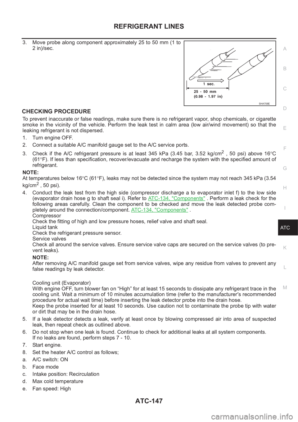
3. Move probe along component approximately 25 to 50 mm (1 to
2 in)/sec.
CHECKING PROCEDURE
To prevent inaccurate or false readings, make sure there is no refrigerant vapor, shop chemicals, or cigarette
smoke in the vicinity of the vehicle. Perform the leak test in calm area (low air/wind movement) so that the
leaking refrigerant is not dispersed.
1. Turn engine OFF.
2. Connect a suitable A/C manifold gauge set to the A/C service ports.
3. Check if the A/C refrigerant pressure is at least 345 kPa (3.45 bar, 3.52 kg/cm
2 , 50 psi) above 16°C
(61°F). If less than specification, recover/evacuate and recharge the system with the specified amount of
refrigerant.
NOTE:
At temperatures below 16°C (61°F), leaks may not be detected since the system may not reach 345 kPa (3.54
kg/cm
2 , 50 psi).
4. Conduct the leak test from the high side (compressor discharge a to evaporator inlet f) to the low side
(evaporator drain hose g to shaft seal i). Refer to AT C - 1 3 4 , "
Components" . Perform a leak check for the
following areas carefully. Clean the component to be checked and move the leak detected probe com-
pletely around the connection/component. ATC-134, "
Components" .
Compressor
Check the fitting of high and low pressure hoses, relief valve and shaft seal.
Liquid tank
Check the refrigerant pressure sensor.
Service valves
Check all around the service valves. Ensure service valve caps are secured on the service valves (to pre-
vent leaks).
NOTE:
After removing A/C manifold gauge set from service valves, wipe any residue from valves to prevent any
false readings by leak detector.
Cooling unit (Evaporator)
With engine OFF, turn blower fan on “High” for at least 15 seconds to dissipate any refrigerant trace in the
cooling unit. Wait a minimum of 10 minutes accumulation time (refer to the manufacturer′s recommended
procedure for actual wait time) before inserting the leak detector probe into the drain hose.
Keep the probe inserted for at least 10 seconds. Use caution not to contaminate the probe tip with water
or dirt that may be in the drain hose.
5. If a leak detector detects a leak, verify at least once by blowing compressed air into area of suspected
leak, then repeat check as outlined above.
6. Do not stop when one leak is found. Continue to check for additional leaks at all system components.
If no leaks are found, perform steps 7 - 10.
7. Start engine.
8. Set the heater A/C control as follows;
a. A/C switch: ON
b. Face mode
c. Intake position: Recirculation
d. Max cold temperature
e. Fan speed: High
SHA708E