2003 NISSAN ALMERA N16 blower
[x] Cancel search: blowerPage 1190 of 3189
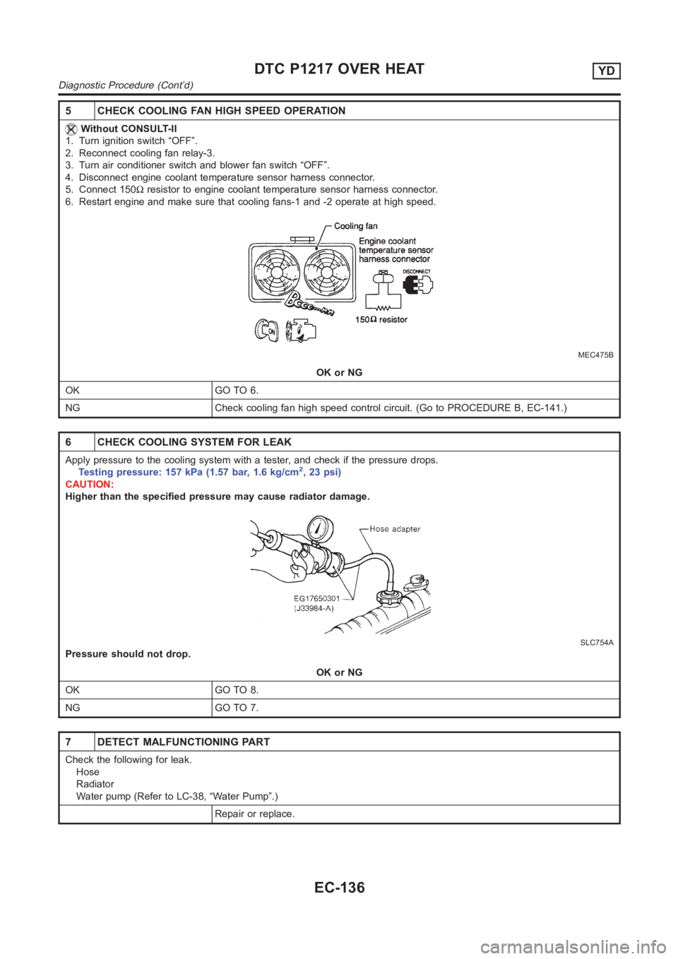
5 CHECK COOLING FAN HIGH SPEED OPERATION
Without CONSULT-II
1. Turn ignition switch “OFF”.
2. Reconnect cooling fan relay-3.
3. Turn air conditioner switch and blower fan switch “OFF”.
4. Disconnect engine coolant temperature sensor harness connector.
5. Connect 150Ωresistor to engine coolant temperature sensor harness connector.
6. Restart engine and make sure that cooling fans-1 and -2 operate at high speed.
MEC475B
OK or NG
OK GO TO 6.
NG Check cooling fan high speed control circuit. (Go to PROCEDURE B, EC-141.)
6 CHECK COOLING SYSTEM FOR LEAK
Apply pressure to the cooling system with a tester, and check if the pressure drops.
Testing pressure: 157 kPa (1.57 bar, 1.6 kg/cm2,23psi)
CAUTION:
Higher than the specified pressure may cause radiator damage.
SLC754A
Pressure should not drop.
OK or NG
OK GO TO 8.
NG GO TO 7.
7 DETECT MALFUNCTIONING PART
Check the following for leak.
Hose
Radiator
Water pump (Refer to LC-38, “Water Pump”.)
Repair or replace.
DTC P1217 OVER HEATYD
Diagnostic Procedure (Cont’d)
EC-136
Page 1982 of 3189
ATC-2
Discharge Air Flow ................................................. 27
System Description ................................................. 28
SWITCHES AND THEIR CONTROL FUNCTION ... 28
TROUBLE DIAGNOSIS ............................................ 29
How to Perform Trouble Diagnoses for Quick and
Accurate Repair ...................................................... 29
WORK FLOW ...................................................... 29
SYMPTOM TABLE .............................................. 29
Component Parts and Harness Connector Location ... 30
ENGINE COMPARTMENT .................................. 30
PASSENGER COMPARTMENT .......................... 31
Circuit Diagram ....................................................... 32
Wiring Diagram ....................................................... 33
Auto Amp. Terminals and Reference Value ............ 40
PIN CONNECTOR TERMINAL LAYOUT ............ 40
AUTO AMP. INSPECTION TABLE ...................... 40
Self-diagnosis Function .......................................... 42
DESCRIPTION .................................................... 42
FUNCTION CONFIRMATION PROCEDURE ...... 43
AUXILIARY MECHANISM: TEMPERATURE
SETTING TRIMMER ........................................... 49
Operational Check .................................................. 51
CHECKING MEMORY FUNCTION ..................... 51
CHECKING BLOWER ......................................... 51
CHECKING DISCHARGE AIR ............................ 52
CHECKING RECIRCULATION ............................ 53
CHECKING FRESH SWITCH ............................. 53
CHECKING TEMPERATURE DECREASE ......... 53
CHECKING TEMPERATURE INCREASE .......... 53
CHECKING AUTO MODE ................................... 54
Power Supply and Ground Circuit for Auto Amp. ... 55
INSPECTION FLOW ........................................... 55
COMPONENT DESCRIPTION ............................ 55
DIAGNOSTIC PROCEDURE FOR A/C SYSTEM ... 56
LAN System Circuit ............................................. ... 57
DIAGNOSTIC PROCEDURE FOR LAN SYS-
TEM CIRCUIT ..................................................... 57
Mode Door Motor Circuit ........................................ 59
INSPECTION FLOW ........................................... 60
SYSTEM DESCRIPTION .................................... 61
COMPONENT DESCRIPTION ............................ 62
DIAGNOSTIC PROCEDURE FOR MODE
DOOR .................................................................. 62
Air Mix Door Motor Circuit ...................................... 63
INSPECTION FLOW ........................................... 63
SYSTEM DESCRIPTION .................................... 64
COMPONENT DESCRIPTION ............................ 65
DIAGNOSTIC PROCEDURE FOR AIR MIX
DOOR MOTOR ................................................... 65
Intake Door Motor Circuit ........................................ 66
INSPECTION FLOW ........................................... 66
SYSTEM DESCRIPTION .................................
... 67
COMPONENT DESCRIPTION ............................ 67
DIAGNOSTIC PROCEDURE FOR INTAKE
DOOR MOTOR ................................................... 68
Blower Motor Circuit ............................................... 69
INSPECTION FLOW ........................................... 69
SYSTEM DESCRIPTION .................................... 70
COMPONENT DESCRIPTION ............................ 71DIAGNOSTIC PROCEDURE FOR BLOWER
MOTOR ................................................................ 71
COMPONENT INSPECTION ............................... 74
Magnet Clutch Circuit .............................................. 75
INSPECTION FLOW ............................................ 75
SYSTEM DESCRIPTION ..................................... 76
DIAGNOSTIC PROCEDURE FOR MAGNET
CLUTCH (WITH CAN SYSTEM) ......................... 76
DIAGNOSTIC PROCEDURE FOR MAGNET
CLUTCH (YD ENGINE WITHOUT COMMON
RAIL) .................................................................... 81
COMPONENT INSPECTION ............................... 85
Insufficient Cooling .................................................. 86
INSPECTION FLOW ............................................ 86
PERFORMANCE TEST DIAGNOSES ................ 88
PERFORMANCE CHART .................................... 90
TROUBLE DIAGNOSES FOR UNUSUAL PRES-
SURE ................................................................... 92
Insufficient Heating ................................................. 95
INSPECTION FLOW ............................................ 95
Noise ....................................................................... 97
INSPECTION FLOW ............................................ 97
Self-diagnosis ......................................................... 98
INSPECTION FLOW ............................................ 98
Memory Function .................................................... 99
INSPECTION FLOW ............................................ 99
Ambient Sensor Circuit .........................................100
COMPONENT DESCRIPTION ..........................100
AMBIENT TEMPERATURE INPUT PROCESS .100
DIAGNOSTIC PROCEDURE FOR AMBIENT
SENSOR ............................................................100
COMPONENT INSPECTION .............................102
In-vehicle Sensor Circuit .......................................102
COMPONENT DESCRIPTION ..........................102
DIAGNOSTIC PROCEDURE FOR IN-VEHICLE
SENSOR ............................................................103
COMPONENT INSPECTION .............................104
Sunload Sensor Circuit .........................................105
COMPONENT DESCRIPTION ..........................105
SUNLOAD INPUT PROCESS ...........................105
DIAGNOSTIC PROCEDURE FOR SUNLOAD
SENSOR ............................................................105
COMPONENT INSPECTION .............................107
Intake Sensor Circuit .............................................108
COMPONENT DESCRIPTION ..........................108
DIAGNOSTIC PROCEDURE FOR INTAKE SEN-
SOR ...................................................................108
Multiplex Communication Circuit ...........................109
DIAGNOSTIC PROCEDURE FOR MULTIPLEX
COMMUNICATION CIRCUIT ............................109
CONTROLLER ........................................................113
Removal and Installation .......................................113
AUTO AMP ..............................................................114
REMOVAL AND INSTALLATION ..........................114
AMBIENT SENSOR ................................................115
Removal and Installation .......................................115
IN-VEHICLE SENSOR ............................................116
Removal and Installation .......................................116
Page 1983 of 3189
ATC-3
C
D
E
F
G
H
I
K
L
MA
B
AT C SUNLOAD SENSOR ...............................................117
Removal and Installation ....................................... 117
INTAKE SENSOR CIRCUIT ....................................118
Removal and Installation ....................................... 118
BLOWER UNIT ........................................................119
Removal and Installation ....................................... 119
REMOVAL .......................................................... 119
INSTALLATION .................................................. 119
Disassembly and Assembly .................................. 119
BLOWER MOTOR .................................................. 120
Removal and Installation ...................................... 120
INTAKE DOOR MOTOR ......................................... 121
Removal and Installation ...................................... 121
HEATER & COOLING UNIT ASSEMBLY .............. 122
Removal and Installation ...................................... 122
REMOVAL ......................................................... 122
INSTALLATION ................................................. 123
Disassembly and Assembly ................................. 123
MODE DOOR MOTOR ........................................... 125
Removal and Installation ...................................... 125
AIR MIX DOOR MOTOR ......................................... 126
Removal and Installation ...................................... 126
FAN CONTROL AMPLIFIER .................................. 127
Removal and Installation ...................................... 127
VENTILATION AIR FILTER .................................... 128
Removal and Installation ...................................... 128
FUNCTION ........................................................ 128
REPLACEMENT TIMING .................................. 128
REPLACEMENT AND PROCEDURES ............ 128
HEATER CORE ...................................................... 129
Removal and Installation ...................................... 129
DUCTS AND GRILLES .......................................... 130
Removal and Installation ...................................... 130
VENTILATOR DUCT, DEFROSTER NOZZLE
AND DEFROSTER DUCTS .............................. 130
CENTER VENTILATOR GRILLE ...................... 130
SIDE VENTILATOR GRILLE ............................. 130
FOOT DUCT ..................................................... 130
FLOOR DUCT ................................................... 131
REFRIGERANT LINES ........................................... 132
HFC-134a (R-134a) Service Procedure ............... 132
SETTING OF SERVICE TOOLS AND EQUIP-
MENT ................................................................ 132Components .........................................................134
Compressor ..........................................................136
REMOVAL .........................................................136
INSTALLATION .................................................137
Compressor Clutch .............................................. .138
REMOVAL .........................................................138
INSTALLATION .................................................139
Low-pressure Flexible Hose .................................141
REMOVAL .........................................................141
INSTALLATION .................................................141
High-pressure Flexible Hose ................................141
REMOVAL .........................................................141
INSTALLATION .................................................142
High-pressure Pipe ...............................................142
REMOVAL .........................................................142
INSTALLATION .................................................142
Refrigerant Pressure Sensor ................................142
REMOVAL AND INSTALLATION ......................142
Dual-pressure Switch ...........................................143
REMOVAL AND INSTALLATION ......................143
Condenser Assembly ...........................................143
REMOVAL .........................................................143
INSTALLATION .................................................143
Evaporator ............................................................144
REMOVAL .........................................................144
INSTALLATION .................................................144
Expansion Valve ...................................................144
REMOVAL .........................................................144
INSTALLATION .................................................144
Checking for Refrigerant Leaks ............................145
Checking System for Leaks Using the Fluorescent
Leak Detector .......................................................145
Dye Injection .........................................................146
Electronic Refrigerant Leak Detector ....................146
PRECAUTIONS FOR HANDLING LEAK
DETECTOR .......................................................146
CHECKING PROCEDURE ...............................147
SERVICE DATA AND SPECIFICATIONS (SDS) ....149
Compressor ..........................................................149
Lubricant ...............................................................149
Refrigerant ............................................................149
Engine Idling Speed .............................................149
Belt Tension ..........................................................149
Page 2000 of 3189
ATC-20
LUBRICANT
LUBRICANT
PFP:KLG00
Maintenance of Lubricant Quantity in CompressorEJS001Z4
The lubricant in the compressor circulates through the system with the refrigerant. Add lubricant to compres-
sor when replacing any component or after a large gas leakage occurred. It is important to maintain the speci-
fied amount.
If lubricant quantity is not maintained properly, the following malfunctions may result:
●Lack of lubricant: May lead to a seized compressor
●Excessive lubricant: Inadequate cooling (thermal exchange interference)
LUBRICANT
LUBRICANT RETURN OPERATION
Adjust the lubricant quantity according to the test group shown below.
1. CHECK LUBRICANT RETURN OPERATION
Can lubricant return operation be performed?
●A/C system works properly.
●There is no evidence of a large amount of lubricant leakage.
Ye s o r N o
Yes >> GO TO 2.
No >> GO TO 3.
2. PERFORM LUBRICANT RETURN OPERATION, PROCEEDING AS FOLLOWS:
1. Start engine, and set the following conditions:
–Test condition
Engine speed: Idling to 1,200 rpm
A/C or AUTO switch: ON
Blower speed: Max. position
Temp. control: Optional [Set so that intake air temperature is 25 to 30°C (77 to 86°F).]
Intake position: Recirculation (REC)
2. Perform lubricant return operation for about 10 minutes.
3. Stop engine.
CAUTION:
If excessive lubricant leakage is noted, do not perform the lubricant return operation.
>> GO TO 3.
3. CHECK COMPRESSOR
Should the compressor be replaced?
Ye s o r N o
Ye s > > G o t o AT C - 2 1 , "LUBRICANT ADJUSTING PROCEDURE FOR COMPRESSOR REPLACE-
MENT" .
No >> GO TO 4.Name Nissan A/C System Oil Type S
Part number KLH00-PAGS0
Page 2004 of 3189
ATC-24
AIR CONDITIONER CONTROL
FAN SPEED CONTROL
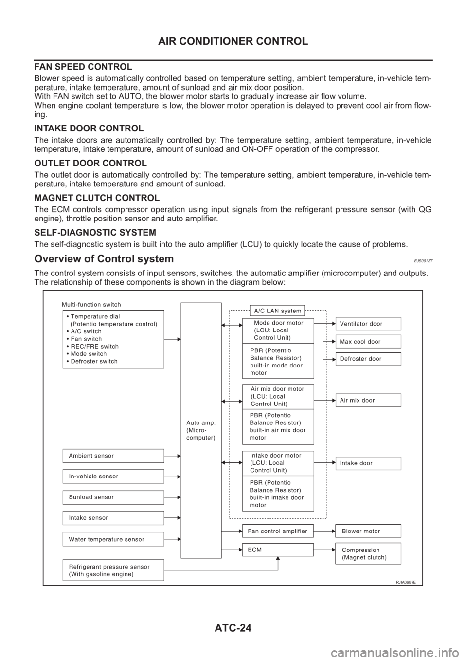
Blower speed is automatically controlled based on temperature setting, ambient temperature, in-vehicle tem-
perature, intake temperature, amount of sunload and air mix door position.
With FAN switch set to AUTO, the blower motor starts to gradually increase air flow volume.
When engine coolant temperature is low, the blower motor operation is delayed to prevent cool air from flow-
ing.
INTAKE DOOR CONTROL
The intake doors are automatically controlled by: The temperature setting, ambient temperature, in-vehicle
temperature, intake temperature, amount of sunload and ON-OFF operation of the compressor.
OUTLET DOOR CONTROL
The outlet door is automatically controlled by: The temperature setting, ambient temperature, in-vehicle tem-
perature, intake temperature and amount of sunload.
MAGNET CLUTCH CONTROL
The ECM controls compressor operation using input signals from the refrigerant pressure sensor (with QG
engine), throttle position sensor and auto amplifier.
SELF-DIAGNOSTIC SYSTEM
The self-diagnostic system is built into the auto amplifier (LCU) to quickly locate the cause of problems.
Overview of Control systemEJS001Z7
The control system consists of input sensors, switches, the automatic amplifier (microcomputer) and outputs.
The relationship of these components is shown in the diagram below:
RJIA0687E
Page 2005 of 3189
AIR CONDITIONER CONTROL
ATC-25
C
D
E
F
G
H
I
K
L
MA
B
AT C
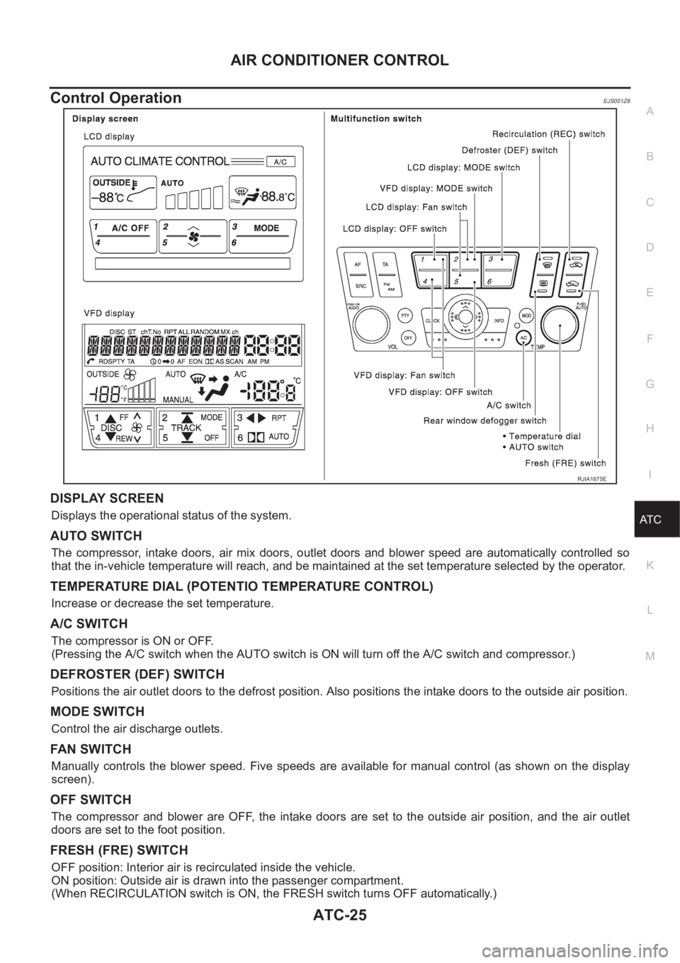
Control OperationEJS001Z8
DISPLAY SCREEN
Displays the operational status of the system.
AUTO SWITCH
The compressor, intake doors, air mix doors, outlet doors and blower speed are automatically controlled so
that the in-vehicle temperature will reach, and be maintained at the set temperature selected by the operator.
TEMPERATURE DIAL (POTENTIO TEMPERATURE CONTROL)
Increase or decrease the set temperature.
A/C SWITCH
The compressor is ON or OFF.
(Pressing the A/C switch when the AUTO switch is ON will turn off the A/C switch and compressor.)
DEFROSTER (DEF) SWITCH
Positions the air outlet doors to the defrost position. Also positions the intake doors to the outside air position.
MODE SWITCH
Control the air discharge outlets.
FAN SWITCH
Manually controls the blower speed. Five speeds are available for manual control (as shown on the display
screen).
OFF SWITCH
The compressor and blower are OFF, the intake doors are set to the outside air position, and the air outlet
doors are set to the foot position.
FRESH (FRE) SWITCH
OFF position: Interior air is recirculated inside the vehicle.
ON position: Outside air is drawn into the passenger compartment.
(When RECIRCULATION switch is ON, the FRESH switch turns OFF automatically.)
RJIA1675E
Page 2006 of 3189
ATC-26
AIR CONDITIONER CONTROL
RECIRCULATION (REC) SWITCH
OFF position: Outside air is drawn into the passenger compartment.
ON position: Interior air is drawn into the passenger compartment.
(When the FRESH switch is ON or the compressor is turned from ON to OFF, the RECIRCULATION switch
turns OFF automatically.)
REAR WINDOW DEFOGGER SWITCH
When illumination is ON, rear window is defogged.
Fail-safe FunctionEJS001Z9
If fail-safe request signal is sent from AV control unit, or if communication error exists between auto amplifier
and AV control unit for at least 30 seconds, air conditioner is controlled under following conditions.
Compressor : ON
Air inlet : Fresh
Air outlet : AUTO
Blower fan speed : AUTO
Set temperature : Setting before communication error occurs
Page 2009 of 3189
TROUBLE DIAGNOSIS
ATC-29
C
D
E
F
G
H
I
K
L
MA
B
AT C
TROUBLE DIAGNOSISPFP:00004
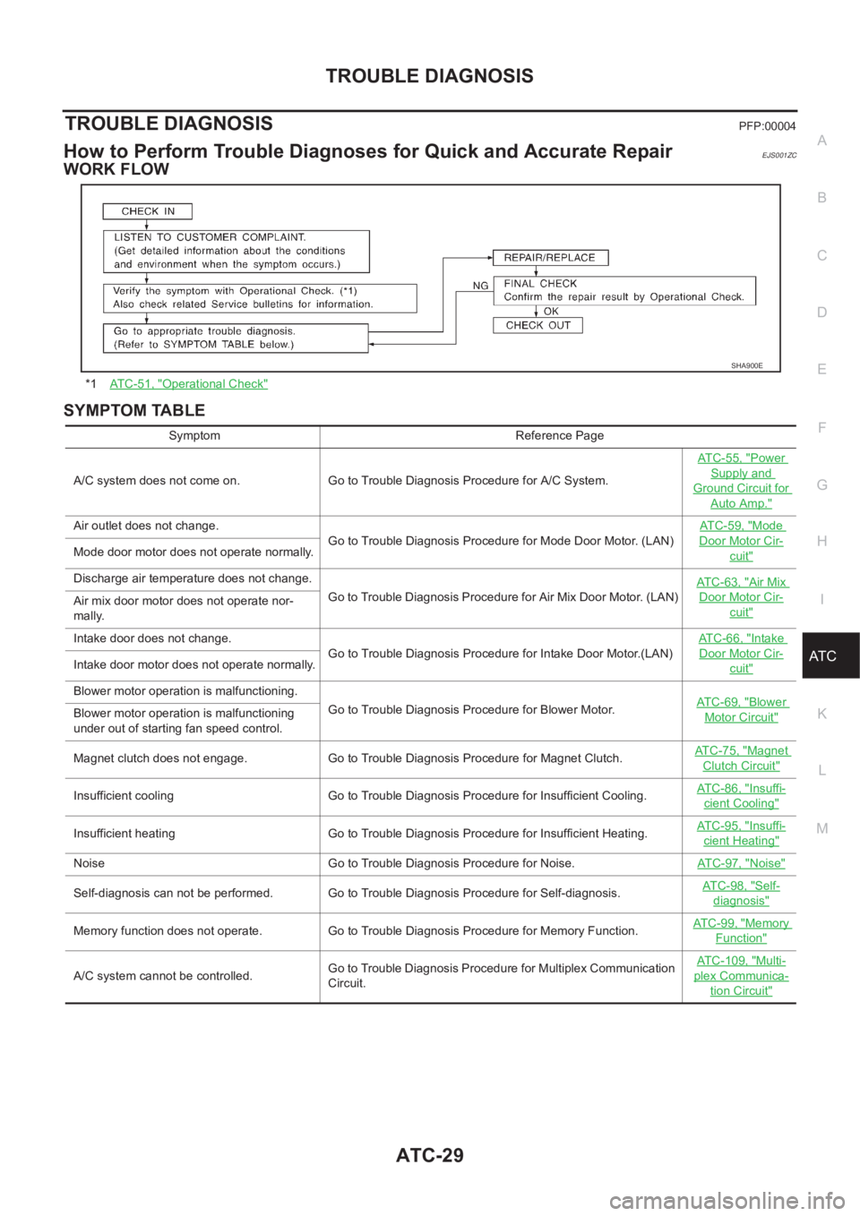
How to Perform Trouble Diagnoses for Quick and Accurate RepairEJS001ZC
WORK FLOW
SYMPTOM TABLE
*1AT C - 5 1 , "Operational Check"
SHA900E
Symptom Reference Page
A/C system does not come on. Go to Trouble Diagnosis Procedure for A/C System.ATC-55, "
Power
Supply and
Ground Circuit for
Auto Amp."
Air outlet does not change.
Go to Trouble Diagnosis Procedure for Mode Door Motor. (LAN)AT C - 5 9 , "Mode
Door Motor Cir-
cuit"Mode door motor does not operate normally.
Discharge air temperature does not change.
Go to Trouble Diagnosis Procedure for Air Mix Door Motor. (LAN)ATC-63, "
Air Mix
Door Motor Cir-
cuit"Air mix door motor does not operate nor-
mally.
Intake door does not change.
Go to Trouble Diagnosis Procedure for Intake Door Motor.(LAN)AT C - 6 6 , "
Intake
Door Motor Cir-
cuit"Intake door motor does not operate normally.
Blower motor operation is malfunctioning.
Go to Trouble Diagnosis Procedure for Blower Motor.ATC-69, "
Blower
Motor Circuit"Blower motor operation is malfunctioning
under out of starting fan speed control.
Magnet clutch does not engage. Go to Trouble Diagnosis Procedure for Magnet Clutch.AT C - 7 5 , "
Magnet
Clutch Circuit"
Insufficient cooling Go to Trouble Diagnosis Procedure for Insufficient Cooling.AT C - 8 6 , "Insuffi-
cient Cooling"
Insufficient heating Go to Trouble Diagnosis Procedure for Insufficient Heating.AT C - 9 5 , "Insuffi-
cient Heating"
Noise Go to Trouble Diagnosis Procedure for Noise.ATC-97, "Noise"
Self-diagnosis can not be performed. Go to Trouble Diagnosis Procedure for Self-diagnosis.AT C - 9 8 , "Self-
diagnosis"
Memory function does not operate. Go to Trouble Diagnosis Procedure for Memory Function.AT C - 9 9 , "Memory
Function"
A/C system cannot be controlled.Go to Trouble Diagnosis Procedure for Multiplex Communication
Circuit.ATC-109, "
Multi-
plex Communica-
tion Circuit"