2003 NISSAN ALMERA N16 ec-78
[x] Cancel search: ec-78Page 408 of 3189
![NISSAN ALMERA N16 2003 Electronic Repair Manual EC-78
[QG (WITH EURO-OBD)]
TROUBLE DIAGNOSIS
Circuit Diagram
EBS00K3R
YEC274A NISSAN ALMERA N16 2003 Electronic Repair Manual EC-78
[QG (WITH EURO-OBD)]
TROUBLE DIAGNOSIS
Circuit Diagram
EBS00K3R
YEC274A](/manual-img/5/57350/w960_57350-407.png)
EC-78
[QG (WITH EURO-OBD)]
TROUBLE DIAGNOSIS
Circuit Diagram
EBS00K3R
YEC274A
Page 1058 of 3189
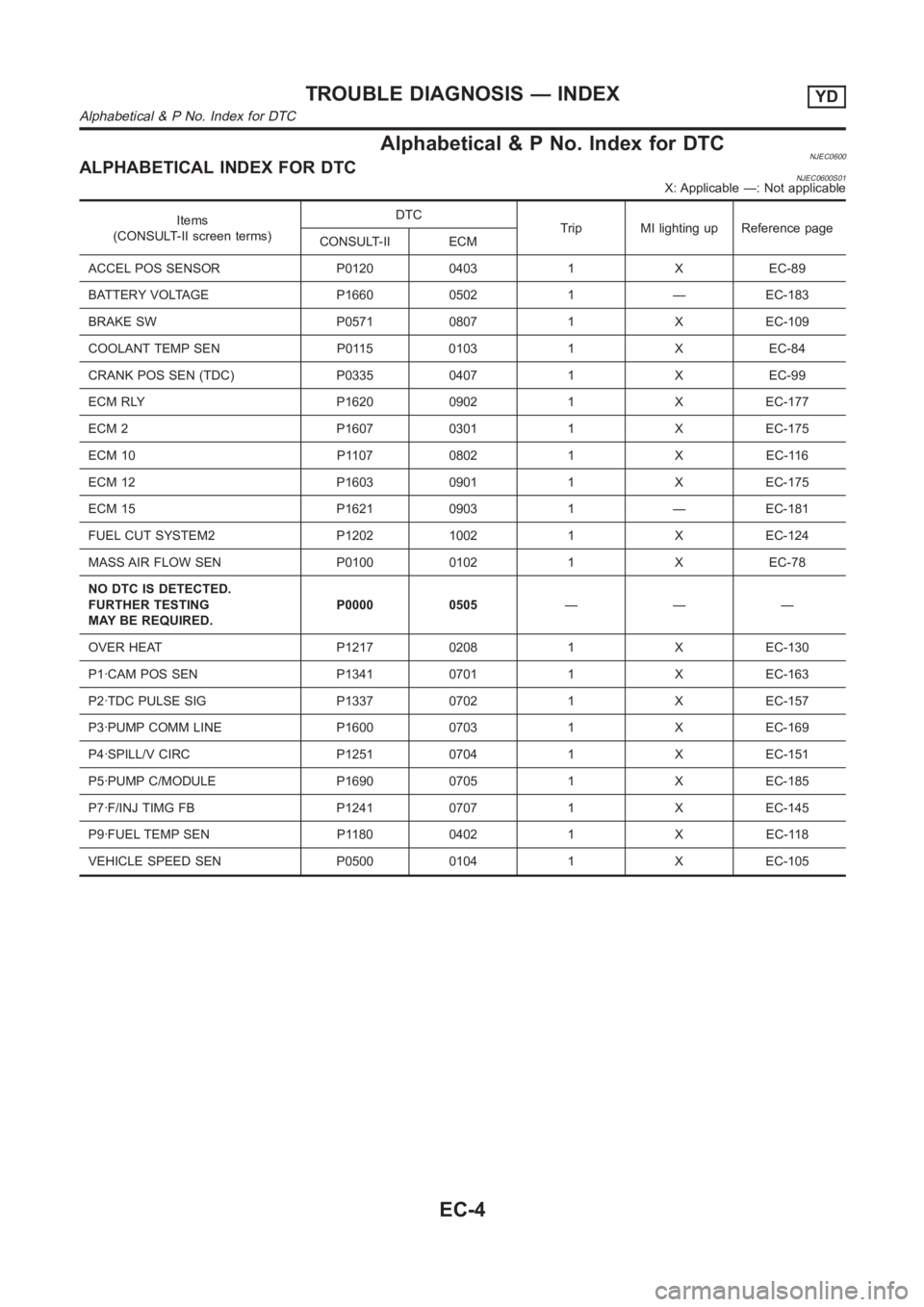
Alphabetical & P No. Index for DTCNJEC0600ALPHABETICAL INDEX FOR DTCNJEC0600S01X: Applicable —: Not applicable
Items
(CONSULT-II screen terms)DTC
Trip MI lighting up Reference page
CONSULT-II ECM
ACCEL POS SENSOR P0120 0403 1 X EC-89
BATTERY VOLTAGE P1660 0502 1 — EC-183
BRAKE SW P0571 0807 1 X EC-109
COOLANT TEMP SEN P0115 0103 1 X EC-84
CRANK POS SEN (TDC) P0335 0407 1 X EC-99
ECM RLY P1620 0902 1 X EC-177
ECM 2 P1607 0301 1 X EC-175
ECM 10 P1107 0802 1 X EC-116
ECM 12 P1603 0901 1 X EC-175
ECM 15 P1621 0903 1 — EC-181
FUEL CUT SYSTEM2 P1202 1002 1 X EC-124
MASS AIR FLOW SEN P0100 0102 1 X EC-78
NO DTC IS DETECTED.
FURTHER TESTING
MAY BE REQUIRED.P0000 0505———
OVER HEAT P1217 0208 1 X EC-130
P1·CAM POS SEN P1341 0701 1 X EC-163
P2·TDC PULSE SIG P1337 0702 1 X EC-157
P3·PUMP COMM LINE P1600 0703 1 X EC-169
P4·SPILL/V CIRC P1251 0704 1 X EC-151
P5·PUMP C/MODULE P1690 0705 1 X EC-185
P7·F/INJ TIMG FB P1241 0707 1 X EC-145
P9·FUEL TEMP SEN P1180 0402 1 X EC-118
VEHICLE SPEED SEN P0500 0104 1 X EC-105
TROUBLE DIAGNOSIS — INDEXYD
Alphabetical & P No. Index for DTC
EC-4
Page 1059 of 3189
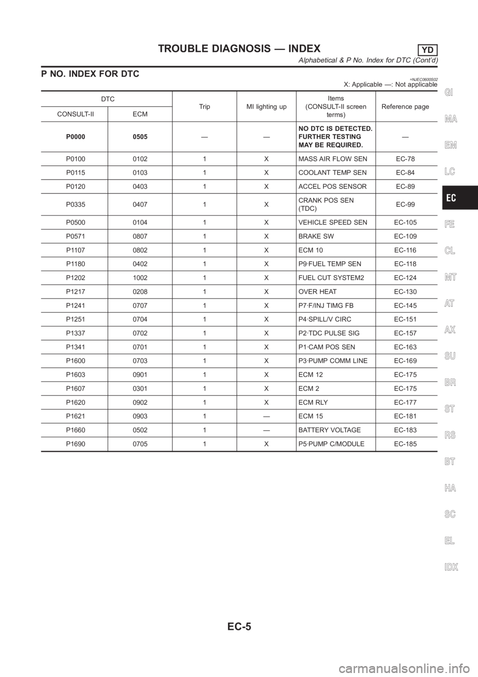
P NO. INDEX FOR DTC=NJEC0600S02X: Applicable —: Not applicable
DTC
Trip MI lighting upItems
(CONSULT-II screen
terms)Reference page
CONSULT-II ECM
P0000 0505——NO DTC IS DETECTED.
FURTHER TESTING
MAY BE REQUIRED.—
P0100 0102 1 X MASS AIR FLOW SEN EC-78
P0115 0103 1 X COOLANT TEMP SEN EC-84
P0120 0403 1 X ACCEL POS SENSOR EC-89
P0335 0407 1 XCRANK POS SEN
(TDC)EC-99
P0500 0104 1 X VEHICLE SPEED SEN EC-105
P0571 0807 1 X BRAKE SW EC-109
P1107 0802 1 X ECM 10 EC-116
P1180 0402 1 X P9·FUEL TEMP SEN EC-118
P1202 1002 1 X FUEL CUT SYSTEM2 EC-124
P1217 0208 1 X OVER HEAT EC-130
P1241 0707 1 X P7·F/INJ TIMG FB EC-145
P1251 0704 1 X P4·SPILL/V CIRC EC-151
P1337 0702 1 X P2·TDC PULSE SIG EC-157
P1341 0701 1 X P1·CAM POS SEN EC-163
P1600 0703 1 X P3·PUMP COMM LINE EC-169
P1603 0901 1 X ECM 12 EC-175
P1607 0301 1 X ECM 2 EC-175
P1620 0902 1 X ECM RLY EC-177
P1621 0903 1 — ECM 15 EC-181
P1660 0502 1 — BATTERY VOLTAGE EC-183
P1690 0705 1 X P5·PUMP C/MODULE EC-185GI
MA
EM
LC
FE
CL
MT
AT
AX
SU
BR
ST
RS
BT
HA
SC
EL
IDX
TROUBLE DIAGNOSIS — INDEXYD
Alphabetical & P No. Index for DTC (Cont’d)
EC-5
Page 1109 of 3189
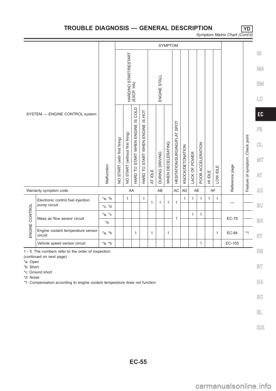
SYSTEM — ENGINE CONTROL system
Malfunction
SYMPTOM
Reference page
Feature of symptom, Check pointHARD/NO START/RESTART
(EXCP. HA)
ENGINE STALL
HESITATION/SURGING/FLAT SPOT
KNOCK/DETONATION
LACK OF POWER
POOR ACCELERATION
HI IDLE
LOW IDLE NO START (with first firing)
NO START (without first firing)
HARD TO START WHEN ENGINE IS COLD
HARD TO START WHEN ENGINE IS HOT
AT IDLE
DURING DRIVING
WHEN DECELERATINGWarranty symptom code AA AB AC AD AE AF
ENGINE CONTROL
Electronic control fuel injection
pump circuit*a, *b 1 1
111111111
—
*c, *d
Mass air flow sensor circuit*a, *c
111
EC-78
*b
Engine coolant temperature sensor
circuit*a, *b 1 1 1 1 EC-84 *1
Vehicle speed sensor circuit *a, *b 1 EC-105
1 - 5: The numbers refer to the order of inspection.
(continued on next page)
*a: Open
*b: Short
*c: Ground short
*d: Noise
*1: Compensation according to engine coolant temperature does not function.
GI
MA
EM
LC
FE
CL
MT
AT
AX
SU
BR
ST
RS
BT
HA
SC
EL
IDX
TROUBLE DIAGNOSIS — GENERAL DESCRIPTIONYD
Symptom Matrix Chart (Cont’d)
EC-55
Page 1110 of 3189
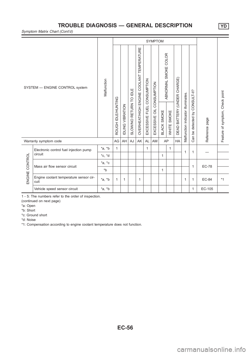
SYSTEM — ENGINE CONTROL system
Malfunction
SYMPTOM
Reference page
Feature of symptom, Check pointROUGH IDLE/HUNTING
IDLING VIBRATION
SLOW/NO RETURN TO IDLE
OVERHEAT/HIGH ENGINE COOLANT TEMPERATURE
EXCESSIVE FUEL CONSUMPTION
EXCESSIVE OIL CONSUMPTION
ABNORMAL SMOKE COLOR
DEAD BATTERY (UNDER CHARGE)
Malfunction indicator illuminates.
Can be detected by CONSULT-II?BLACK SMOKE
WHITE SMOKEWarranty symptom code AG AH AJ AK AL AM AP HA
ENGINE CONTROL
Electronic control fuel injection pump
circuit*a, *b 1 1 1
11 —
*c, *d 1
Mass air flow sensor circuit*a, *c
1 EC-78
*b 1
Engine coolant temperature sensor cir-
cuit*a, *b 1 1 1 1 1 EC-84 *1
Vehicle speed sensor circuit *a, *b 1 EC-105
1 - 5: The numbers refer to the order of inspection.
(continued on next page)
*a: Open
*b: Short
*c: Ground short
*d: Noise
*1: Compensation according to engine coolant temperature does not function.
TROUBLE DIAGNOSIS — GENERAL DESCRIPTIONYD
Symptom Matrix Chart (Cont’d)
EC-56
Page 1132 of 3189
SEF987W
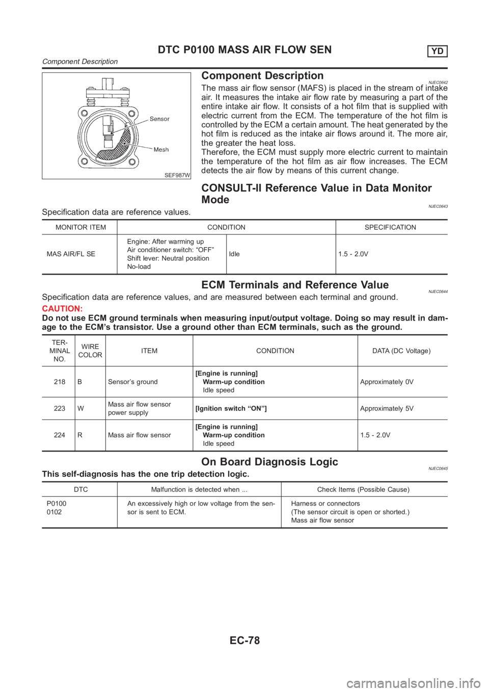
Component DescriptionNJEC0642The mass air flow sensor (MAFS) is placed in the stream of intake
air. It measures the intake air flow rate by measuring a part of the
entire intake air flow. It consists of a hot film that is supplied with
electric current from the ECM. The temperature of the hot film is
controlled by the ECM a certain amount. The heat generated by the
hot film is reduced as the intake air flows around it. The more air,
the greater the heat loss.
Therefore, the ECM must supply more electric current to maintain
the temperature of the hot film as air flow increases. The ECM
detects the air flow by means of this current change.
CONSULT-II Reference Value in Data Monitor
Mode
NJEC0643Specification data are reference values.
MONITOR ITEM CONDITION SPECIFICATION
MAS AIR/FL SEEngine: After warming up
Air conditioner switch: “OFF”
Shift lever: Neutral position
No-loadIdle 1.5 - 2.0V
ECM Terminals and Reference ValueNJEC0644Specification data are reference values, and are measured between each terminal and ground.
CAUTION:
Do not use ECM ground terminals when measuring input/output voltage. Doing so may result in dam-
age to the ECM’s transistor. Use a ground other than ECM terminals, such as the ground.
TER-
MINAL
NO.WIRE
COLORITEM CONDITION DATA (DC Voltage)
218 B Sensor’s ground[Engine is running]
Warm-up condition
Idle speedApproximately 0V
223 WMass air flow sensor
power supply[Ignition switch “ON”]Approximately 5V
224 R Mass air flow sensor[Engine is running]
Warm-up condition
Idle speed1.5 - 2.0V
On Board Diagnosis LogicNJEC0645This self-diagnosis has the one trip detection logic.
DTC Malfunction is detected when ... Check Items (Possible Cause)
P0100
0102An excessively high or low voltage from the sen-
sor is sent to ECM.Harness or connectors
(The sensor circuit is open or shorted.)
Mass air flow sensor
DTC P0100 MASS AIR FLOW SENYD
Component Description
EC-78
Page 3176 of 3189
A
A/C air flow (manual A/C) ..............................HA-19
A/C air flow <0011001100110011001100110011001100110011001100110011001100110011001100110011001100110011001100110011001100110011001100110011001100110011001100110011001100110011001100110011001100110011001100110011001100
110024>�TC-27
A/C component layout (manual A/C) .............HA-17
A/C compressor clutch removal and
installation (manual A/C).............................HA-82
A/C compressor clutch removal and
installation ...............................................ATC-139
A/C compressor precaution (manual
A/C) <0011001100110011001100110011001100110011001100110011001100110011001100110011001100110011001100110011001100110011001100110011001100110011001100110011001100110011001100110011001100110011001100110011001100
1100110011001100110011001100110011[....HA-5
A/C compressor precaution ............................ATC-7
A/C compressor special service tool
(manual A/C) .................................................HA-9
A/C compressor special service tool ............ATC-11
A/C control linkage adjustment (manual
A/C) <0011001100110011001100110011001100110011001100110011001100110011001100110011001100110011001100110011001100110011001100110011001100110011001100110011001100110011001100110011001100110011001100110011001100
1100110011001100110011001100110011[..HA-42
A/C control operation (manual A/C) ...............HA-18
A/C diagnostic work flow (manual A/C)..........HA-34
A/C evaporator (manual A/C) .........................HA-87
A/C HFC134a (R134a) system precau-
tion (manual A/C) ..........................................HA-2
A/C HFC134a (R134a) system
precaution <0011001100110011001100110011001100110011001100110011001100110011001100110011001100110011001100110011001100110011001100110011001100110011001100110011001100110011001100110011001100110011001100110011001100
110024>�TC-4
A/C HFC134a (R134a) system service
procedure (manual A/C) .............................HA-77
A/C HFC134a (R134a) system service
procedure ................................................ATC-133
A/C HFC134a (R134a) system service
tools (manual A/C) ......................................HA-10
A/C HFC134a (R134a) system service
tools<0011001100110011001100110011001100110011001100110011001100110011001100110011001100110011001100110011001100110011001100110011001100110011001100110011001100110011001100110011001100110011001100110011001100
110011001100110011001100110011[.ATC-11
A/C HFC134a system service equip-
ment precaution (manual A/C)......................HA-6
A/C HFC134a system service equip-
ment precaution ..........................................ATC-7
A/C lubricant (R134a) (manual A/C) ..............HA-79
A/C lubricant (R134a) ...................................ATC-20
A/C lubrication oil .......................................ATC-150
A/C operational check (manual A/C)..............HA-35
A/C operational check ..................................ATC-51
A/C performance chart (manual A/C).............HA-69
A/C performance test diagnoses
(manual A/C) ...............................................HA-67
A/C performance test diagnoses ..................ATC-89
A/C relay (manual A/C) ..................................HA-65
A/C reray <0011001100110011001100110011001100110011001100110011001100110011001100110011001100110011001100110011001100110011001100110011001100110011001100110011001100110011001100110011001100110011001100110011001100
110011001100110024[TC-85
A/C self-diagnoses (auto A/C) ......................ATC-42
A/C service data specification (manual
A/C) <0011001100110011001100110011001100110011001100110011001100110011001100110011001100110011001100110011001100110011001100110011001100110011001100110011001100110011001100110011001100110011001100110011001100
1100110011001100110011001100110011[..HA-96
A/C service data specification ....................ATC-150
A/C switch (manual A/C) ................................HA-65
A/C system description (auto A/C) ...............ATC-22
A/C trouble diagnoses (auto A/C) ................ATC-29
A/C, A - Wiring diagram................................ATC-33
A/C, M - Wiring diagram (manual A/C) ..........HA-25
A/CCUT - Wiring diagram (YD engine) ........EC-212
A/T - Wiring diagram - AT - FTS ...................AT-120
A/T - Wiring diagram - AT - MAIN .................AT-341A/T - Wiring diagram - AT - PNP/SW ............AT-114
A/T - Wiring diagram - AT -
VSS A/T........................................AT-127, AT-346
A/T fluid checking ............................................AT-13
A/T fluid replacement ......................................AT-13
A/T fluid temperature sensor.........................AT-123
A/T shift lock system - Wiring diagram .........AT-400
A/T shift lock system .....................................AT-399
A/T trouble diagnoses ........................AT-56, AT-256
A/T Wiring diagram - AT -
ENG SS........................................AT-131, AT-386
A/T Wiring diagram AT - 1ST ........................AT-137
A/T Wiring diagram AT - 2ND .......................AT-143
A/T Wiring diagram AT - 3RD .......................AT-149
A/T Wiring diagram AT - 4TH ........................AT-155
A/T Wiring diagram AT - BA/FTS.....AT-198, AT-380
A/T Wiring diagram AT - LPSV ........AT-167, AT-391
A/T Wiring diagram AT - OVRCSV ..AT-190, AT-370
A/T Wiring diagram AT - SSV/A.......AT-174, AT-360
A/T Wiring diagram AT - SSV/B.......AT-179, AT-365
A/T Wiring diagram AT - TCV ..........AT-162, AT-375
A/T Wiring diagram AT - TPS ..........AT-185, AT-355
A/T Wiring diagrawm AT -
VSSMTR ......................................AT-204, AT-351
ABS (anti-lock brake system).........................BR-45
ABS - Wiring diagram ....................................BR-50
ABS sensor rotor ............................................AX-24
Accelerator control system .........................FE-3, 14
Accelerator pedal position (APP) sen-
sor (QG engine) ..........EC-212, EC-219, EC-346,
EC-538, EC-545, EC-619
Accelerator pedal released position
learning (QG engine)....................EC-31, EC-426
Accelerator position sensor
(YD engine).................................................EC-89
Air bag disposal..............................................RS-35
Air bag precautions ...........................................GI-3
Air bag <0011001100110011001100110011001100110011001100110011001100110011001100110011001100110011001100110011001100110011001100110011001100110011001100110011001100110011001100110011001100110011001100110011001100
11001100110011001100110011[...RS-20
Air bleeding (hydraulic clutch) ........................CL-10
Air bleeding for brake system ..........................BR-8
Air cleaner and air duct (QG engine) ............EM-14
Air cleaner filter (QG engine).........................EM-14
Air conditioner cut control
(QG engine)..................................EC-26, EC-421
Air conditioner cut control (YD engine) ..........EC-19
Air flow meter - See Mass air flow sen-
sor (QG engine) .........................EC-135, EC-497
Air flow meter - See Mass air flow sen-
sor (YD engine) ..........................................EC-78
Air mix door control linkage adjustment
(manual A/C) ...............................................HA-44
Air mix door control linkage
adjustment ................................ATC-65, ATC-127
Air mix. door motor.......................ATC-63, ATC-127
Air spoiler, rear................................................BT-47
Alternator <0011001100110011001100110011001100110011001100110011001100110011001100110011001100110011001100110011001100110011001100110011001100110011001100110011001100110011001100110011001100110011001100110011001100
1100110011[...SC-30
Ambient sensor...........ATC-101, ATC-103, ATC-116
Angular tightening application
(QG engine)..................................................EM-3
Angular tightening application
(YD engine) ..................................................EM-3
ALPHABETICAL INDEX
IDX-2
Page 3181 of 3189
Lubricants<0011001100110011001100110011001100110011001100110011001100110011001100110011001100110011001100110011001100110011001100110011001100110011001100110011001100110011001100110011001100110011001100110011001100
1100110011[..MA-19
Lubrication circuit (engine) .........................LC-4, 26
Lubrication oil A/C ......................................ATC-150
M
M/T major overhaul ............................MT-30, 54, 92
M/T oil replacement..................................MT-14, 15
M/T removal and installation ..........................MT-23
MAFS - Wiring diagram
(QG engine)................................EC-137, EC-499
MAFS - Wiring diagram (YD engine) .............EC-80
Magnet clutch (manual A/C)...........................HA-82
Magnet clutch ...............................ATC-75, ATC-139
MAIN - Wiring diagram
(QG engine) ................................EC-111, EC-488
MAIN - Wiring diagram (YD engine) ..............EC-72
Mainshaft (M/T)..........................MT-39, 69, 93, 103
Malfunction indicator (MI)
(QG engine) .....EC-49, EC-398, EC-433, EC-717
Malfunction indicator lamp (MIL)
(YD engine).................................................EC-35
Manual air conditioner - Wiring diagram
(manual A/C) ...............................................HA-25
Manual transaxle number ................................GI-43
Mass air flow sensor (MAFS)
(QG engine)................................EC-135, EC-497
Mass air flow sensor (MAFS)
(YD engine).................................................EC-78
Master cylinder (brake) ..................................BR-14
Master cylinder (clutch) ...................................CL-11
Meter <0011001100110011001100110011001100110011001100110011001100110011001100110011001100110011001100110011001100110011001100110011001100110011001100110011001100110011001100110011001100110011001100110011001100
110011001100110011001100110011[...EL-110
MIL/DL - Wiring diagram
(QG engine) ...EC-398, EC-399, EC-717, EC-718
MIL/DL - Wiring diagram (YD engine)..........EC-213
MIRROR - Wiring diagram............................EL-251
Mirror defogger .............................................EL-173
Mirror, door<0011001100110011001100110011001100110011001100110011001100110011001100110011001100110011001100110011001100110011001100110011001100110011001100110011001100110011001100110011001100110011001100110011001100
110011[..BT-72
Misfire (QG engine) ......................................EC-226
Mode door control linkage adjustment
(manual A/C) ...............................................HA-42
Mode door control linkage
adjustment ................................ATC-62, ATC-126
Mode door motor ..........................ATC-59, ATC-126
Model variation ................................................GI-39
Molding - See Exterior ....................................BT-47
Multi-remote control system..........................EL-352
Multiport fuel injection (MFI) system
(QG engine)..................................EC-23, EC-418
Multiport fuel injection precautions ....................GI-6
N
NATS (Nissan anti-theft system)
precautions <0011001100110011001100110011001100110011001100110011001100110011001100110011001100110011001100110011001100110011001100110011001100110011001100110011001100110011001100110011001100110011001100110011001100
110011[GI-3
NATS (Nissan anti-theft system)...................EL-386
NATS - Wiring diagram .................................EL-388
NVH troubleshooting (AX) ................................AX-3NVH troubleshooting (BR)................................BR-6
NVH troubleshooting (CL) ................................CL-4
NVH troubleshooting (EM) (QG engine)..........EM-9
NVH troubleshooting (M/T) ............................MT-13
NVH troubleshooting (ST).................................ST-5
NVH troubleshooting (SU)..............................SU-16
NVIS (Nissan vehicle immobilizer sys-
tem) precautions ............................................GI-3
O
Oil pan (engine) (QG engine) ........................EM-22
Oil pan (YD engine) .......................................EM-15
Oil pressure (engine) ..................................LC-5, 27
Oil pump (engine) .......................................LC-5, 27
Oil pump regulator valve (engine) ..............LC-7, 29
On board diagnostic system
(QG engine)..................................EC-36, EC-430
On board diagnostic system
(YD engine).................................................EC-34
Operating cylinder (clutch)..............................CL-14
Overdrive control switch ..................AT-243, AT-339
Overheat (QG engine) ...................EC-325, EC-598
Oversize piston (QG engine) .........................EM-88
P
Park/neutral position switch (A/T) .................AT-112
Park/neutral position switch (M/T)..................MT-21
Park/Neutral position switch
(QG engine)................................EC-357, EC-691
Park/Neutral position switch
(YD engine)...............................................EC-208
Parking brake control .....................................BR-43
Parking lamp <0011001100110011001100110011001100110011001100110011001100110011001100110011001100110011001100110011001100110011001100110011001100110011001100110011001100110011001100110011001100110011001100110011001100
110028[L-55
PCV (positive crankcase ventilation)
(QG engine)................................EC-403, EC-722
PCV (positive crankcase ventilation)
(YD engine).................................................EC-19
PGC/V - Wiring diagram (QG engine) .........EC-254
PHASE - Wiring diagram
(QG engine)................................EC-242, EC-565
Piston assembly (QG engine)........................EM-88
Piston assembly (YD engine) ........................EM-81
Piston pin inspection (QG engine).................EM-84
Piston pin inspection (YD engine) .................EM-71
Piston ring inspection (QG engine) ...............EM-85
Piston ring inspection (YD engine) ................EM-71
Piston to bore clearance
(QG engine) ...................................EM-88, EM-89
Piston to bore clearance (YD engine) ...........EM-73
PNP/SW - Wiring diagram (QG engine) ......EC-359
PNP/SW - Wiring diagram (YD engine) .......EC-208
PNPSW1 - Wiring diagram
(QG engine) ..............................................EC-692
POS - Wiring diagram
(QG engine)................................EC-236, EC-558
POWER - Wiring diagram...............................EL-14
GI
MA
EM
LC
EC
FE
CL
MT
AT
AX
SU
BR
ST
RS
BT
HA
SC
EL
ALPHABETICAL INDEX
IDX-7