2003 NISSAN ALMERA N16 adding oil
[x] Cancel search: adding oilPage 2191 of 3189
SBR451D
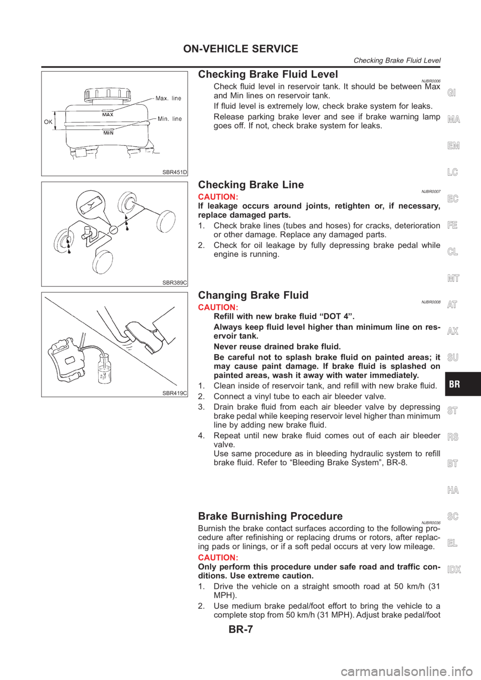
Checking Brake Fluid LevelNJBR0006Check fluid level in reservoir tank. It should be between Max
and Min lines on reservoir tank.
If fluid level is extremely low, check brake system for leaks.
Release parking brake lever and see if brake warning lamp
goes off. If not, check brake system for leaks.
SBR389C
Checking Brake LineNJBR0007CAUTION:
If leakage occurs around joints, retighten or, if necessary,
replace damaged parts.
1. Check brake lines (tubes and hoses) for cracks, deterioration
or other damage. Replace any damaged parts.
2. Check for oil leakage by fully depressing brake pedal while
engine is running.
SBR419C
Changing Brake FluidNJBR0008CAUTION:
Refill with new brake fluid “DOT 4”.
Always keep fluid level higher than minimum line on res-
ervoir tank.
Never reuse drained brake fluid.
Be careful not to splash brake fluid on painted areas; it
may cause paint damage. If brake fluid is splashed on
painted areas, wash it away with water immediately.
1. Clean inside of reservoir tank, and refill with new brake fluid.
2. Connect a vinyl tube to each air bleeder valve.
3. Drain brake fluid from each air bleeder valve by depressing
brake pedal while keeping reservoir level higher than minimum
line by adding new brake fluid.
4. Repeat until new brake fluid comes out of each air bleeder
valve.
Use same procedure as in bleeding hydraulic system to refill
brake fluid. Refer to “Bleeding Brake System”, BR-8.
Brake Burnishing ProcedureNJBR0036Burnish the brake contact surfaces according to the following pro-
cedure after refinishing or replacing drums or rotors, after replac-
ing pads or linings, or if a soft pedal occurs at very low mileage.
CAUTION:
Only perform this procedure under safe road and traffic con-
ditions. Use extreme caution.
1. Drive the vehicle on a straight smooth road at 50 km/h (31
MPH).
2. Use medium brake pedal/foot effort to bring the vehicle to a
complete stop from 50 km/h (31 MPH). Adjust brake pedal/foot
GI
MA
EM
LC
EC
FE
CL
MT
AT
AX
SU
ST
RS
BT
HA
SC
EL
IDX
ON-VEHICLE SERVICE
Checking Brake Fluid Level
BR-7
Page 2261 of 3189
Service NoticeNJBT0001When removing or installing various parts, place a cloth or padding onto the vehicle body to prevent
scratches.
Handle trim, molding, instruments, grille, etc. carefully during removing or installing. Be careful not to oil
or damage them.
Apply sealing compound where necessary when installing parts.
When applying sealing compound, be careful that the sealing compound doesnot protrude from parts.
When replacing any metal parts (for example body outer panel, members, etc.),besuretotakerustpre-
vention measures.
Supplemental Restraint System (SRS) “AIR
BAG” and “SEAT BELT PRE-TENSIONER”
NJBT0002The Supplemental Restraint System such as “AIR BAG” and “SEAT BELT PRE-TENSIONER” used along with
a seat belt, helps to reduce the risk or severity of injury to the driver and front passenger for certain types of
collision. The SRS system composition which is available to NISSAN MODEL N16 is as follows (The compo-
sition varies according to the destination and optional equipment.):
For a frontal collision
The Supplemental Restraint System consists of driver air bag module (located in the center of the steer-
ing wheel), front passenger air bag module (located on the instrument panel on passenger side), front seat
belt pre-tensioners, a diagnosis sensor unit, warning lamp, wiring harness and spiral cable.
For a side collision
The Supplemental Restraint System consists of front side air bag module (located in the outer side of front
seat), side air bag (satellite) sensor, diagnosis sensor unit (one of components of air bags for a frontal
collision), wiring harness, warning lamp (one of components of air bags for a frontal collision).
Information necessary to service the system safely is included in theRS sectionof this Service Manual.
WARNING:
To avoid rendering the SRS inoperative, which could increase the risk of personal injury or death
in the event of a collision which would result in air bag inflation, all maintenance should be per-
formed by an authorized NISSAN dealer.
Improper maintenance, including incorrect removal and installation of the SRS, can lead to per-
sonal injury caused by unintentional activation of the system. For removalofSpiralCableandAir
Bag Module, see the RS section.
Do not use electrical test equipment on any circuit related to the SRS unless instructed to in this
Service Manual. SRS wiring harnesses can be identified by yellow or/and orange harness connec-
tor.
GI
MA
EM
LC
EC
FE
CL
MT
AT
AX
SU
BR
ST
RS
HA
SC
EL
IDX
PRECAUTIONS
Service Notice
BT-3
Page 2265 of 3189
Removal and InstallationNJBT0004When removing or installing hood, place a cloth or other padding on hood. This prevents vehicle body from
being scratched.
Bumper fascia is made of plastic. Do not use excessive force and be sure to keep oil away from it.
Hood adjustment: Adjust at hinge portion.
Hood lock adjustment: After adjusting, check hood lock control operation. Apply a coat of grease to hood
locks engaging mechanism.
Hood opener: Do not attempt to bend cable forcibly. Doing so increases effort required to unlock hood.
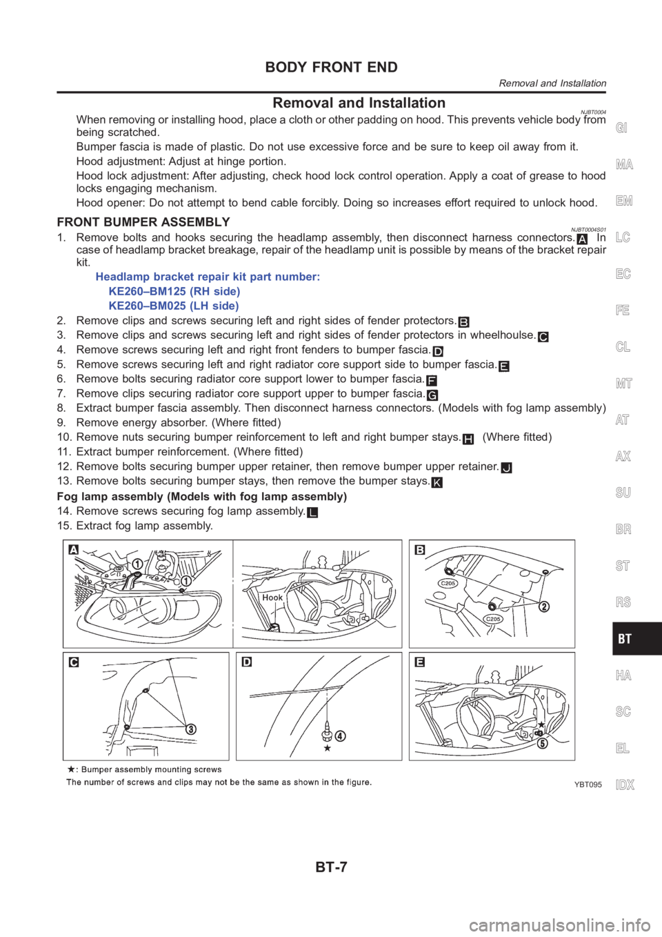
FRONT BUMPER ASSEMBLYNJBT0004S011. Remove bolts and hooks securing the headlamp assembly, then disconnectharness connectors.In
case of headlamp bracket breakage, repair of the headlamp unit is possibleby means of the bracket repair
kit.
Headlamp bracket repair kit part number:
KE260–BM125 (RH side)
KE260–BM025 (LH side)
2. Remove clips and screws securing left and right sides of fender protectors.
3. Remove clips and screws securing left and right sides of fender protectors in wheelhoulse.
4. Remove screws securing left and right front fenders to bumper fascia.
5. Remove screws securing left and right radiator core support side to bumper fascia.
6. Remove bolts securing radiator core support lower to bumper fascia.
7. Remove clips securing radiator core support upper to bumper fascia.
8. Extract bumper fascia assembly. Then disconnect harness connectors. (Models with fog lamp assembly)
9. Remove energy absorber. (Where fitted)
10. Remove nuts securing bumper reinforcement to left and right bumper stays.
(Where fitted)
11. Extract bumper reinforcement. (Where fitted)
12. Remove bolts securing bumper upper retainer, then remove bumper upperretainer.
13. Remove bolts securing bumper stays, then remove the bumper stays.
Fog lamp assembly (Models with fog lamp assembly)
14. Remove screws securing fog lamp assembly.
15. Extract fog lamp assembly.
YBT095
GI
MA
EM
LC
EC
FE
CL
MT
AT
AX
SU
BR
ST
RS
HA
SC
EL
IDX
BODY FRONT END
Removal and Installation
BT-7
Page 2268 of 3189
Removal and Installation (Sedan)NJBT0005When removing or installing trunk lid, place a cloth or other padding on trunk lid. This prevents vehicle
body from being scratched.
Bumper fascia is made of plastic. Do not use excessive force and be sure to keep oil away from it.
Trunk lid adjustment: Adjust at hinge-trunk lid portion for proper trunk lid fit.
Trunk lid lock system adjustment: Adjust striker so that it is in the centerof the lock. After adjustment, check
trunk lid lock operation.
After installation, make sure that trunk lid and fuel filler lid open smoothly.
REAR BUMPER ASSEMBLYNJBT0005S011. Remove clips and screws securing left and right chipping protectors.
2. Remove screws securing left and right rear fenders to bumper fascia.
3. Remove bolts securing bumper fascia assembly.
4. Remove clips securing bumper fascia assembly.
5. Open the bumper fascia side outward to disengage from side clips.
6. Extract bumper fascia assembly.
7. Remove bolts securing bumper stays, then remove the bumper stays.
BODY REAR END AND OPENER
Removal and Installation (Sedan)
BT-10
Page 2271 of 3189
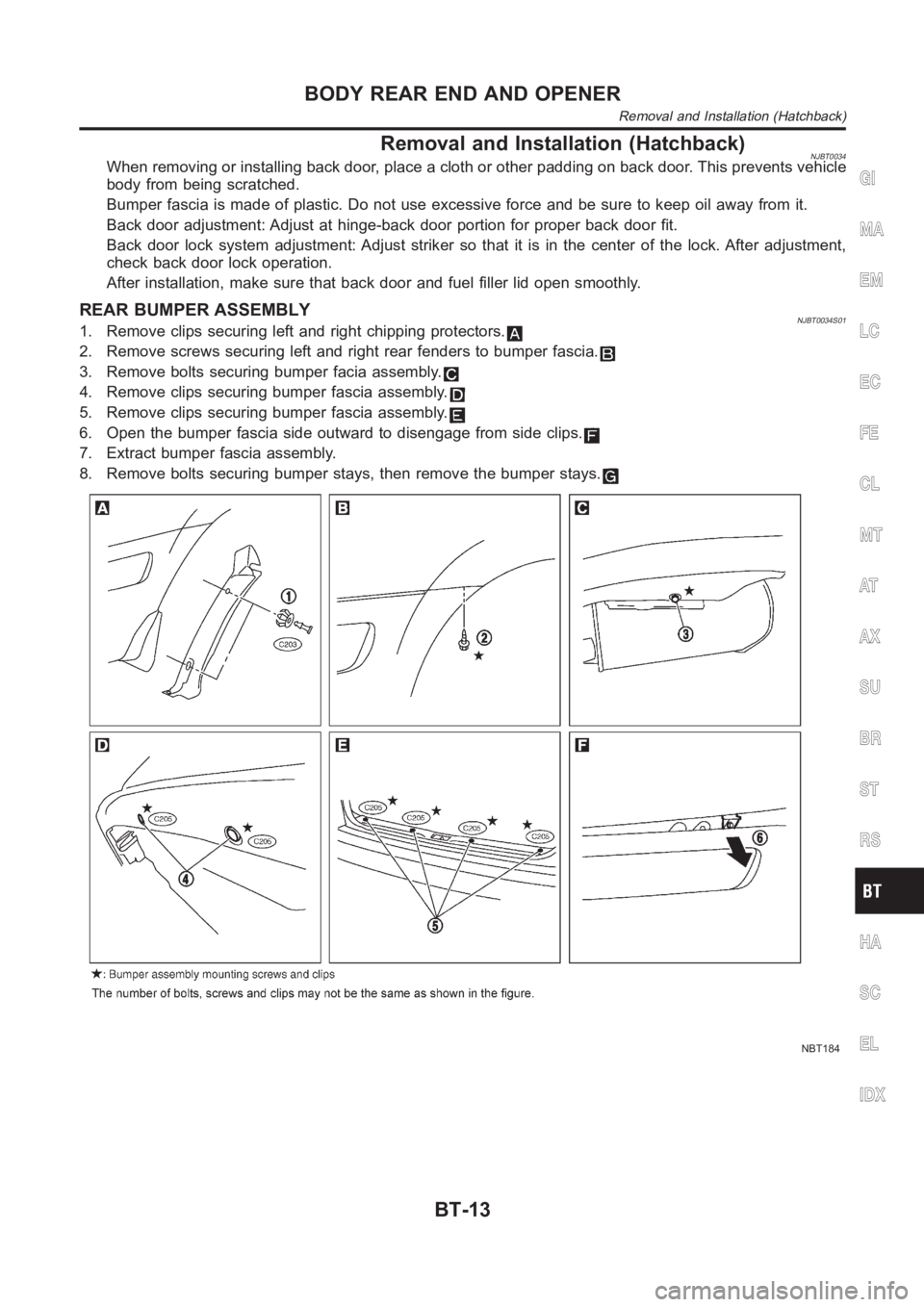
Removal and Installation (Hatchback)NJBT0034When removing or installing back door, place a cloth or other padding on back door. This prevents vehicle
body from being scratched.
Bumper fascia is made of plastic. Do not use excessive force and be sure to keep oil away from it.
Back door adjustment: Adjust at hinge-back door portion for proper back door fit.
Back door lock system adjustment: Adjust striker so that it is in the centerof the lock. After adjustment,
check back door lock operation.
After installation, make sure that back door and fuel filler lid open smoothly.
REAR BUMPER ASSEMBLYNJBT0034S011. Remove clips securing left and right chipping protectors.
2. Remove screws securing left and right rear fenders to bumper fascia.
3. Remove bolts securing bumper facia assembly.
4. Remove clips securing bumper fascia assembly.
5. Remove clips securing bumper fascia assembly.
6. Open the bumper fascia side outward to disengage from side clips.
7. Extract bumper fascia assembly.
8. Remove bolts securing bumper stays, then remove the bumper stays.
NBT184
GI
MA
EM
LC
EC
FE
CL
MT
AT
AX
SU
BR
ST
RS
HA
SC
EL
IDX
BODY REAR END AND OPENER
Removal and Installation (Hatchback)
BT-13