Page 731 of 3189
![NISSAN ALMERA N16 2003 Electronic Repair Manual EVAPORATIVE EMISSION SYSTEM
EC-401
[QG (WITH EURO-OBD)]
C
D
E
F
G
H
I
J
K
L
MA
EC
Component InspectionEBS00KDK
EVAP CANISTER
Check EVAP canister as follows:
1. Block port B . Orally blow air through p NISSAN ALMERA N16 2003 Electronic Repair Manual EVAPORATIVE EMISSION SYSTEM
EC-401
[QG (WITH EURO-OBD)]
C
D
E
F
G
H
I
J
K
L
MA
EC
Component InspectionEBS00KDK
EVAP CANISTER
Check EVAP canister as follows:
1. Block port B . Orally blow air through p](/manual-img/5/57350/w960_57350-730.png)
EVAPORATIVE EMISSION SYSTEM
EC-401
[QG (WITH EURO-OBD)]
C
D
E
F
G
H
I
J
K
L
MA
EC
Component InspectionEBS00KDK
EVAP CANISTER
Check EVAP canister as follows:
1. Block port B . Orally blow air through port A .
Check that air flows freely through port C .
2. Block port A . Orally blow air through port B .
Check that air flows freely through port C .
FUEL CHECK VALVE
1. Blow air through connector on fuel tank side.
A considerable resistance should be felt and a portion of air flow
should be directed toward the EVAP canister side.
2. Blow air through connector on EVAP canister side.
Air flow should be smoothly directed toward fuel tank side.
3. If fuel check valve is suspected of not properly functioning in
steps 1 and 2 above, replace it.
FUEL TANK VACUUM RELIEF VALVE (BUILT INTO FUEL FILLER CAP)
1. Wipe clean valve housing.
2. Check valve opening pressure and vacuum.
3. If out of specification, replace fuel filler cap as an assembly.
EVAP CANISTER PURGE VOLUME CONTROL SOLENOID VALVE
Refer to EC-256, "Component Inspection" .
PBIB0663E
SEF552Y
SEF989X
Pres-
sure:15.3 - 20.0 kPa (0.153 - 0.200 bar,
0.156 - 0.204 kg/cm
2 , 2.22 - 2.90 psi)
Va c u u m :−6.0 to −3.3 kPa (−0.060 to −0.033 bar,
−0.061 to −0.034 kg/cm
2 , −0.87 to −0.48 psi)
SEF943S
Page 1049 of 3189
![NISSAN ALMERA N16 2003 Electronic Repair Manual EVAPORATIVE EMISSION SYSTEM
EC-719
[QG (WITHOUT EURO-OBD)]
C
D
E
F
G
H
I
J
K
L
MA
EC
Component InspectionEBS00KMI
EVAP CANISTER
Check EVAP canister as follows:
1. Block port B . Orally blow air throug NISSAN ALMERA N16 2003 Electronic Repair Manual EVAPORATIVE EMISSION SYSTEM
EC-719
[QG (WITHOUT EURO-OBD)]
C
D
E
F
G
H
I
J
K
L
MA
EC
Component InspectionEBS00KMI
EVAP CANISTER
Check EVAP canister as follows:
1. Block port B . Orally blow air throug](/manual-img/5/57350/w960_57350-1048.png)
EVAPORATIVE EMISSION SYSTEM
EC-719
[QG (WITHOUT EURO-OBD)]
C
D
E
F
G
H
I
J
K
L
MA
EC
Component InspectionEBS00KMI
EVAP CANISTER
Check EVAP canister as follows:
1. Block port B . Orally blow air through port A .
Check that air flows freely through port C .
2. Block port A . Orally blow air through port B .
Check that air flows freely through port C .
FUEL CHECK VALVE
1. Blow air through connector on fuel tank side.
A considerable resistance should be felt and a portion of air flow
should be directed toward the EVAP canister side.
2. Blow air through connector on EVAP canister side.
Air flow should be smoothly directed toward fuel tank side.
3. If fuel check valve is suspected of not properly functioning in
steps 1 and 2 above, replace it.
FUEL TANK VACUUM RELIEF VALVE (BUILT INTO FUEL FILLER CAP)
1. Wipe clean valve housing.
2. Check valve opening pressure and vacuum.
3. If out of specification, replace fuel filler cap as an assembly.
EVAP CANISTER PURGE VOLUME CONTROL SOLENOID VALVE
Refer to EC-676, "Component Inspection" .
PBIB0663E
SEF552Y
SEF989X
Pres-
sure:15.3 - 20.0 kPa (0.153 - 0.200 bar,
0.156 - 0.204 kg/cm
2 , 2.22 - 2.90 psi)
Va c u u m :−6.0 to −3.3 kPa (−0.060 to −0.033 bar,
−0.061 to −0.034 kg/cm
2 , −0.87 to −0.48 psi)
SEF943S
Page 1082 of 3189

JEF360Y
JEF361Y
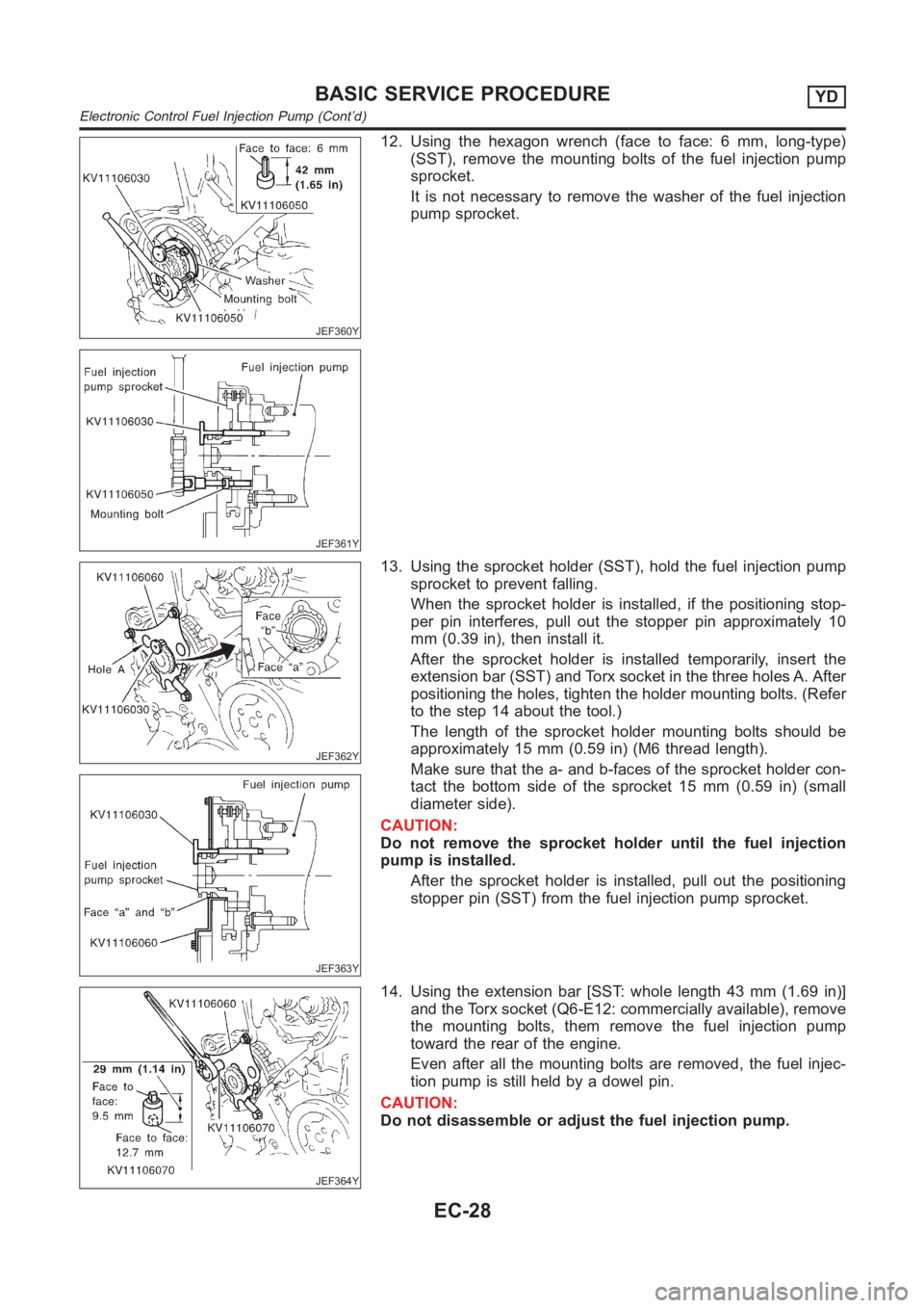
12. Using the hexagon wrench (face to face: 6 mm, long-type)
(SST), remove the mounting bolts of the fuel injection pump
sprocket.
It is not necessary to remove the washer of the fuel injection
pump sprocket.
JEF362Y
JEF363Y
13. Using the sprocket holder (SST), hold the fuel injection pump
sprocket to prevent falling.
When the sprocket holder is installed, if the positioning stop-
per pin interferes, pull out the stopper pin approximately 10
mm (0.39 in), then install it.
After the sprocket holder is installed temporarily, insert the
extension bar (SST) and Torx socket in the three holes A. After
positioning the holes, tighten the holder mounting bolts. (Refer
to the step 14 about the tool.)
The length of the sprocket holder mounting bolts should be
approximately 15 mm (0.59 in) (M6 thread length).
Make sure that the a- and b-faces of the sprocket holder con-
tact the bottom side of the sprocket 15 mm (0.59 in) (small
diameter side).
CAUTION:
Do not remove the sprocket holder until the fuel injection
pump is installed.
After the sprocket holder is installed, pull out the positioning
stopper pin (SST) from the fuel injection pump sprocket.
JEF364Y
14. Using the extension bar [SST: whole length 43 mm (1.69 in)]
and the Torx socket (Q6-E12: commercially available), remove
the mounting bolts, them remove the fuel injection pump
toward the rear of the engine.
Even after all the mounting bolts are removed, the fuel injec-
tion pump is still held by a dowel pin.
CAUTION:
Do not disassemble or adjust the fuel injection pump.
BASIC SERVICE PROCEDUREYD
Electronic Control Fuel Injection Pump (Cont’d)
EC-28
Page 2170 of 3189

SFA449BB
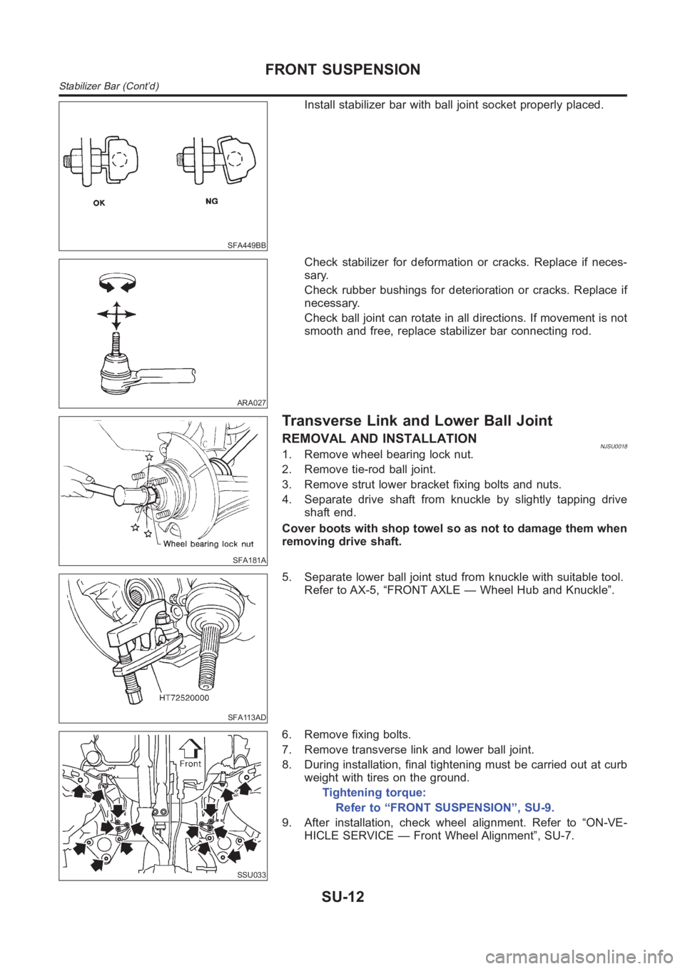
Install stabilizer bar with ball joint socket properly placed.
ARA027
Check stabilizer for deformation or cracks. Replace if neces-
sary.
Check rubber bushings for deterioration or cracks. Replace if
necessary.
Check ball joint can rotate in all directions. If movement is not
smooth and free, replace stabilizer bar connecting rod.
SFA181A
Transverse Link and Lower Ball Joint
REMOVAL AND INSTALLATIONNJSU00181. Remove wheel bearing lock nut.
2. Remove tie-rod ball joint.
3. Remove strut lower bracket fixing bolts and nuts.
4. Separate drive shaft from knuckle by slightly tapping drive
shaft end.
Cover boots with shop towel so as not to damage them when
removing drive shaft.
SFA113AD
5. Separate lower ball joint stud from knuckle with suitable tool.
Refer to AX-5, “FRONT AXLE — Wheel Hub and Knuckle”.
SSU033
6. Remove fixing bolts.
7. Remove transverse link and lower ball joint.
8. During installation, final tightening must be carried out at curb
weight with tires on the ground.
Tightening torque:
Refer to “FRONT SUSPENSION”, SU-9.
9. After installation, check wheel alignment. Refer to “ON-VE-
HICLE SERVICE — Front Wheel Alignment”, SU-7.
FRONT SUSPENSION
Stabilizer Bar (Cont’d)
SU-12